RAB Lighting EZPAN2X4-30N/D10/LC Operating instructions
- Type
- Operating instructions

EZPAN EDGELIT PANEL FAMILY
INSTALLATION INSTRUCTIONS
Call the Marketing Department at 888-
722
-1000 or email: marketing@rablighting.com
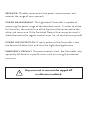
SAFETY INSTRUCTIONS
WARNING: Suitable for 9/16” or 15/16” Flat Tee Grid in both Insulated Ceilings and Non-Insulated Ceilings. Access above
ceiling required.
WARNING: Vapor barrier must be suitable for 90° C.
WARNING: Fixture to be independently supported to building structure.
IMPORTANT
READ CAREFULLY BEFORE INSTALLING FIXTURE. RETAIN THESE INSTRUCTIONS FOR FUTURE REFERENCE.
is required for safety. THIS PRODUCT MUST BE INSTALLED IN ACCORDANCE WITH THE APPLICABLE INSTALLATION CODE BY A
PERSON FAMILIAR WITH THE CONSTRUCTION AND OPERATION OF THE PRODUCT AND THE HAZARDS INVOLVED.
EZPAN 1X4
EZPAN 2X2
EZPAN 2X4
CLEANING & MAINTENANCE
1. Clean polystyrene lens
cleaning solution.
2.
LEDs.
TROUBLESHOOTING
1.
wiring directions.
2.
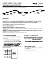
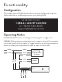
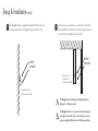
Universal voltage driver permits operation at 120V thru 277V,
50 or 60 Hz. For 0-10V Dimming, follow the wiring directions
as shown (Fig. 1).
1.
2.
lead.
3.
4.
5.
NOTE: Do not connect DIM V+ (purple)/ DIM V- (gray) to line
voltage or supply ground.
Fig. 1
®

EZPAN EDGELIT PANEL FAMILY
INSTALLATION INSTRUCTIONS
Call the Marketing Department at 888 722- -1000 or email: marketing@rablighting.com
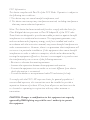
40
30
50
)W(noitceleS rewoP
4000
5000
)K(noitcele
S roloC
3500
30
25
40
)W(noitceleS rewoP
4000
5000
)K(noitceleS roloC
3500
2x2
1x4
2x4
Access Plate
Wattage Switch Selector Switches
CCT Switch
Conduit Knockouts
Silicone Cover
Fixture
Grid Clip
Tee-Grid
Bar
Access Plate Screw
Splice Box
Grid Clip
Hole
Grid
Clip
Power
Feed
Fixture
Firmly bend Grid
Clips up and out
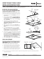
RECESSED CEILING MOUNTING
application. Above ceiling access required.
To mount in an insulated or non-insulated ceiling - 9/16” or
15/16” exposed Flat Tee Grid Ceiling follow the steps below.
1. Firmly bend the pre-installed Grid Clips (up and out as
shown in Fig. 2.
2. Rotate and slide the Fixture
the Tee-Grid Bar and place it as indicated by the
directional arrow as shown in Fig. 3. Secure the Fixture
to the Tee-Grid Bar.
3. Support wires are required by Installation Codes.
Support the Fixture to the building structure by
Support Wires (supplied by others) through the Grid
Clip Hole as shown in Fig. 4.
4. Make sure that the orientation of the Splice Box and
Access Plate faces an accessible tile to make electrical
splices.
5. Loosen Access Plate Screw and remove the Access
Plate. Knock out appropriate Conduit Knockouts on
the Access Plate to route input conduit. Use appropriate
conduit connectors as required by code (Fig. 5).
6. Connect wires as shown in wiring diagram. Push all wires
back into the Splice Box. Use appropriate UL approved
wire connectors as required by code to complete wiring.
Be careful not to pinch wires. WARNING: To prevent
wiring damage or abrasion, do not expose wiring to
edges of sheet metal or other sharp objects.
7. Replace Access Plate and tighten Access Plate Screw.
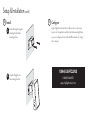
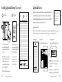
FIELD ADJUSTMENT
If the option is available, follow the following instructions to
factory settings.
Factory Settings: 4000K, 30W (1X4, 2X2), 40W (2X4)
1. Locate the selector switches on the side of the driver
2. Select a wattage and color temperature by sliding the
respective switch up or down to the desired value
3. After the switches are positioned to the desired settings,
insert the silicone cover to lock the switches in place
Support Wire
(supplied by others)
Fig. 3
Fig. 2
Fig. 4
Fig. 5
Easy Answers
rablighting.com
Visit our website for product info
Tech Help Line
Call our experts: 888 722-1000
e-mail
Answered promptly - sales@rablighting.com
Free Lighting Layouts
Answered online or by request
© 2019 RAB LIGHTING Inc.
Northvale, New Jersey 07647 USA
Note: These instructions do not cover all details or variations in equipment nor do they provide for every possible situation during installation,
operation or maintenance.
EZPAN EDGELIT PANEL FAMILY
1.6”
®

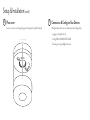
Welcome
LCSENSE15/D10
Ceiling Sensor
© RAB Lighting, Inc
170 Ludlow Avenue Northvale, NJ 07647
Custom manufactured in China
1 (844) LIGHTCLOUD
1 (844) 544-4825
Lightcloud is a commercial
wireless lighting control system
& service. It’s powerful and
flexible, yet easy to use
and install. Learn more at
lightcloud.com
1 (844) LIGHTCLOUD
1 (844) 544-4825
WE ’RE HERE TO HELP:

Lightcloud is a wireless
lighting control service.
The Lightcloud Ceiling
Sensor is a remotely
configurable passive infrared
motion sensor that can
switch and dim both hard-
wired circuits and remote
circuits using Lightcloud
Controllers.
Hello
Product Features
Advanced PIR Sensing
Secure Cloud Control & Configuration
Retrofit-Friendly Local Control
Scheduling & Astronomical Clock
Power Monitoring
0-10V Dimming
Patent Pending

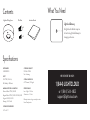
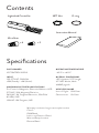
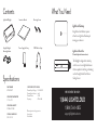
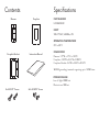
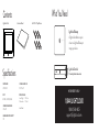
Contents
PART NUMBER
LCSENSE15/D10
INPUT
120-277VAC, 50/60Hz,
<1W (Standby) - 2W (Active)
MAXIMUM SWITCHED LOAD RATINGS
Electronic Ballast: 277VAC, 3300W
Magnetic Ballast: 277VAC, 1200W / 120VAC, 800W
Tungsten: 220VAC, 3000W
Dimming: 0-10V (Class2)
OPERATING TEMPERATURE
-20ºC to 40ºC
Specifications
OPERATING HUMIDITY
10% RH to 95% RH
Non-Condensing
OVERALL DIMENSIONS
4.91” Diameter, 1.61” Height
WIRELESS RANGE
Line-of-Sight: 1000 feet
Obstructions: 100 feet
Warranty is active as long as service plan is active.
Indoor Damp Location
Lightcloud Ceiling Sensor Instruction Manual
Wire Nuts
x 4
x 2
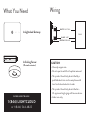
What You Need
Lightcloud Gateway
A Lightcloud installation requires
at least one Lightcloud Gateway to
manage your devices.
1 (844) LIGHTCLOUD
or 1 (844) 544-4825
WE’RE HERE TO HELP:

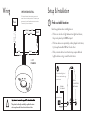
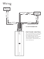
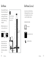
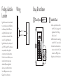
Wiring
SWITCHED NEUTRAL
The “Switched Neutral” white with red stripe wire is the
neutral line for the load being switched. This enables power
measurement. See the Power Measurement section under
“Functionality” for more information.
BLACK
WHITE/RED
0-10V
DIMMING
Panel
Load
BLACK / HOT
WHITE / NEUTRAL
WHITE
BLACK
RED
WHITE
PURPLE
GRAY
PURPLE
GRAY
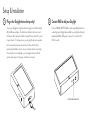
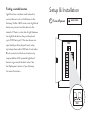
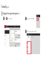
Setup & Installation
1
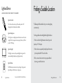
Find a suitable location
Use these guidelines when installing devices:
• If there is a clear line of sight between two Lightcloud devices,
they can be placed up to 1000 feet apart.
• If the two devices are separated by ordinary drywall construction,
try to keep them within 100 feet of each other.
• Brick, concrete and steel construction may require additional
Lightcloud devices to go around the obstruction.
!
This product should only be installed by a qualified electrician
and in compliance with local and national electrical codes.
Lightcloud Gateway
<= 100 ft.
Add an additional Lightcloud
Device to extend network range
around corners
BR I C K ,
CONC RE T E OR
ME TAL W A L L
DRY WA L L
OR S I MIL AR

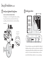
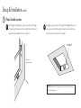
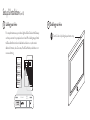
Setup & Installation (cont’d)
DE VIC E I Ds
3
Labeling your device
For setup and maintenance, we provide two Lightcloud Device Tables with
the Gateway: one that you can attach to your panel and one to hand o to
a building manager. Attach the Device Identification stickers included with
each device to a row, then write in additional information, such as Zone
name, Panel/Circuit Number, and whether or not a zone uses dimming.
ZO NE NA M E
PANEL /
CI RCUIT #
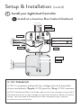
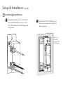
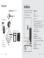
INSTALL AT A JUNCTION BOX INDOOR/OUTDOOR
The Ceiling Sensor can control other Lightcloud devices, wirelessly.
If you don’t need to hard-wire a switched circuit to the Sensor,
no problem—just tie the white/red wire to neutral and cap o any
unused wires.
2
Install your Lightcloud Ceiling Sensor
Sensor attached
attached to wired
junction box

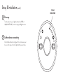
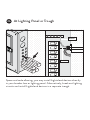
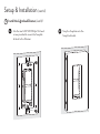
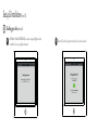
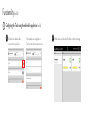
Setup & Installation (cont’d)
4
5
Power up
Confirm device connectivity
Confirm Status Indicator is solid green. If it is not, make sure your
device is within range of another Lightcloud AC-powered device.
To add new devices to your Lightcloud network, call RAB at
1 (844) LIGHTCLOUD, or email us at [email protected].
STATUS
INDICATOR

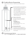
Setup & Installation (cont’d)
6
Place cover
Secure cover onto sensor by pushing up and twisting to the right (clockwise).
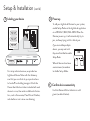
7
Commission & Configure Your Devices
All Lightcloud products can be commissioned and configured by:
• Logging on to lightcloud.com
• Calling RAB at 1 (844) LIGHTCLOUD
• Emailing us at [email protected]

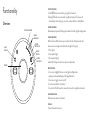
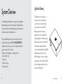
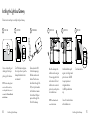
Functionality
Overview
STATUS INDICATOR
POWER
INDICATOR
DEVICE
BUTTON
MOTION
INDICATOR
LIGHT
SENSOR
SENSOR
SIGNAL
INDICATOR
STATUS INDICATOR:
• Solid GREEN when connected to your Lightcloud network
• Blinking RED when not connected to a Lightcloud network. The device will
automatically continue trying to connect to a network that is in Setup Mode.
POWER INDICATOR:
Illuminated when powered. Blinking when indicated from the Lightcloud application.
SIGNAL INDICATOR:
After the Device Button has been pressed, this indicator illuminates when the
device receives a message and indicates the strength of the signal.
3 - Best Signal
2 - Acceptable Signal
1 - Unacceptable Signal
Consult the “Finding a Location” section for more information.
DEVICE BUTTON:
• Press once to highlight this device in the Lightcloud Application
(pressing once also enables display of the Signal Indicators)
• Press twice to toggle circuit on and o
• Press twice and hold to set dim level
• Press and hold for 10 seconds to remove this device from a Lightcloud network
MOTION INDICATOR:
Illuminates when motion is detected
SENSOR:
Passive-infrared motion sensor

OCCUPANCY & VACANCY SENSING:
The Lightcloud Ceiling Sensor can operate in either Occupancy or Vacancy Sensor
modes, selectable via the Lightcloud application. In Occupancy mode, the attached
circuit will be switched on when motion is detected, and o (or dimmed) when the
timeout expires. In Vacancy mode, the attached circuit will be turned o when the
motion timeout expires, but will only be turned on via the Lightcloud application,
Lightcloud Wall Switch, or similar. Motion detection and timeout can still be used
via Lightcloud Automations to control other devices.
CONTROLLER MODE:
In Controller Mode, the attached circuit is controllable as an independent zone
in the Lightcloud application. Motion detection and timeout can still be used via
Lightcloud Automations to control other devices.
RANGE TEST MODE:
When Range Test Mode is activated via the Lightcloud application, the timeout
period is shortened so that you can test dierent sensitivities quickly. All indicators
will go o except for the Motion Indicator. When satisfied, turn o Range Test
Mode to continue normal operation.
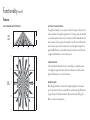
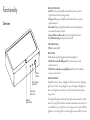
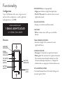
Functionality (cont’d)
Features
SIDE
VIEW
TOP
VIEW
15’ 7.5’ 7.5’ 15’
30’
9’
0’
0’
7.5’
7.5’
15’
15’
PASSIVE INFRARED MOTION DETECTION

POWER LOSS DETECTION:
If power to the Ceiling Sensor is lost, the device will detect this and alert the
Lightcloud application.
EMERGENCY DEFAULT:
If communication is lost, the Ceiling Sensor may optionally fall back to a specific
state, such as turning the attached circuit on. This may be configured via the
Lightcloud application or by calling RAB.
Functionality (cont’d)
Features
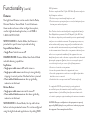
010V DIMMING:
0-10V is a common method of low-voltage control of dimmable drivers and ballasts.
Purple: 0-10V positive | Gray: 0-10V common
Note: The National Electrical Code requires that low-voltage wiring used in the same
enclosure as high voltage wiring have an equal or better insulation rating. You may need
to complete your low-voltage wiring in another enclosure or use a partition.
DEVICE IDENTIFICATION:
For help with installation, there are two ways to identify this device:
• Pressing the Device Button on the actual product will produce a message in
the Lightcloud application indicating which device you are working with.
• Pressing the “Indicate” button in the Lightcloud application will cause the
device’s Status Indicator to blink green. This will also switch the device’s relay
on and o repeatedly, allowing you to quickly identify which circuit it is.
POWER MEASUREMENT:
The Lightcloud Ceiling Sensor is capable of measuring the power usage of the
attached circuit. In order to utilize this function, the neutral wire of the load
must be connected to the white-red switched neutral wire. If this wire is not
used, it should be tied to the regular neutral wire (i.e. all neutral wires joined).
FCC Information:
This device complies with Part 15 of the FCC Rules. Operation is subject to the following two conditions:
1. This device may not cause harmful interference, and
2. This device must accept any interference received, including interference that may cause undesired operation.
Note: This device has been tested and found to comply with the limits for Class B digital devices pursuant to Part 15 Subpart B, of
the FCC rules. These limits are designed to provide reasonable protection against harmful interference in a residential environment.
This equipment generates, uses, and can radiate radio frequency energy, and if not installed and used in accordance with the instruction
manual, may cause harmful interference to radio communications. However, there is no guarantee that interference will not occur in
a particular installation. If this equipment does cause harmful interference to radio or television reception, which can be determined by
turning the equipment o and on, the user is encouraged to try and correct the interference by one or more of the following measures:
• Reorient or relocate the receiving antenna.
• Increase the separation between the equipment and receiver.
• Connect the equipment into an outlet on a circuit dierent from that to which the receiver is connected.
• Consult the dealer or an experienced radio/TV technician for help.
To comply with the FCC's RF exposure limits for general population / uncontrolled exposure, this transmitter must be installed to
provide a separation distance of at least 20 cm from all persons and must not be co-located or operating in conjunction with any other
antenna or transmitter.
CAUTION: Changes or modifications to this equipment not expressly approved by RAB Lighting may void the user’s authority to
operate this equipment.

© RAB Lighting, Inc
170 Ludlow Avenue Northvale, NJ 07647
Custom manufactured in China
1 (844) LIGHTCLOUD
1 (844) 544-4825
Lightcloud is a commercial
wireless lighting control system
& service. It’s powerful and
flexible, yet easy to use
and install. Learn more at
lightcloud.com

Welcome
LCCONTROL20/D10
Controller
1 (844) LIGHTCLOUD
1 (844) 544-4825
WE ’ RE HERE TO HELP:


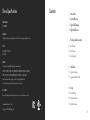
Contents
Specifications
PART NUMBER
LCCONTROL20/D10
INPUT
120-277VAC, 50/60Hz
<2W (Standby - 4W (Active)
MAXIMUM SWITCHED LOAD RATINGS
For Control of Magnetic, Electronic Ballast or LED
277VAC: 20A Magnetic/Resistive
240VAC: 5A Tungsten/Electronic, 20A FLA/
60 LRA, 2HP
120VAC: 15A Tungsten, 1HP
OPERATING TEMPERATURE
-40ºC to +40ºC
OVERALL DIMENSIONS
1.55" diameter, 5.75" length
1/2" NPT Mount, Male
16AWG pigtails
WIRELESS RANGE
Warranty is active as long as service plan is active
Class 2
IP66 Rated
Indoor and Outdoor Rated
Wet and Damp Location
Plenum Rated
Lightcloud Controller
Instruction Manual
Wire Nuts
NPT Nut O-ring
x 4 x 2
Line-of-Sight: 1000 feet
Obstructions: 100 feet

What You Need
Lightcloud Gateway
A Lightcloud installation requires
at least one Lightcloud Gateway
to manage your devices.
1 (844) LIGHTCLOUD
or 1 (844) 544-4825
WE’RE HERE TO HELP:

Wiring
SWITCHED NEUTRAL
The “Switched Neutral” white with
red stripe wire is the neutral line
for the load being switched.
This enables power measurement.
See the Power Measurement
section under “Functionality” for
more information.
BLACK
WHITE/RED
0-10V DIMMING
Panel
Controller
Lightcloud
™
Load
BLACK / HOT
WHITE / NEUTRAL
WHITE
BLACK
RED
WHITE
PURPLE
GRAY
PURPLE
GRAY

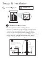
Setup & Installation
1
OFF
WARNING
OFF
Turn o power
Find a Suitable Location
1a
Use these guidelines when installing devices:
• If there is a clear line of sight between two Lightcloud
devices, they can be placed up to 1000 feet apart.
• If the two devices are separated by ordinary drywall
construction, try to keep them within 100 ft. of each other.
• Brick, concrete and steel construction may require
additional Lightcloud devices to go around the obstruction.
Lightcloud Gateway
<= 100 ft.
Add an additional Lightcloud
Device to extend network range
around corners
BRICK ,
CONC R E TE O R
ME TA L WA L L
DRY WA L L
OR SIMIL A R
Page is loading ...
Page is loading ...
Page is loading ...
Page is loading ...
Page is loading ...
Page is loading ...
Page is loading ...
Page is loading ...
Page is loading ...
Page is loading ...
Page is loading ...
Page is loading ...
Page is loading ...
Page is loading ...
Page is loading ...
Page is loading ...
Page is loading ...
Page is loading ...
Page is loading ...
Page is loading ...
Page is loading ...
Page is loading ...
Page is loading ...
Page is loading ...
Page is loading ...
Page is loading ...
Page is loading ...
Page is loading ...
Page is loading ...
Page is loading ...
Page is loading ...
Page is loading ...
Page is loading ...
Page is loading ...
Page is loading ...
Page is loading ...
Page is loading ...
Page is loading ...
Page is loading ...
Page is loading ...
Page is loading ...
Page is loading ...
Page is loading ...
Page is loading ...
Page is loading ...
Page is loading ...
Page is loading ...
-
 1
1
-
 2
2
-
 3
3
-
 4
4
-
 5
5
-
 6
6
-
 7
7
-
 8
8
-
 9
9
-
 10
10
-
 11
11
-
 12
12
-
 13
13
-
 14
14
-
 15
15
-
 16
16
-
 17
17
-
 18
18
-
 19
19
-
 20
20
-
 21
21
-
 22
22
-
 23
23
-
 24
24
-
 25
25
-
 26
26
-
 27
27
-
 28
28
-
 29
29
-
 30
30
-
 31
31
-
 32
32
-
 33
33
-
 34
34
-
 35
35
-
 36
36
-
 37
37
-
 38
38
-
 39
39
-
 40
40
-
 41
41
-
 42
42
-
 43
43
-
 44
44
-
 45
45
-
 46
46
-
 47
47
-
 48
48
-
 49
49
-
 50
50
-
 51
51
-
 52
52
-
 53
53
-
 54
54
-
 55
55
-
 56
56
-
 57
57
-
 58
58
-
 59
59
-
 60
60
-
 61
61
-
 62
62
-
 63
63
-
 64
64
-
 65
65
-
 66
66
-
 67
67


RAB Lighting EZPAN2X4-30N/D10/LC Operating instructions
- Type
- Operating instructions
Ask a question and I''ll find the answer in the document
Finding information in a document is now easier with AI
Related papers
-
RAB Lighting LCDAYLIGHT Operating instructions
-
RAB Lighting VANLED20/LC Operating instructions
-
RAB Lighting IVAT2-45LWM750GU/7PR/LC Operating instructions
-
RAB Lighting FXLED300SFYB46W/D10/LC Operating instructions
-
-
-
-
RAB Lighting WP3LED55NW/480/LC Operating instructions
-
RAB Lighting ALED4T150NW/D10/LC Operating instructions
-
RAB Lighting ALED5S150Y/D10/LC Operating instructions