Page is loading ...


2
Introduction
Dash Design 2.0 is a powerful tool used to create and edit AEM CD-X dash setups. The graphics design possibilities are extensive and this help
documentation is not intended to cover all possible options. It will provide an overview of tools and features. An interactive help feature is included
in the application. Hovering your mouse over certain target areas will trigger a tool tip that contains helpful information. There are two versions of
this document, a System User Guide and a Quick Start Guide. The Quick Start Guide is a subset of the information found in the System User
Guide. Both documents are installed with the software and can be found at the following location: \Documents\AEM\DashDesign\Instructions.
Additionally, the Windows online help feature located in the Help menu contains the exact same content.
Quick Start
AEM DashDesign 2 is distributed as a single install executable. To install, visit aemelectronics.com and click on Software Downloads and
navigate to CD Dash/DashDesign. Download the software and then run the AEM DashDesign Setup.exe and follow the on-screen instructions
including restarting computer if prompted to do so. If using the logging version of dash, also download and install AEMdata for downloading and
analyzing data logs.
Follow the on screen prompts to install the application. Double click the shortcut to launch AEM Dash Design.

3
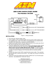
Infinity 71XX
If using an AEM supplied Infinity harness, simply plug
the 4 pin Deutsch DTM connector from the dash harness
into the corresponding connector on the Infinity harness
labeled AEMNet. If using a custom designed harness,
see the System User Guide Electrical & Wiring
section for details. Note that a switched, 12V power
source at the AEMNet connector is required for proper
function of the Dash.
1. Be sure you have the latest software installed.
2. Connect the Dash to your PC using the supplied
USB connector.
3. Turn the key on. Ensure the dash is powered up.
4. In the DashDesign software, go to Tools | Upload
Firmware. The firmware files are located at
\Documents\AEM\DashDesign\Firmware with the
format CD-14x25.bin where x25 is an example
version. See Updating the Firmware Version in
the System User Guide for more detail.
5. In the DashDesign software, go to File | Open… and
navigate to the library of pre-configured setup files for
the Infinity. They are installed at the following
location. \Documents\AEM\DashDesign\Setups\App
Specific\AEM Infinity. Choose your file and click
Open. See Uploading a Setup File in the
System User Guide for more detail.
61
69
67

4
Series 2 or EMS-4
See Series II user documentation for location of the
CAN1L and CAN1H circuits. Following is a pinout of the
4 pin Deutsch DTM connector on the Dash harness.
Connect the CAN1H circuit from your Series II ECU to
Pin 1 AEMNet CAN+. Connect the CAN1L circuit from
your Series II ECU to Pin 2 AEMNet CAN-. Use optional
AEM PN 35-2626 as mating connector.
1. Be sure you have the latest software installed.
2. Connect the Dash to your PC using the supplied
USB connector.
3. Turn the key on. Ensure the dash is powered up.
4. In the DashDesign software, go to Tools | Upload
Firmware. The firmware files are located at
\Documents\AEM\DashDesign\Firmware with the
format CD-14x25.bin where x25 is an example
version. See Updating the Firmware Version in
the System User Guide for more detail.
5. In the DashDesign software, go to File | Open… and
navigate to the library of pre-configured setup files for
the AEM Series2 & EMS-4. They are installed at the
following location.
\Documents\AEM\DashDesign\Setups\App
Specific\AEM Series2 & EMS-4. Choose your file
and click Open. See Uploading a Setup File in
the System User Guide for more detail.
The AEMNet CAN output must be enabled in your Series
II ECU before the dash can receive messages.
1. In AEMTuner, select Wizards | Setup Wizard and
choose Telemetry: AEMNet from the Wizard Types
column.
2. Left click on the Configuration Name AEMNet
Datastream and click the Apply button to enable.
69
67

5
Series 1 ECU
The Series 1 ECU uses RS232 Serial Communications to send
data to the dash. This requires the user to use the AEM 30-2228,
Serial2CAN Adapter for the Series 1 ECU.
The Serial Telemetry must be enabled on the Series 1 ECU. This is
done using the AEMPro Software.
Note: The serial datastream will only work with version 1.19 or
newer firmware. When connected to the EMS, the firmware version
is shown in the blue strip at the top of the screen. If your ECU is
not running version 1.19 or later, you can download the required
files from the aemelectronics.com website.
1. Open AEM Pro and connect to the EMS. Wait for the EMS to
finish downloading.
2. Left click on “VIEW” and select the telemetry wizard from the
wizards drop down menu.
3. In the telemetry wizard, left click on “AEM Serial Datastream
Gauge: and click OK. Close AEM Pro.
4. Connect the adapter to the EMS, and cycle power to the EMS.
The EMS is now configured to output data to the gauge.
Since the Serial2CAN adapter shares the comms port with the PC
communications cable, the ECU will always start in PC Comms
mode when the power is cycled. If the ECU does not sense
communications with a PC immediately it will then revert to data
telemetry output. To initialize PC comms after the ECU has
switched to telemetry mode you will need to power cycle the ECU.
The Serial2CAN adapter makes the Serial output from any AEM
Series 1 ECU look like the CAN output of an AEM Series 2 ECU.
So the fastest way to get something working on the dash is to use
the AEM created setups for the Series 2 ECU. With the install of
DashDesign2 on your computer there are many different base
setups you can choose from.

6
22 Channel CAN Sensor Module
1. Reference simplified connection diagram at right.
2. Be sure you have the latest software installed.
3. Connect the Dash to your PC using the supplied
USB connector.
4. Turn the key on. Ensure the dash is powered up.
5. In the DashDesign software, go to Tools | Upload
Firmware. The firmware files are located at
\Documents\AEM\DashDesign\Firmware with the
format CD-14x25.bin where x25 is an example
version. See Updating the Firmware Version
in the System User Guide for more detail.
6. In the DashDesign software, go to File | Open…
and navigate to the library of pre-configured setup
files for the 22 Channel CAN Sensor Module.
They are installed at the following location:
\Documents\AEM\DashDesign\Setups\App
Specific\AEM 30-2212 22 Ch CAN Sensor
Module. Choose your file and click Open. See
Uploading a Setup File for more detail.
7. Alternatively, you may append a .dbc file for the
22 Channel CAN Sensor Module onto your
existing setup. See the Managing DBC File
Imports section for more detail. .dbc files for
the 22 Channel CAN Sensor Module are located
in the \Documents\AEM\DashDesign\CAN folder.
They will have AEM 30-2212 in the filename.
6 Channel CAN Sensor Module
1. Reference simplified connection diagram at right.
2. Be sure you have the latest software installed.
3. Connect the Dash to your PC using the supplied
USB connector.
4. Turn the key on. Ensure the dash is powered up.
5. In the DashDesign software, go to Tools | Upload
Firmware. The firmware files are located at
\Documents\AEM\DashDesign\Firmware with the
format CD-14x25.bin where x25 is an example
version. See Updating the Firmware Version
in the System User Guide for more detail.
6. In the DashDesign software, go to File | Open…
and navigate to the library of pre-configured setup
files for the 6 Channel CAN Sensor Module. They
are installed at the following location:
\Documents\AEM\DashDesign\Setups\App
Specific\AEM 30-2226 6 Ch CAN Sensor
Module. Choose your file and click Open. See
Uploading a Setup File for more detail.
7. Alternatively, you may append a .dbc file for the 6
Channel CAN Sensor Module onto your existing
setup. See the Managing DBC File Imports
section for more detail. .dbc files for the 6
Channel CAN Sensor Module are located in the
\Documents\AEM\DashDesign\CAN folder. They
will have AEM 30-2226 in the filename.
69
67
17
69
67
17

7
8 Channel K-Type EGT CAN Module
1. Reference simplified connection diagram at right.
2. Be sure you have the latest software installed.
3. Connect the Dash to your PC using the supplied
USB connector.
4. Turn the key on. Ensure the dash is powered up.
5. In the DashDesign software, go to Tools | Upload
Firmware. The firmware files are located at
\Documents\AEM\DashDesign\Firmware with the
format CD-14x25.bin where x25 is an example
version. See Updating the Firmware Version
in the System User Guide for more detail.
6. In the DashDesign software, go to File | Open…
and navigate to the library of pre-configured setup
files for the 6 Channel CAN Sensor Module. They
are installed at the following location:
\Documents\AEM\DashDesign\Setups\App
Specific\AEM 30-2224 8 Ch EGT. Choose your
file and click Open. See Uploading a Setup
File in the System User Guide for more
detail.
7. Alternatively, you may append a .dbc file for the
8 Channel EGT onto your existing setup. See
the Managing DBC File Imports in the
System User Guide for more detail. .dbc files for
the 8 Channel EGT are located in the
\Documents\AEM\DashDesign\CAN folder. They
will have AEM 30-2224 in the filename.
Vehicle Dynamics Module
1. Reference simplified connection diagram at right.
2. Be sure you have the latest software installed.
3. Connect the Dash to your PC using the supplied
USB connector.
4. Turn the key on. Ensure the dash is powered up.
5. In the DashDesign software, go to Tools | Upload
Firmware. The firmware files are located at
\Documents\AEM\DashDesign\Firmware with the
format CD-14x25.bin where x25 is an example
version. See Updating the Firmware Version
in the System User Guide for more detail.
6. Append a .dbc file for the Vehicle Dynamics
Module onto your existing setup. See the
Managing DBC File Imports in the System
User Guide for more detail. .dbc files for the
Vehicle Dynamics Module are located in the
\Documents\AEM\DashDesign\CAN folder. They
will have AEM 30-2203 in the filename.
69
67
17
69
17

8
GPS Module
1. Reference simplified connection diagram at right.
2. Be sure you have the latest software installed.
3. Connect the Dash to your PC using the supplied
USB connector.
4. Turn the key on. Ensure the dash is powered up.
5. In the DashDesign software, go to Tools | Upload
Firmware. The firmware files are located at
\Documents\AEM\DashDesign\Firmware with
the format CD-14x25.bin where x25 is an
example version. See Updating the Firmware
Version in the System User Guide for more
detail.
6. Append a .dbc file for the GPS Module onto your
existing setup. See the Managing DBC File
Imports in the System User Guide for more
detail. .dbc files for the GPS Module are located
in the \Documents\AEM\DashDesign\CAN
folder. They will have AEM 30-2203 in the
filename.
69
17

9
OBDII
1. Be sure you have the latest software installed.
2. Connect the Dash to your PC using the supplied
USB connector.
3. Turn the key on. Ensure the dash is powered up.
4. In the DashDesign software, go to Tools | Upload
Firmware. The firmware files are located at
\Documents\AEM\DashDesign\Firmware with the
format CD-14x25.bin where x25 is an example
version. See Updating the Firmware Version in
the System User Guide for more detail.
5. In the DashDesign software, go to File | Open… and
navigate to the library of pre-configured setup files for
OBDII. They are installed at the following location.
\Documents\AEM\DashDesign\Setups\App
Specific\OBDII. Choose your file and click Open.
See Uploading a Setup File in the System User
Guide for more detail.
To configure your dash for OBDII data display, the dash
must scan your vehicle's OBDII port to identify all ECUs
and available PIDs. PID stands for Parameter ID. These
are codes used to request specific data from a vehicle.
Connect the OBDII interface cable to your vehicle's
OBDII connector. To begin the scan process, launch
AEM DashDesign and go to Tools | Scan Vehicle
OBDII...
Click Scan and follow the on screen prompts. See OBDII
PID Scan in the System User Guide for more detail.
3rd Party Hardware
AEM has validated CAN setups for many 3rd party hardware platforms. For a continuously updated list of validated setups, please visit our forum
at https://www.aemelectronics.com/?q=forum/can-configurations-3rd-party-hardware
69
67
64

10

11
Workflow Tips
RECOMMENDED STEPS
The basic workflow for creating a new setup or editing
an existing setup:
1. CAN messages must exist before they can be
displayed on screens. See the CAN Tab
section for more information.
2. Basic setup parameters are defined using the
Setup Tab . These include things like shift lights
and screen brightness.
3. The Images Tab is used to import all graphic
assets for use in your setup.
4. Use the Channels Tab to define custom
channel names for CAN messages or to create
your own custom channels from scratch.
5. Alarm channels must be defined before they can be
used as inputs to display items. See the Alarm
Tab section for more detail.
6. Once all graphics, alarms and channels are
defined, edit existing screens or design your own
using the Design Tab .
7. If your dash hardware is equipped with internal
logging, configure your logging preferences using
the Logger Tab .
8. Finally, use the Simulate Tab to test your
setup. Simulate channel data and watch your
screens come to life right on your PC screen.
9. Save your setup and upload it to your dash. See
the Uploading a Setup File section.
Menus
File
New Setup... Creates a new Setup file from scratch
Open Setup... Opens an existing Setup file
Recent Files is a list of recently opened Setup files
Save Setup saves the existing Setup file to disk
Save Setup As...saves the existing Setup file to disk with a new name
Save New Version saves the existing Setup file to disk with an automatically
incremented suffix number.
Upload to Display loads the existing setup onto a CD-X dash. The PC must be
connected to the dash with the included USB cable and the dash must be
powered on. See Uploading a Setup File for more details.
Download From Display saves a Setup file to disk that is currently loaded onto a
CD-X dash. See Downloading a Setup File for more details. The PC must
be connected to the dash with the included USB cable and the dash must be
powered on.
Unlock Layout unlocks the layout so gauge items can be edited.
Exit exits the program.
14
18
21
23
21
33
41
42
67
67
68

12
Edit
Undo removes the last edit
Redo reapplies an edit that was previously undone
History displays a running log of recorded edits. See the Edit History
section for more detail.
Cut cuts a selection
Copy copies a selection
Paste pastes a selection
Delete deletes a selection
Select All selects all items on the current screen
Select None deselects all previously selected items
Group, Ungroup, Raise, Lower, Raise to Top, Lower to Bottom - See the Screen
Editing section for more details.
Screen
Clear Screen removes all items from the current screen.
Duplicate Screen launches a dialog that allows you to copy all items from any
screen in the setup to the current screen.
Import Screen replaces all items in the current screen with items from any
screen that exists within any setup on your PC.
Select Screen launches a selection dialog window that allows screen selection.
See the Pages section for more details.
View
Toggle Fullscreen Mode displays the window full screen
Reset Workspace Layout resets the layout of windows docked to the edges of
the frame
Tools
Program Clock synchronizes the CD-X internal hardware clock with the clock on
your PC. See the Program Clock section for more details.
Upload Firmware...reprograms the CD-X with a different firmware file. Firmware is
the internal operating system. See the Updating the Firmware Version
section for more details.
Scan Vehicle OBDII...initiates a utility that probes the vehicle for available OBDII
CAN messages. See the OBDII PID Scan section for more details.
40
33
33
68
69
64

13
Configure
Unit Preferences...allows the user to set global unit preferences.
For each quantity, a list of unit preferences is available.
Select from the drop down list.
Keyboard Shortcuts...may be customized as desired. Actions available for customization are
available through the Keyboard Shortcuts...menu.
Toggle Dark Theme...allows the user to toggle between a light a dark theme. A restart is required.
Help
The Help... menu will launch a version of this document.
About Dash Design... will display application version info.

14
Main Tabs Overview
Twelve main tabs are used to create and edit a dash display
setup. The tabs are accessible via vertically arranged icons
on the left hand side of the window.
Screens - managing screens and creating and configuring
graphical gauge elements
Design - Select, place and edit screen elements
Simulator - Dynamically simulate your configuration
Channels - editing value based channels
Alarms - define channel based logic that controls the dash
alarm indicators
Warning Messages - Create and edit warning messages for
display
Timers - Create and edit timers for display
CAN - define CAN receive and transmit channels
Logger - define internal logger channels and trigger criteria
Images - Library for all images used in the configuration
Image Selectors - Create and edit image selectors
Setup - define miscellaneous hardware features
CAN Tab
The AEM CD-X series dashes are designed to display CAN message data. The CAN setup must be defined in order to display data on screens.
DashDesign2 includes a feature for automatically importing pre-configured CAN setups. These setups have either a .dbc or .aemcan file
extension. Available files will be installed in the \Documents\AEM\DashDesign2\CAN directory.
The Show menu selects which Port to display and edit. There are two CAN ports
available on CD-X dashes.
The Baudrate menu sets the data transmit rate for the selected bus.
IMPORTANT: All devices on a given CAN port must be set to the same value or
the bus will not function.
The Termination Resistor check box enables the internal 120 ohm termination
resistor for the selected CAN port. Every physical CAN bus needs to have 2
termination resistors installed, one on each physical end of the bus.
Normal Mode means this port operates as a normal CAN bus port. OBDII Mode
means this port is used exclusively to receive CAN Based OBDII Vehicle
Parameters (J1979 Mode 1 PIDs). Click the Import OBDII Scan...button to
configure OBDII CAN channels.

15
Off disables the unique Motec hundred series CAN support.
Set 1 configures this port to receive a Motec M800 Dataset 1 CAN stream. Most
Hundred Series ECU's (M400, M600, M800, M880), with the exception of the
M84, can send Dataset 1. Confirm the Dataset that the ECU is transmitting.
Set 3 Configures this port to receive a Motec M800 Dataset 3 CAN stream. All
Hundred Series ECU's (M84, M400, M600, M800, M880) can send Dataset 3 and
this is the preferred Motec Dataset. Confirm the Dataset that the ECU is
transmitting.
Use the ID text box to enter the base address for the selected Dataset. The
default Motec address for Dataset 1 is 0x5F0 (1520 decimal). The default Motec
address for Dataset 3 is 0x0E8 (232 decimal). IMPORTANT, Confirm the base
address that the ECU is sending the data out on and enter that value here, don't
assume the ECU is using the default values. If you want to enter the address as
a decimal number, then un-check the "Show CAN IDs in Hexadecimal" check
box lower down on the page.
Subjects all incoming message addresses to a logical mask to strip out
unwanted information. In most cases this is used to remove unique device
information and leave only a core address. If enabled, the value entered as the
mask is subjected to a logical AND with the received address and the resulting
value is treated as the CAN message address for all decoding purposes.
Address masking is not a common requirement but it is used on most of the
Holley EFI controllers which require a mask of 0xFFFFF800.
Toggles between displaying the CAN ID's as either decimal and hexadecimal
values. It is important to understand that this does not change the underlying
CAN ID value, only the way you choose to see and enter it. Most devices use
hex but a few use decimal. If you have any documentation that contains
addresses beginning with "0x" or containing any letters then it is definitely
Hexadecimal
The CAN message layout is a tabular representation of the message structure.
Click a message in the list below to update.
The Multiplexor selection box allows you to choose the specific multiplex switch
value to show for multiplexed messages.

16
AEM provides pre-configured CAN definition files. Click the Import CAN/DBC...
button. Available files will be installed in the
\Documents\AEM\DashDesign2\CAN directory.
The Clear button will remove all messages from the list.
will add a new undefined message.
will delete the selected message.
AEMNet Enabled Device Reference
If available from AEM, pre-configured setups are available within the \Documents\AEM\DashDesign\Setups base directory in the sub directory
listed in the table below. CAN DBC files are located in the \Documents\AEM\DashDesign\CAN directory.
Product Part Number
Product Name
Pre-configured Setups
.dbc files
30-2212
22 Channel CAN Sensor Module
\App Specific\AEM 30-2212 22 Ch
CAN Sensor Module
AEM 30-2212 CAN Sensor
Module20180212.dbc
30-2226
6 Channel CAN Sensor Module
\App Specific\AEM 30-2226 6 Ch
CAN Sensor Module
AEM 30-2226 CSM6 20180713.dbc
30-2224
8 Channel K-Type EGT Module
\App Specific\AEM 30-2224 8 Ch
EGT
AEM 30-2224 EGT8.dbc
30-03X0
X-Series UEGO Gauge & Inline
UEGO
Not available
AEM X-Series Gauges Rev0.dbc
AEM 30-03X0 X-Series UEGO
20161011.dbc
30-6XXX
EMS Series II
\App Specific\AEM Series2 &
EMS-4
AEM 30-6XXX EMS-V2
20161128.dbc
30-71XX
Infinity EMS
\App Specific\AEM Infinity
AEM 30-71XX Infinity
20161021.dbc
30-7108TA
Infinity EMS, TA2
\App Specific\AEM Infinity
AEM 30-7108TA TransAm TA2
Spec Infinity 20161213.dbc
30-2340
4 Channel UEGO
Not available
AEM 30-2340 4Ch UEGO
20161213.dbc
30-4900
Wideband Failsafe Gauge
Not available
AEM 30-4900 Wideband Failsafe
20161014.dbc
30-4911
Flex Fuel Failsafe Gauge
Not available
AEM 30-4911 Flex Fuel Failsafe
20161013.dbc
30-6905
EMS-4
Not available
AEM 30-6905 EMS-4
20170823.dbc
30-2203
30-2206
Vehicle Dynamics Module
Not available
AEM 30-2203 VDM 20161018.dbc
AEM 30-2206 VDM 20190312.dbc
30-2207
GPS Module
Not available
AEM 30-2207 GPS 20190312.dbc
30-2230
30-2231
Serial to CAN, Motec M4
\App Specific\Motec_M4
AEM 30-2230 2231
S2C_Motec_M4_Rev0.dbc

17
Product Part Number
Product Name
Pre-configured Setups
.dbc files
30-2228
Serial to CAN, AEM Series1 EMS
\App Specific\AEM Series2 &
EMS-4
AEM 30-2228
S2C_AEMS1ECU_Rev0.dbc
30-2229
Serial to CAN, Hondata KPro
\App Specific\Hondata_KPro1-3
AEM 30-2229
S2C_Hondata_KPro_Rev0.dbc
Managing DBC File Imports
The button allows you to import all
available messages or simply a subset. Expand the
menu structure as shown to see details. Toggle the
check box to the left of each message to include or
exclude. Click OK and your selection will be appended
to the CAN receive signal list.

18
Setup Tab
The setup sub tabs are accessed by clicking the icon.
Configure the seven shift light LEDs by first selecting a channel
(typically EngineSpeed [rpm])
Select an RPM threshold for each LED or alternatively, select a
starting RPM, an increment value and click Auto Populate Shift
Lights. Exceeding the last shift light by this value will cause all lights
to flash. If you simply want all LEDs to turn on and flash at the same
value, enter that number as the start value and set the increment as 0,
then click Auto Populate Shift Lights.

19
The Brightness setup dialog allows you to choose two different brightness
settings for both the screen and LEDs. 100% should only be used in direct
sunlight. 70% gives almost as much brightness without over driving the backlight.
5%-10% is appropriate for night mode. If the LEDs are directly in line with the
drivers eyes you may find the best shift light brightness settings for night mode to
be as low as 1 or 2%.
Optional lap timing features require a location reference for the start/finish line.
Select Beacon for a beacon input. Select GPS to use a GPS reference. If using
a beacon, select either Standard or AIM type.
With lap timing configured, the race vehicle can be driven on track to collect GPS
data. At the exact moment when crossing the start/finish line, the lap beacon
button should be pressed and held momentarily until both the amber and red
LEDs flash on the dash. The lap beacon button is an external input that must be
added using the violet wire input. See Electrical & Wiring . The flashing
LEDs indicate that the start/finish line GPS coordinates have been successfully
set. Each time the vehicle crosses the start/finish line, a new lap will be counted
and lap timer will reset.
Select the speed channel to use when calculating the average lap speed and the
predictive lap time.
Select channel inputs to use for GPS Latitude, Longitude and Course.
Track Width [m] is the maximum possible width at the start/finish line that the
vehicle could pass through.
This is an internal counter backed up to non-volatile memory that cannot be
reset (it is set to zero when the unit is built).
Select an input that is road speed in km per second. All AEM base setups
include an odometer scaled in both miles and kilometers.
61

20
An optional method of choosing which page should be displayed on the dash. A
page channel can be selected here and as long as it has values of 1-4 then the
dash will display those pages. Normally, the pages are changed by pressing the
left button or grounding the page increment input to the dash.
Night Mode is set whenever the Night Mode pin on the connector (Pin 9, Gray
wire) is pulled to 12V. Night mode can also be triggered via a CAN message
identified here.
Normally a given channel is only monitored if used by a gauge on the currently
displayed screen. In certain circumstances however, it is necessary to monitor
some channels regardless of whether or not they are used by the currently
displayed screen page. For example, if the maximum coolant temperature is
required as a channel for some screens, switching screens deletes the data as
the screen changes and recreates it if necessary. The maximum value is then
reset and its information is lost. By adding this channel to the monitor page it is
created when the color display is switched on. Changing screens has no effect
on the channel and the data is not reset unless a reset signal is received.
Furthermore, channels added to the monitor screen are automatically stored in
non-volatile memory. Thus, the value of a min, max or average added to the
monitor screen is preserved even when the screen is powered off.
/