Page is loading ...

EN
A
C
B
Service Manual
MX1212 & MXL1212 Pump &
Packages
Models: MX1212‡‡ & MXL1212‡‡, ‡‡=PL (PTFE/Leather), PP (PTFE), PU (PTFE/UHMWPE), UC (U-Cups)
Patent 7,603,855.
SPECIFICATION - Bare Pump
Ratio:
12:1
Maximum air inlet pressure:
8 bar [116 psi]
Maximum fluid pressure:
96 bar [1390 psi]
Displacement per cycle:
72 cc [2.4 oz]
Output @ 60 cycles/min:
4.3 l/m [1.2 US gal/m]
Air consumption @ 20 cycles/min and 8 bar [116 psi] air
inlet pressure:
147 l/m [5.2 SCFM]
Maximum recommended continuous cycle rate (cycles/min):
20
Air inlet connection:
3/8" BSP(f)
Fluid inlet connection:
MX-3/4" NPS(m), MXL-1/2" NPS(m)
Fluid outlet connection:
3/8" BSP(m)/NPS(m)
Sound level:
96.2 dB
Weight:
13 kg [28.4 lbs]
Wetted parts materials of construction:
Stainless Steel, Tunsten Carbide, Hard
Chrome, PTFE, Polyethylene, Leather,
Ceramic.
77-3205-R3.2 1/36

EN
EN ISO 4414: Pneumatic Fluid Power - General Rules and safety requirements
EN 12621: Machinery for the supply and circulation of coating materials under pressure - Safety requirements
EN1127-1: Explosive atmospheres - Explosion prevention - Basic concepts
EN 13463-1: Non electrical equipment for use in potentially explosive atmospheres - Basic methods and requirements
EN 13463-5: Non electrical equipment for use in potentially explosive atmospheres - Protection by constructional safety
Providing all conditions of safe use stated within the product manuals have been complied with and that the final equipment
into which this product is installed has been re-assessed as required, in accordance with essential health and safety
requirements of the above standards, directives and statutory instruments and also installed in accordance with any applicable
local codes of practice.
D Smith
10/2/15
EN ISO 12100: Safety of Machinery - General Principles for Design
EN ISO 4413: Hydraulic Fluid Power - General Rules and safety requirements
(General Manager)
This Product is designed for use with:
Solvent and Water based Materials
Suitable for use in hazardous area:
Zone 1 & 2
Protection Level:
II 2 G c X IIB T4 (NB 0891)
Manufacturer:
Binks,
Ringwood Road,
Bournemouth, BH11 9LH. UK
EC Declaration of Conformity
We: Binks declare that the above product conforms with the Provisions of:
Machinery Directive 2006/42/EC
ATEX Directive 94/9/EC
by complying with the following statutory documents and harmonized standards:
Product Description
MX4**, MXL4**, MX12**, MXL12**, MX190***,
MX220***, MMX4**, MMX12**
77-3205-R3.2 2/36

EN
NOTE
Hazards or unsafe practices which could result in
severe personal injury, death or substantial property
damage.
Hazards or unsafe practices which could result in
minor personal injury, product or property
damage
Important installation, operation or maintenance
information.
WARNING
Read the following warnings before using this equipment.
READ THE MANUAL. Before operating finishing equipment, read and
understand all safety, operation and maintenance information
provided in the operation manual.
AUTOMATIC EQUIPMENT. Automatic
equipment may start suddenly without
warning.
WEAR SAFETY GLASSES. Failure to wear safety glasses with side
shields could result in serious eye injury or blindness.
PROJECTILE HAZARD. You may be
injured by venting liquids or gased that
are released under pressure, or flying
debris.
DE-ENERGIZE, DE-PRESSURISE, DISCONNECT AND LOCK OUT ALL
POWER SOURCES DURING MAINTENANCE. Failure to de-energize,
disconnect and lock out all power supplies before performing
equipment maintenance could cause serious injury or death.
KNOW WHERE AND HOW TO SHUT
OFF THE EQUIPMENT IN CASE OF AN
EMERGENCY.
NOISE LEVELS. The A-weighted sound level of pumping and spray
equipment may exceed 85 dB(A) depending on equipment settings.
Actual noise levels are available on request. It is recommended that
ear protection is worn at all times while equipment is in use.
PRESSURE RELIEF PROCEDURE.
Always follow the pressure relief
procedure in the equipment instruction
manual.
INSPECT THE EQUIPMENT DAILY. Inspect the equipment for worn or
broken parts on a daily basis. Do not operate the equipment if you
are uncertain about its condition.
OPERATOR TRAINING. All personnel
must be trained before operating
finishing equipment.
EQUIPMENT MISUSE HAZARD. Equipment misuse can cause the
equipment to rupture, malfunction or start unexpectedly and result in
serious injury.
PACEMAKER WARNING. You are in the
presence of magnetic fields which may
interfere with the operation of certain
pacemakers.
HIGH PRESSURE CONSIDERATION. High pressure can cause serious
injury. Relieve all pressure before servicing. Spray from the gun,
hose leaks or ruptured components can inject fluid into your body
and cause extremely serious injury.
KEEP EQUIPMENT GUARDS IN PLACE.
Do not operate the equipment if the
safety devices have been removed.
STATIC CHARGE. Fluid may develop a static charge that must be
dissipated through proper grounding of the equipment, objects to be
sprayed and alll other electrically conductive objects in the dispensing
area. Improper grounding or sparks can cause a hazardous condition
and result in fire, explosion or elecrtic shock and other serious injury.
NEVER MODIFY THE EQUIPMENT. Do
not modify the equipment unless the
manufacturer provides written
approval.
PROP 65 WARNING. WARNING:This product contains chemicals
known to the state of California to cause cancer and birth defects or
other reproductive harm.
PINCH POINT HAZARD. Moving parts
can crush and cut. Pinch points are
any areas where ther are moving
parts.
IT IS THE RESPONSIBILITY OF THE EMPLOYER TO PROVIDE THIS INFORMATION TO THE
OPERATOR OF THE EQUIPMENT.
In this part sheet, the words WARNING, CAUTION and NOTE are used to emphasize important safety information as
follows:
WARNING
CAUTION
77-3205-R3.2 3/36

EN
1
4
6
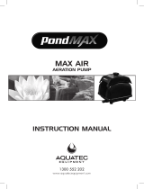
PUMP OPERATION AND CLEANING
AIR SUPPLY
2
AIR SHUT OFF VALVE (IF FITTED)
WARNING
WARNING
WARNING
3
AIR PRESSURE REGULATOR
BINKS PUMP
5
FLUID PRESSURE RELIEF VALVE (IF FITTED)
SPRAY GUN
7
FLUID FILTER (IF FITTED)
8
LUBRICATION CUP & LEVEL
9
EARTH CABLE AIR MOTOR
10
EARTH CABLE FLUID FILTER (IF FITTED)
11
FLUID SUCTION HOSE/SUCTION
TUBE/GRAVITY HOPPER - DEPENDING ON
MODEL
12
AIR PRESSURE REGULATOR (SPRAY GUN)
(IF FITTED)
13
LUBRICANT
0114-016099 SOLVENT BASED MATERIALS
0114-016100 WATER BASED MATERIALS
14
RELIEF/RETURN HOSE (IF FITTED)
15
FLUID CONTAINER
WEAR EYE PROTECTION WHEN OPERATING THIS EQUIPMENT
PUMP MUST BE GROUNDED BEFORE OPERATING, TO PREVENT STATIC CHARGES.
HOSES MUST HAVE A SUITABLE WORKING PRESSURE ABOVE THE MAXIMUM
PRESSURE POSSIBLE.
77-3205-R3.2 4/36

INSTALLATION
1 - ENSURE THE PUMP IS LOCATED ON A SUITABLE & STABLE MOUNTING.
2 - GROUND/EARTH THE PUMP WITH (9) OR (10), CHECK EARTH IS LESS THAN 1 Ohm.
3 - CONNECT SUITABLE HOSES FOR AIR SUPPLY AND FLUID HOSE TO GUN.
4 - FILL THE LUBRICATION CUP (8) WITH A SUITABLE LUBRICANT (13) SO IT IS VISIBLE IN THE LEVEL SIGHT
GLASS.
5 - ENSURE SUITABLE FILTER MESH (100 MESH, 150 µm STD) IS INSTALLED IN THE FILTER(7).
6 - ENSURE RETURN HOSE (14) IF FITTED, IS DIRECTED INTO THE FLUID CONTAINER (15).
CLEANING THE PUMP
NOTE
THE PUMP HAS BEEN TESTED WITH OIL, WATER OR OTHER MATERIAL. CLEAN THE
PUMP PRIOR TO USE TO AVOID ANY CONTAMINATION.
1 - INSERT SUCTION SYSTEM (11) & RETURN HOSE (14) (IF FITTED) INTO A CONTAINER WITH SUITABLE
CLEANING FLUID.
2 - CLOSE VALVE (2) AND SET REGULATORS (3) & (12) TO ZERO ( WIND ANTICLOCKWISE), OPEN VALVE (5) IF
FITTED.
3 - REMOVE FLUID NOZZLE FROM THE SPRAY GUN FOR RETURNING FLUID INTO THE CONTAINER
4 - CONNECT AIR SUPPLY
a) IF (5) IS FITTED:
5a - OPEN VALVE (2), INCREASE REGULATOR PRESSURE (3) UNTIL PUMP STARTS TO OPERATE (APPROX. 1
BAR [14.5 PSI])
6a - ALLOW FLUID TO CIRCULATE FOR SEVERAL MINUTES OR UNTIL SYSTEM IS CLEAN.
7a - CLOSE VALVE (5) AND TRIGGER SPRAY GUN INTO CONTAINER FOR SEVERAL MINUTES TO CLEAN HOSE &
GUN.
8a - WITH THE TRIGGER STILL OPEN REDUCE REGULATOR PRESSURE (3) TO ZERO, AND OPEN VALVE (5) IF
FITTED AND CLOSE TRIGGER.
b) IF (5) IS NOT FITTED.
5b - TRIGGER SPRAY GUN AND HOLD OVER CONTAINER, INCREASE REGULATOR PRESSURE (3) UNTIL PUMP
STARTS TO OPERATE (APPROX. 1 BAR [14.5PSI])
6b - ALLOW FLUID TO CIRCULATE FOR SEVERAL MINUTES OR UNTIL SYSTEM IS CLEAN.
7b - WITH THE TRIGGER STILL OPEN REDUCE REGULATOR PRESSURE(3) TO ZERO AND ENSURE NO PRESSURE
IS LEFT IN THE HOSE AND GUN BEFORE CLOSING THE TRIGGER.
NOTE
REPEAT CLEANING PROCESS UNTIL CLEANING FLUID HAS NO CONTAMINATION, ESPECIALLY IF
THE PUMP WILL NOT BE USED IMMMEDIATELY, OR HAS BEEN USED WITH 2 COMPONENT PAINTS.
CAUTION
WHEN THE SPRAY GUN IS NOT IN USE THE SAFTEY LOCK SHOULD BE ENGAGED TO PREVENT
ACCIDENTAL OPERATION.
77-3205-R3.2 5/36

SHUT DOWN
STARTUP
1 - INSERT SUCTION SYSTEM (11) & RETURN HOSE (14) (IF FITTED) INTO A CONTAINER WITH THE FLUID TO
BE SPRAYED
2 - CLOSE VALVE (2) AND SET REGULATORS (3) AND (12) TO ZERO (WIND ANTICLOCKWISE), OPEN VALVE (5)
IF FITTED.
3 - REMOVE SPRAY TIP FROM THE GUN FOR RETURNING FLUID INTO THE CONTAINER.
4 - CONNECT AIR SUPPLY.
a) IF (5) IS FITTED
5a - OPEN VALVE (2), INCREASE REGULATOR PRESSURE (3) UNTIL PUMP STARTS TO OPERATE.
6a - WHEN FLUID FLOWS THROUGH HOSE (14) WITHOUT AERATION, CLOSE VALVE (5).
7a - OPEN SPRAY GUN TRIGGER UNTIL FLUID FLOWS INTO CONTAINER WITHOUT AIR, THEN RELEASE
TRIGGER.
b) IF (5) IS NOT FITTED.
5b - TRIGGER THE SPRAY GUN AND HOLD OVER CONTAINER, INCREASE REGULATOR PRESSURE (3) UNTIL
PUMP STARTS TO OPERATE.
6b - KEEP TRIGGER OPEN UNTIL FLUID FLOWS INTO CONTAINER WITHOUT AERATION, THEN RELEASE
TRIGGER.
8 - REDUCE REGULATOR PRESSURE (3) TO ZERO.
9 - APPLY SPRAY GUN SAFETY LOCK WHILE SPRAY TIP IS FITTED.
10 - INCREASE REGULATOR PRESSURE(3) UNTIL DESIRED ATOMISATION IS ACHIEVED FROM SPRAY GUN.
11 - INCREASE REGULATOR PRESSURE (12) TO ACHIEVE DESIRED SPRAY FAN.
1 - REDUCE REGULATOR PRESSURE (3) AND (12) TO ZERO.
2 - TRIGGER GUN TO REDUCE SYSTEM PRESSURE.
3 - OPEN VALVE (5) SLOWLY IF FITTED.
4 - APPLY SPRAY GUN SAFETY LOCK WHILE SPRAY TIP IS REMOVED
5 - TRIGGER GUN CAREFULLY INTO CONTAINER AND ENSURE FLUID SYSTEM IS DE-PRESSURISED.
6 - CLOSE VALVE(2) AND REMOVE AIR SUPPLY.
7 - APPLY SPRAY GUN SAFETY LOCK.
8 - CLEAN AS INSTRUCTED AND SOAK/CLEAN SPRAYGUN FLUID NOZZLE.
NOTE
IF THE SYSTEM IS NOT USED FOR AN EXTENDED PERIOD IT IS RECOMMENDED TO BE FILLED
WITH A LIGHT OIL AFTER CLEANING.
77-3205-R3.2 6/36

EN
PL PP PU UC
1
1 1 1 1
1 - - -
- 1 - -
- - 1 -
- - - 1
3
∆ 3 3 3 3
4
3 3 3 3
5 1 1 1 1
6 • 2 2 2 2
7 1 1 1 1
9
1 1 1 1
∆
0114-011798
GROUND WIRE
•
Part only available in repair kits: 0115-010305, 0115-010307,0115-010309 and 0115-010387.
Part only availble in AX85 Hardware kit: 0115-010213.
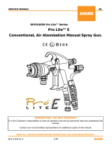
MX1212 & MXL1212
FX12PL/FXL12PL
FLUID SECTION (PTFE/LEATHER)
FX12PP/FXL12PP
FLUID SECTION (PTFE)
FX12PU/FXL12PU
FLUID SECTION (PTFE/UHMW)
FX12UC/FXL12UC
FLUID SECTION (U-CUPS)
SOCKET HEAD CAP SCREW
ITEM
PART NUMBER
DESCRIPTION
QUANTITY
AX85S
AX85S AIR MOTOR
2
0115-010001
MOTOR ROD ADAPTER
LOCKING CLIP
GUARD
MX1212 & MXL1212 BARE PUMP
0115-010646
0115-010113
0115-010655
8
166001
SLOTTED SET SCREW
3
3
3
3
TIE ROD
0115-010649
77-3205-R3.2 7/36

EN
ITEM NUMBER
MAINTENANCE ORDER (Reverse for assembly)
PETROLEUM JELLY
THREAD SEALANT (PTFE tape)
MAINTENANCE SYMBOLS
MX1212 & MXL1212 BARE PUMP - MAINTENANCE
RECOMMENDED LUBRICANT LEVEL
77-3205-R3.2 8/36

EN
Worn or dirty upper packings.
Replace or clean upper packings as
necessary.
Pump does not stop on the down
stroke.
Worn or dirty lower ball check.
Replace or clean the parts as
necessary.
Pump does not stop on the up
stroke.
Worn or dirty upper ball check.
Worn or dirty lower packings.
Replace or clean the parts as
necessary.
Pump runs erratically
Blocked siphon kit.
Blocked inlet filter or strainer.
Low material level.
Replace or clean the siphon kit.
Replace or clean the inlet filter or
strainer.
Replace or refill material container.
Pump runs , with no output.
Check that all connections are tight.
Replace or clean the parts as
necessary.
Loose connection in between pump
and siphon kit.
Stuck lower ball.
MX1212 & MXL1212 BARE PUMP - TROUBLESHOOTING
PROBLEM
CAUSE
SOLUTION
Pump will not start
No compressed air.
Spray tip is blocked.
Check compressed air supply.
Clean or replace the spray tip.
Erratic operation of air motor,
air motor stops.
Worn poppet assemblies.
Worn or dirty spool and sleeve
assembly.
Replace the poppet assemblies.
Clean or replace the spool and sleeve
assembly, as necessary.
Continuous air leak from the
exhaust
Worn poppet assemblies.
Worn piston seal.
Worn diaphragm.
Replace poppet assemblies.
Replace piston seal.
Replace diaphragm.
Material in solvent cup.
77-3205-R3.2 9/36

EN
Patent 7,603,855
Piston Diameter:
85 mm [3.3 in]
Stroke Length:
75 mm [3.0 in]
3/8" BSP(f)
AX85S Air Motor
SPECIFICATION
Maximum air inlet pressure
8 bar [116 psi]
Maximum recommended continous cycle rate: (cycles/min)
20
Air inlet connection:
77-3205-R3.2 10/36

EN
●
◊
□
∆
THREAD SEALANT (PTFE tape)
Parts are included in 0115-010215 AX85 Repair Kit
Parts are included in 0115-010217 AX85 Seal Kit
Parts are included in 0115-010226 Air Motor Valve Repair Kit
Parts are included in 0115-010213 AX85 Hardware Kit.
MAINTENANCE SYMBOLS
ITEM NUMBER
DISASSEMBLY ORDER
(Reverse order for assembly)
PETROLEUM JELLY/GREASE
AX85S AIR MOTOR
77-3205-R3.2 11/36

EN
1
○
1
2
○
1
3
○∆
4
4
○∆
BUTTON HEAD CAP SCREW 8
5
○
2
6
○+§□
2
7
○+□
2
8
○∆
4
9
○
1
10
○∆
1
11
○□
2
13
○□
2
14
○+□
2
15
○□
1
16
○
1
17
○+§□
4
18
+§□
4
19
+
2
20
1
21
∆
4
22
+§
2
23
1
24
∆
1
25
+§
1
26
∆
2
27
1
28
+§
1
29
1
30
1
31
+
1
○
+
§
□
∆
REF.
PART NUMBER
DESCRIPTION
QTY
BUTTON HEAD CAP SCREW
0115-010657
MOTOR ROD CARTRIDGE ASSEMBLY
Parts are included in 0115-010213 AX85 Hardware Kit.
0115-010029
SOCKET HEAD CAP SCREW
0115-010050
CYLINDER SEAL, 85mm
0115-010003
CYLINDER, 85mm
0115-010096
LOCKNUT
0115-010036
SEALING RING
0114-014774
SAFETY VALVE
0115-010049
O-RING
0115-010051
O-RING
Items available separately or as a complete assembly: 0115-010660.
Parts are included in 0115-010215 AX85 Repair Kit.
Parts are included in 0115-010217 AX85 Seal Kit.
Parts are included in 0115-010226 Air Motor Valve Repair Kit.
0115-010035
FLAT WASHER
0115-010336
PISTON, 85mm
0114-014466
PISTON SEAL, 85mm
0115-010034
MOTOR ROD
0115-010006
LOWER END CAP MACHINING
0115-010037 ●
POPPET ASSEMBLY
0115-010004
UPPER END CAP MACHINING
0115-010107
PIPE PLUG
0115-010018
VALVE BLOCK END CAP
0115-010017
MAGNET
0115-010016
BUMPER
0115-010015
SPOOL AND SLEEVE ASSEMBLY
0115-010019
QUICK EXHAUST VALVE CAGE
0115-010021
O-RING
0115-010020
DIAPHRAGM
0115-010024
COUNTER SUNK CAP SCREW
0115-010097
VALVE BLOCK
0115-010023
EXHAUST COVER SCREEN
0115-010022
EXHAUST COVER
0115-010026
0115-010073
AX85S AIR MOTOR
77-3205-R3.2 12/36

EN
MAINTENANCE SYMBOLS
ITEM NUMBER
DISASSEMBLY ORDER
(Reverse order for assembly)
PETROLEUM JELLY/GREASE
THREAD SEALANT (PTFE tape)
AX85S AIR MOTOR - MAINTENANCE
77-3205-R3.2 13/36

EN
ITEM NUMBER
DISASSEMBLY ORDER
(Reverse order for assembly)
PETROLEUM JELLY/GREASE
THREAD SEALANT (PTFE tape)
AX85S AIR MOTOR - MAINTENANCE
MAINTENANCE SYMBOLS
77-3205-R3.2 14/36

EN
CAUTION
Spool and sleeve assembly (15) is a matched
set and cannot be interchanged with other
spool and sleeve assemblies
Take care when handling the magnets (13). Avoid
getting magnets in close proximity to each other.
Injury or damage to magnets may result.
(Reverse order for assembly)
WARNING
PACEMAKER WARNING. You are in
the presence of magnetic fields
which may interfere with the
operation of certain pacemakers.
NOTE
AX85S AIR MOTOR - MAINTENANCE
MAINTENANCE SYMBOLS
ITEM NUMBER
DISASSEMBLY ORDER
PETROLEUM JELLY/GREASE
THREAD SEALANT (PTFE tape)
77-3205-R3.2 15/36

EN
AX85S AIR MOTOR - TROUBLESHOOTING
PROBLEM
CAUSE
SOLUTION
Pump will not start
No compressed air.
System is blocked.
Check compressed air supply.
Clear the blockage.
Erratic operation of air
motor, air motor stops
Worn poppet assemblies.
Worn or dirty spool and sleeve
assembly.
Replace poppet assemblies.
Clean or replace the spool and sleeve
assembly as necessary.
Continuous air leak from
the exhaust
Worn poppet assemblies.
Worn piston seal.
Worn diaphragm.
Replace poppet assemblies.
Replace piston seal.
Replace diaphragm.
77-3205-R3.2 16/36

EN
248 bar
Displacement per cycle:
72 cc
Output @ 60 cycles/min:
4.3 L/m [1.1 gal/m]
Fluid inlet size:
FX-3/4" NPS(m), FXL-1/2"NPS(m)
Fluid outlet size:
3/8" BSP(m) & 3/8" NPS(m)
Weight:
6.4 kg [14.1 lbs]
Wetted parts materials of construction:
Stainless Steel,
Tungsten Carbide,
Hard Chrome, PTFE,
Polythylene, Leather, Ceramic
SPECIFICATIONS
Maximum fluid pressure:
FX12 & FXL12 FLUID SECTION
Models: MX1205‡‡ & MXL1205‡‡, ‡‡=PL (PTFE/Leather), PP (PTFE), PU (PTFE/UHMWPE), UC (U-Cups), UCU (U-
Cups/UHMWPE)
77-3205-R3.2 17/36

EN
•
+
0115-010269 CHECK VALVE
Parts are included in Repair Kits
Parts are included in Seal Kits
FX12 & FXL12 FLUID SECTION (Chevron seals)
Models: FX12‡‡ & FXL12‡‡, ‡‡=PL (PTFE/Leather), PP (PTFE), PU (PTFE/UHMWPE).
77-3205-R3.2 18/36

EN
PL PP PU
1
1 1 1
2
1 1 1
3
•+
1 1 1
4
1 1 1
5
1 1 1
6 •+
2 2 2
•+
1 - -
•+
- 1 -
•+
- - 1
8
2 2 2
9
1 1 1
10
1 1 1
11
1 1 1
12
•
2 2 2
13 •+
3 3 3
14
•
2 2 2
15
1 1 1
•+
1 - -
•+
- 1 -
•+
- - 1
17
1 1 1
18 •+
1 1 1
19
1 1 1
20
•
1 1 1
21 •+
1 1 1
22
•
1 1 1
24
1 1 1
25
•
1 1 1
26
1 1 1
•
+
1
0115-010070
INLET 1/2" NPS(m) FXL12
1
1
1
0115-010270
CHECK VALVE SPRING
0115-010271
CHECK VALVE HOUSING
Parts are included in Repair Kits
0115-010307
0115-010309
0115-010387
Parts are included in Seal Kits
0115-010306
0115-010308
0115-010303
FX*12PL
FX*12PP
FX*12PU
1
1
FX12 & FXL12 FLUID SECTION (Chevron seals)
Models: FX12‡‡ & FXL12‡‡, ‡‡=PL (PTFE/Leather), PP (PTFE), PU (PTFE/UHMWPE).
ITEM.
PART NUMBER
DESCRIPTION
QUANTITY
FX12 & FXL12
0115-010232
SOLVENT CUP
0115-010294
SIGHT GLASS
0115-010231
O-RING
0115-010141
FX12 UPPER PACKING RETAINER
0115-010205
PUMP ADAPTER PLATE
0115-010143
PUMP TUBE SEAL
7
0115-010261
UPPER PACKING SET (PTFE/LEATHER)
0115-010263
UPPER PACKING SET (PTFE)
0115-010265
UPPER PACKING SET (PTFE/UHMW)
0115-010152
PACKING SPRING
0115-010137
UPPER PUMP TUBE
0115-010269
FX12 CHECK VALVE ASSEMBLY
0115-010142
FX12 PUMP ROD
0114-014022
UPPER BALL(10mm)
0115-010144
UPPER SEAT SEAL
0115-010145
UPPER SEAT
0115-010146
FX12 UPPER SEAT RETAINER
16
0115-010262
LOWER PACKING SET (PTFE/LEATHER)
0115-010264
LOWER PACKING SET (PTFE)
0115-010266
LOWER PACKING SET (PTFE/UHMW)
0115-010138
LOWER PUMP TUBE
0115-010140
SEAL
0115-010139
LOWER BALL CAGE
0114-014025
LOWER BALL (18mm)
0115-010147
LOWER SEAT SEAL
0115-010148
LOWER SEAT
23
0115-010149
INLET 3/4" NPS(m) FX12
0115-010258
FLUID OUTLET FITTING
77-3205-R3.2 19/36

EN
•
+
0115-010269 CHECK VALVE
Parts are included in 0115-010305 Repair Kit
Parts are included in 0115-010304 Seal Kit
FX12 & FXL12 Fluid Section (U-cup seals)
Models: FX12UC & FXL12UC
77-3205-R3.2 20/36
/