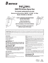
77-2915R-1
page 5 of 16
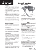
STARTUP AND OPERATION
(Part numbers referenced are contained
in the MX432 bare pump assemblies part
sheet: 77-2907-EU.)
GROUNDING THE BINKS PUMP
WARNING
To prevent static charging igniting the
flammable spray material, the BINKS
pump must be grounded before it is
started up. A grounding cable is
included with the pump.
!
1. Clamp the grounding cable to the
terminal on the high pressure filter or
the air motor.
2. Connect the other end of the grounding
cable to a suitable grounding device
(e.g. grounding bar).
PREPARING TO START UP THE
BINKS PUMP
Proceed as follows:
1. Check that the solvent cup
(0115-010059) is full to the
level shown. If necessary,
add material to the solvent
cup. (Order part no. 0114-009433 for
solvent based paint, and part no.
0114-014871 for waterborne paint.)
2. Select a suitable filter element using
the table in this manual (page 10) and
insert it into to the high pressure filter
(0115-010326).
3. Attach a suitable fluid hose to the
outlet fitting (0114-016059) on the
high pressure filter (0110-009130).
WARNING
The fluid hose supplied by BINKS is
identified with the maximum
permitted working pressure and the
bursting pressure. The lesser value—
the maximum permitted working
pressure—must be greater than the
maximum permitted working pressure
of the pump.
!
4. Connect the gun—designed at least
for the maximum permitted working
pressure of the pump— to the fluid hose.
5. Make sure that the ball valve on the air
control assembly is closed.
6. Connect the compressed air supply to
the air inlet connection.
7. The pump is equipped with an air
pressure regulator (0115-010183).
Before putting the pressure line
into operation, relieve the pressure
regulator by fully unscrewing the
regulating screw. Thereafter rotate
the regulating screw clockwise until
the pressure gauge (0115-010192) on
the regulator indicates the required
pressure.
NOTE
The pump is equipped with an air
pressure safety valve (0114-014774)
set at 8 bar (116 psi).
RINSING THE BINKS PUMP
WARNING
Wear eye protection.
!
Every BINKS pump is tested with water
during final inspection and thoroughly
rinsed with a non-gumming preservative
oil. With this rinsing process, it is
possible that the residual moisture of
water emulsion will be left in the pump.
Before the unit is started up for the first
time, a suitable solvent must be used to
thoroughly rinse out the remains of the
preservative fluid and the unavoidable
impurities introduced during equipment
assembly.
Proceed as follows:
1. Prepare the BINKS pump for start-up
as shown above.
2. Close the high pressure ball valve
(0114-019091) on the fluid filter.
3. Immerse the suction system in the tank
of solvent.
4. Insert the return flow hose (0114-
009103) into the tank of solvent.
Open the high pressure ball valve
(0114-019091) on the fluid filter.
5. Open the ball valve and set the
air regulator (0115-010183) to
approximately 1 bar (14.5 psi). The
suction system now draws in the
solvent. The solvent runs back to the
solvent tank through the high pressure
filter (0110-009130), the high pressure
ball valve (0114-019091) and the
return flow hose (0110-009103).
6. Remove the spray tip from the gun and
point the gun into the tank. Unlock
the safety lever on the gun, operate
the gun and close the high pressure
ball valve. The solvent will now flow
through the high pressure filter, the
fluid hose and the gun, back into the
tank. The time of rinsing depends on
the length of the material lines and
the solubility of the spray material.
We recommend a short reflush with
"fresh" solvent.
7. Release the gun trigger.
8. Slowly increase the pressure at the
regulator to maximum working
pressure while checking and testing
that all lines and screw and plug caps
are tightly sealed. If there are any
leaks in the system, shut down the
BINKS pump immediately. Only re-
start the BINKS pump once you have
repaired the leak.
9. Reduce the air pressure at the air
regulator (0115-010183) again and
close the ball valve.
10. Make sure that the return flow hose
(0110-009103) is still directed into
the solvent tank. Carefully open
the high pressure ball valve (0114-
019091) to reduce the pressure in the
fluid hose and in the high pressure
filter.
11. Point the gun into the tank of solvent
and operate the trigger, to reduce any
pressure which may still exist in the
fluid hose and in the gun.
CAUTION
If working with waterborne material,
the BINKS pump must again be
thoroughly rinsed with water before it
is started up.
!
START-UP
1. Prepare the BINKS pump for start-up
as shown above and if necessary, rinse
pump.
2. Close the high pressure ball valve
(0114-019091) on the fluid filter.
3. Immerse the suction system in the
spray material to be used.
4. Place the return flow hose (0110-
009103) in the tank. Then open the high
pressure ball valve (0114-019091).
5. Open the ball valve for the compressed
air supply and use the pressure
regulator (0115-010183) to set the
compressed air supply to 1 bar (14.5
psi). The pump will now draw in the
spray material. The spray material
flows back into the tank through the
high pressure filter, the high pressure
ball valve and the return pipe.
(continued on next page)