X-Rite D19C Standard > D19C Full Upgrade Datasheet
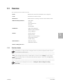
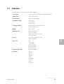
- Category
- Densitometers
- Type
- Datasheet


........................................................................................................................................
General
........................................................................................................................................
Function elements
........................................................................................................................................
Function selection
........................................................................................................................................
Densitometric functions
........................................................................................................................................
Settings
........................................................................................................................................
Device settings
........................................................................................................................................
Help
........................................................................................................................................
Maintenance
........................................................................................................................................
Options
........................................................................................................................................
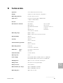
Technical data
........................................................................................................................................
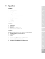
Appendices
1
2
3
4
5
6
7
8
9
10
11


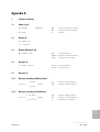
1 General
1.1 D19C and D196 densitometer
1.2 Documentation structure
1.3 User
1.4 Safety
1.4.1 Reference signs
1.4.2 Safety information
1.5 Packaging and transport
1
2
3
4
5
6
7
8
9
10
11

General
............................

General
............................
1
1.1
1.1 D19C and D196 densitometer
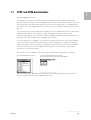
Dear GretagMacbeth customer,
Congratulations! You have just purchased a D19C or D190 densitometer. With its user-friendly
operation, high measuring accuracy and rugged design, this unit is a truly unique instrument. You can
therefore purchase the densitometer that will exactly meet your requirements. It’s modular design
also allows you to order additional functions which are not yet included in your D19C unit at any time
later on.
In the following, the operation instructions generally refer to the D190 densitometer. The designation
‘D190’ thereby stands for either ‘D19C’ or ‘D196’, depending on the type of unit you own.
The D19C and D196 units only differ in the number of available measuring functions. Otherwise, the
units are exactly identical and are also operated in the same way.
If a certain function is not available in your unit, then the respective menu lines will not be displayed
on your unit either. In this manual, all the functions which are available for a D190 are described in
detail. It is possible, therefore, that the description also includes functions which are not available in
your unit. However, if you order an additional function later on, you will find the corresponding
instructions in your present manual.
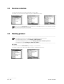
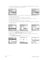
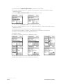
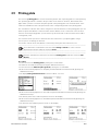
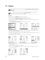
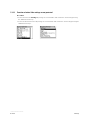
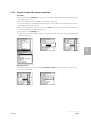
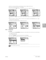
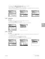
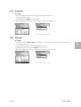
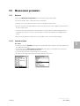
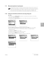
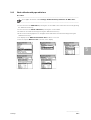
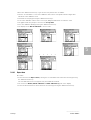
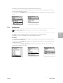
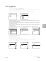
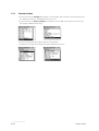
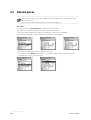
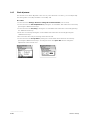
On your unit, the menu display of the function selection may be presented itself, for example,
like this (D196 densitometer) or like this (D19C densitometer with
the functions Density, Dot gain and Trapping)
Each individual function provided with your densitometer can be temporarily switched of. In this
case, the respective function will not appear in the menu.

General
............................
1.2 – 1.4.1
1.2 Documentation structure
This operating manual is divided into separate chapters to guide you step by step in the operation of
the D190 remission densitometer.
Most of the examples in this manual are based on the D196 or the equivalent D19C densitometer.
In the manual you find the description of all functions which can be available in the D19C, also those
which are not included in the D196.
To ensure the correct setting of the instrument and the proper measurement of the densitometric
functions, it is essential that the instructions are strictly observed.
1.3 User
With the conception of the D190 remission densitometer, particular attention has been paid to
user-friendly and easy operation. Prerequisite for proper operating is a formal training in the field of
printing or reprographic techniques or a specific personal introduction in the operation of the
remission densitometer.
1.4 Safety
For safe operation, the reading and understanding of the operating manual and the compliance with
the instructions is essential.
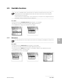
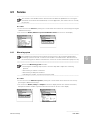
1.4.1 Reference signs
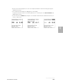
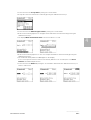
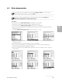
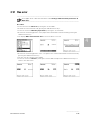
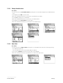
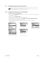
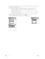
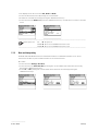
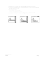
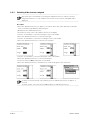
Important remarks in the operating manual are emphasized by the following three reference signs:
........................................................................................................................................
NOTE sign: Important operating references. Information which in case of non-observance may
lead to losses or troubles.
........................................................................................................................................
........................................................................................................................................
CAUTION sign: Information which in case of non-observance may result in material damage.
........................................................................................................................................
........................................................................................................................................
STOP-sign: Information which in case of non-observance may result in personal danger.
........................................................................................................................................

General
............................
1
1.4.2 – 1.5
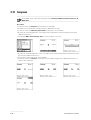
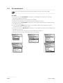
1.4.2 Safety information
........................................................................................................................................
The D190 remission densitometer is not intrinsically safe. It must therefore not be operated in
a hazardous environment.
........................................................................................................................................
........................................................................................................................................
The D190 remission densitometer must only be operated and maintained by trained persons
who are familiar with the instrument. The D190 remission densitometer must only be
operated under the specified operating conditions. Use only original GretagMacbeth
accessories and spare parts. Non-compliance with the safety information and instructions may
lead to incorrect measuring results and the loss of data as well as personal and material
damage.
........................................................................................................................................
........................................................................................................................................
Protect the GretagMacbeth calibration card from heat and direct sunlight, chemicals,
mechanical influences, etc. A defective calibration card may lead to an incorrect calibration and
therefore to incorrect measuring results. Always use the original shock-absorbing packaging to
transport the instrument. In addition, protect the instrument from strong electromagnetic
fields, open fire or sparks, chemicals, corrosive vapors, mechanical overloading and shock
effects. No emission of noise (silent).
........................................................................................................................................
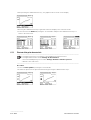
1.5 Packaging and transport
Every D190 remission densitometer leaves the factory packed in a cardboard box with shock-
absorbing inserts. Since this box gives the unit optimum protection against damage during transport,
please use it if you must return the unit to our factory or to one of our authorized representatives for
any reason.
........................................................................................................................................
Switching on and off the electronic safeguard; refer to chapter 2.6
........................................................................................................................................


1
2
3
4
5
6
7
8
9
10
11
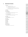
2 Function elements
2.1 Overview
2.2 Operating elements
2.2.1 Control ball
2.2.2 Measurement key
2.3 Display
2.4 Menu line symbols
2.5 Setting protection
2.6 Electronic safeguard
2.6.1 Switching on the electronic safeguard
2.6.2 Switching off the electronic safeguard
2.7 Charging the battery
2.7.1 Battery status indication
2.7.1.1 Display for partially discharged battery
2.7.1.2 Display for charged battery
2.7.1.3 Display for fully discharged battery
2.7.2 Charger
2.3.3 Charging procedure
2.8 Data protection


Function elements
............................
2
2.1
10 11
1
2
4
6
5
9
8
7
3
D19C
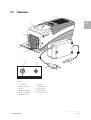
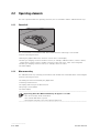
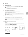
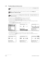
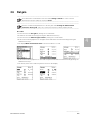
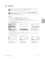
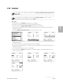
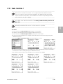
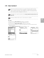
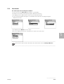
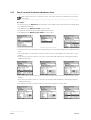
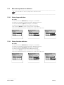
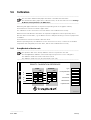
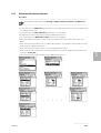
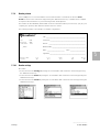
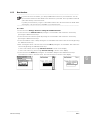
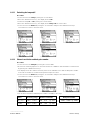
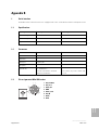
2.1 Overview
Legend
1 Control ball 7 Charger
2 Measurement key 8 Charger plug
3 Display 9 Power cable
4 Measuring module 10 Data interface
5 Measuring aperture 11 Charger socket
6 Calibration card

Function elements
............................
2.2 Operating elements
The unit is operated with two operating elements, the <Control ball> and the <Measurement key>.
2.2.1 Control ball
The <Control ball> is turned backwards and forwards with the index finger or the thumb.
It has the following functions:
• Moving the graphics bar for the selection of menu lines on the display.
• Entering or changing of numerical values such as, for example, calibration values, reference values,
target values, tolerance values, number of references per order, time, codes of the safeguard.
• Entering or changing of names such as, for example, names of orders.
• Activate display.
2.2.2 Measurement key
The <Measurement key> is briefly pressed down with the ball of the thumb and then released again.
It has the following functions:
• Activating the function marked by the graphics bar.
• Initiating a measurement.
• Accepting and storing of the data entered.
• Rejecting of entered data.
• Activate display.
........................................................................................................................................
By pressing down the <Measurement key> for approx. 3 seconds:
• the current activity will be terminated.
• the entered data will be rejected.
• the program will jump to the next higher program level.
........................................................................................................................................
2.2 – 2.2.2

Function elements
............................
2
2.3 – 2.4
l After pressing the <Measurement key>, the program jumps to the next lower menu level.
j After pressing the <Measurement key>, the program jumps to the next higher menu level.
!
After pressing the <Measurement key>, the next activity will be initiated.
After pressing the <Measurement key>, the entered data are accepted and stored.
After pressing the <Measurement key>, the entered data are rejected.
±
By turning the <Control ball>, the current value will be changed.
✓
Indicates the current status such as, for example, activated densitometric functions, current
filter selection (automatic or manual filter selection), current white base (paper white base or
absolute white base), current order, current reference, current printer, current handshake, etc.
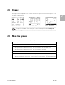
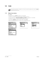
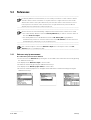
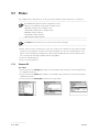
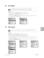
2.3 Display
The high-resolution display allows to show the results of a complete measurement sequence as well
as graphic representations.
........................................................................................................................................
To improve the readability of the display the contrast can be adjusted under Settings k
Device settings k LCD-contrast.
........................................................................................................................................
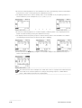
2.4 Menu line symbols
The menu line symbols have the following meaning:

Function elements
............................
2.5
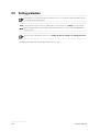
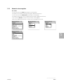
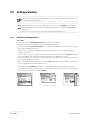
2.5 Setting protection
........................................................................................................................................
In the D19C you can activate a password protection of your settings (optional feature which is
not included in all instruments).
........................................................................................................................................
........................................................................................................................................
If the settings are protected, you will be able to select the menu ‘settings’ only by using a
password. Pleas don’t lose this password! Otherwise please contact your GretagMacbeth
service-center.
........................................................................................................................................
........................................................................................................................................
Switch on the setting protection refer to settings k device settings k setting protection.
........................................................................................................................................
For detailed description of the setting protection refer to 6.6.

Function elements
............................
2
2.6 – 2.6.1
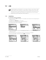
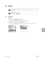
2.6 Electronic safeguard
........................................................................................................................................
The D190 remission densitometer is equipped with an electronic safeguard. It prevents the
measuring module from being extended if vibrations occur during transport.
........................................................................................................................................
........................................................................................................................................
The electronic safeguard can be switched on and off under Settings k Device settings k
Transport protection.
........................................................................................................................................
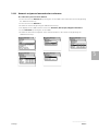
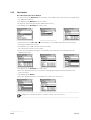
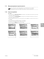
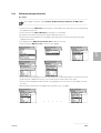
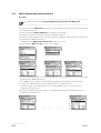
2.6.1 Switching on the electronic safeguard
Procedure:
• Select the menu line Settings by turning the <Control ball> and confirm the selection by pressing
the <Measurement key>.
• Select the menu line Device settings by turning the <Control ball> and confirm the selection by
pressing the <Measurement key>.
• Select the menu line Transport protection by turning the <Control ball>.
• Switch on the electronic safeguard by pressing the <Measurement key>.
• The display shows a code number for the release of the electronic safeguard.

Function elements
............................
2.6.2
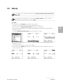
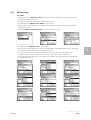
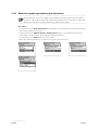
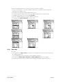
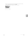
2.6.2 Switching off the electronic safeguard
........................................................................................................................................
After turning the <Control ball> or after actuating the <Measurement key> with the electronic
safeguard switched on, a code number for the release of the electronic safeguard will be
displayed.
........................................................................................................................................
Procedure:
• Press the <Measurement key> for approx. 3 seconds to delete any entries that may accidentally
have occurred through vibrations during transport.
• Briefly press the <Measurement key>.
• A field for the entry of the code number appears on the display.
• Use the <Control ball> to select the first figure of the code number.
• Press the <Measurement key> to enter the first figure.
• Use the <Control ball> to select the second figure of the code number.
• Press the <Measurement key> to enter the second figure.
• Use the <Control ball> to select the third figure of the code number.
• Press the <Measurement key> to enter the third figure.
• Select the entry line OK by turning the <Control ball>.
• Press the <Measurement key> repeatedly to return the program to the main menu.
........................................................................................................................................
To delete incorrectly entered code numbers, press the <Measurement key> for approx. 3
seconds. To delete a figure, select the entry line
o and press the <Measurement key>.
........................................................................................................................................

Function elements
............................
2
2.7 – 2.7.1.2
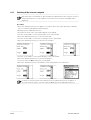
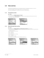
2.7 Charging the battery
........................................................................................................................................
Battery type refer to Settings k Device Settings k Battery.
........................................................................................................................................
2.7.1 Battery status indication
........................................................................................................................................
The battery status is permanently indicated on the display. If the battery is discharged, the unit
will display a message and must then be recharged.
........................................................................................................................................
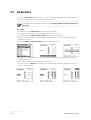
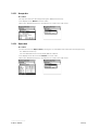
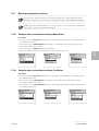
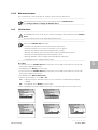
2.7.1.1 Display for partially discharged battery
........................................................................................................................................
Whenever the display of the D190 indicates that the battery is partially discharged, it is
advisable to connect the unit to the charger again until the battery is completely recharged.
........................................................................................................................................
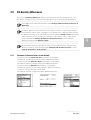
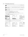
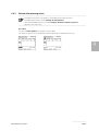
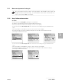
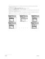
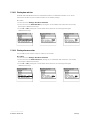
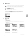
The display of the D190 indicates a partially discharged battery as follows:
The symbol of an empty battery at the top or bottom right of the display indicates that the capacity
has been reduced to only a few hundred measurements and that the charger should occasionally be
connected to the D190.
2.7.1.2 Display for charged battery
........................................................................................................................................
If the battery is charged, we recommend to operate the unit without the charger until the
display indicates that the battery is partially discharged.
........................................................................................................................................
The display of the D190 indicates a charged battery as follows:
The symbol of an empty battery is not displayed as long as the battery is fully charged.

Function elements
............................
2.7.1.3 – 2.8
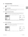
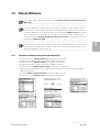
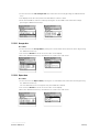
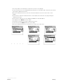
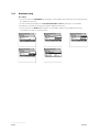
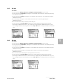
2.7.1.3 Display for fully discharged battery
........................................................................................................................................
If the battery is discharged, the unit will display the message ‘battery empty’ and must then be
recharged.
........................................................................................................................................
2.7.2 Charger
........................................................................................................................................
Use only original GretagMacbeth accessories and spare parts; see chapter 9 Options.
........................................................................................................................................
........................................................................................................................................
Make sure that the voltage indicated on the charger corresponds with the local line voltage. If
this is not the case, contact your nearest GretagMacbeth representative to have the charger
switched over or exchanged. Chargers must only be opened and switched over by qualified
specialists.
........................................................................................................................................
2.7.3 Charging procedure
........................................................................................................................................
Before the D190 remission densitometer is used for the first time, it must be charged with the
supplied charger. A fully charged battery allows for approx. 4000 measurements.
........................................................................................................................................
Procedure:
• Connect the charger to the power supply via the power cable.
• Connect the charger to the D190 remission densitometer via the charger cable.
• Charge the battery for approx. 3 hours.
• Remove the charger cable and disconnect the charger from the power supply.
........................................................................................................................................
The rapid charge of the battery results in a noticeable temperature increase in the housing.
This temperature increase is not of importance and will disappear when the battery is fully
charged.
........................................................................................................................................
2.8 Data protection
The data storage is backed up by a buffer battery with a service life of about 10 years. This prevents
a loss of data even if the rechargeable battery is not installed.
Page is loading ...
Page is loading ...
Page is loading ...
Page is loading ...
Page is loading ...
Page is loading ...
Page is loading ...
Page is loading ...
Page is loading ...
Page is loading ...
Page is loading ...
Page is loading ...
Page is loading ...
Page is loading ...
Page is loading ...
Page is loading ...
Page is loading ...
Page is loading ...
Page is loading ...
Page is loading ...
Page is loading ...
Page is loading ...
Page is loading ...
Page is loading ...
Page is loading ...
Page is loading ...
Page is loading ...
Page is loading ...
Page is loading ...
Page is loading ...
Page is loading ...
Page is loading ...
Page is loading ...
Page is loading ...
Page is loading ...
Page is loading ...
Page is loading ...
Page is loading ...
Page is loading ...
Page is loading ...
Page is loading ...
Page is loading ...
Page is loading ...
Page is loading ...
Page is loading ...
Page is loading ...
Page is loading ...
Page is loading ...
Page is loading ...
Page is loading ...
Page is loading ...
Page is loading ...
Page is loading ...
Page is loading ...
Page is loading ...
Page is loading ...
Page is loading ...
Page is loading ...
Page is loading ...
Page is loading ...
Page is loading ...
Page is loading ...
Page is loading ...
Page is loading ...
Page is loading ...
Page is loading ...
Page is loading ...
Page is loading ...
Page is loading ...
Page is loading ...
Page is loading ...
Page is loading ...
Page is loading ...
Page is loading ...
Page is loading ...
Page is loading ...
Page is loading ...
Page is loading ...
Page is loading ...
Page is loading ...
Page is loading ...
Page is loading ...
Page is loading ...
Page is loading ...
Page is loading ...
Page is loading ...
Page is loading ...
Page is loading ...
Page is loading ...
Page is loading ...
Page is loading ...
Page is loading ...
Page is loading ...
Page is loading ...
Page is loading ...
Page is loading ...
Page is loading ...
Page is loading ...
Page is loading ...
Page is loading ...
Page is loading ...
Page is loading ...
Page is loading ...
Page is loading ...
Page is loading ...
Page is loading ...
Page is loading ...
Page is loading ...
Page is loading ...
Page is loading ...
Page is loading ...
Page is loading ...
Page is loading ...
Page is loading ...
Page is loading ...
Page is loading ...
Page is loading ...
Page is loading ...
Page is loading ...
Page is loading ...
Page is loading ...
Page is loading ...
Page is loading ...
Page is loading ...
Page is loading ...
Page is loading ...
Page is loading ...
Page is loading ...
Page is loading ...
Page is loading ...
Page is loading ...
Page is loading ...
Page is loading ...
Page is loading ...
Page is loading ...
Page is loading ...
Page is loading ...
Page is loading ...
Page is loading ...
Page is loading ...
Page is loading ...
Page is loading ...
Page is loading ...
Page is loading ...
-
 1
1
-
 2
2
-
 3
3
-
 4
4
-
 5
5
-
 6
6
-
 7
7
-
 8
8
-
 9
9
-
 10
10
-
 11
11
-
 12
12
-
 13
13
-
 14
14
-
 15
15
-
 16
16
-
 17
17
-
 18
18
-
 19
19
-
 20
20
-
 21
21
-
 22
22
-
 23
23
-
 24
24
-
 25
25
-
 26
26
-
 27
27
-
 28
28
-
 29
29
-
 30
30
-
 31
31
-
 32
32
-
 33
33
-
 34
34
-
 35
35
-
 36
36
-
 37
37
-
 38
38
-
 39
39
-
 40
40
-
 41
41
-
 42
42
-
 43
43
-
 44
44
-
 45
45
-
 46
46
-
 47
47
-
 48
48
-
 49
49
-
 50
50
-
 51
51
-
 52
52
-
 53
53
-
 54
54
-
 55
55
-
 56
56
-
 57
57
-
 58
58
-
 59
59
-
 60
60
-
 61
61
-
 62
62
-
 63
63
-
 64
64
-
 65
65
-
 66
66
-
 67
67
-
 68
68
-
 69
69
-
 70
70
-
 71
71
-
 72
72
-
 73
73
-
 74
74
-
 75
75
-
 76
76
-
 77
77
-
 78
78
-
 79
79
-
 80
80
-
 81
81
-
 82
82
-
 83
83
-
 84
84
-
 85
85
-
 86
86
-
 87
87
-
 88
88
-
 89
89
-
 90
90
-
 91
91
-
 92
92
-
 93
93
-
 94
94
-
 95
95
-
 96
96
-
 97
97
-
 98
98
-
 99
99
-
 100
100
-
 101
101
-
 102
102
-
 103
103
-
 104
104
-
 105
105
-
 106
106
-
 107
107
-
 108
108
-
 109
109
-
 110
110
-
 111
111
-
 112
112
-
 113
113
-
 114
114
-
 115
115
-
 116
116
-
 117
117
-
 118
118
-
 119
119
-
 120
120
-
 121
121
-
 122
122
-
 123
123
-
 124
124
-
 125
125
-
 126
126
-
 127
127
-
 128
128
-
 129
129
-
 130
130
-
 131
131
-
 132
132
-
 133
133
-
 134
134
-
 135
135
-
 136
136
-
 137
137
-
 138
138
-
 139
139
-
 140
140
-
 141
141
-
 142
142
-
 143
143
-
 144
144
-
 145
145
-
 146
146
-
 147
147
-
 148
148
-
 149
149
-
 150
150
-
 151
151
-
 152
152
-
 153
153
-
 154
154
-
 155
155
-
 156
156
-
 157
157
-
 158
158
-
 159
159
-
 160
160
-
 161
161
-
 162
162
-
 163
163
-
 164
164


X-Rite D19C Standard > D19C Full Upgrade Datasheet
- Category
- Densitometers
- Type
- Datasheet
Ask a question and I''ll find the answer in the document
Finding information in a document is now easier with AI
Related papers
-
X-Rite B/W Reflection Densitometer 400 User manual
-
-
Xerox DTP32HS User guide
-
X-Rite IntelliTrax D65 Datasheet
-
-
-
-
X-Rite CQ5O-6O-50L-U Operating instructions
-
Other documents
-
 Heiland electronic TRD 2 User manual
-
 BIO RAD gs-800 User manual
-
Kodak Printer 6B6640 User manual
-
-
Sharp AR-C360P Owner's manual
-
-
Toshiba GA-1121 User manual
-
Grant Instruments DEN-1 and DEN-1B densitometers User manual
-
Xerox DocuColor 30 PRO User guide
-

