Extron DTP T EU 232 User manual

Category
Video switches
Type
User manual

This manual is also suitable for

1
IMPORTANT:
Go to www.extron.com for the complete
user guide, installation instructions, and
specifications bef
ore connecting the
pr
oduct to the po
wer source.
Rear and Side
(Make connections before installation)
Front
(Make connections after installation)
A
TP function switch
B
Conguration (USB)
C
DTP output
D
RS-232/IR Over TP output
E
Remote RS-232
F
DC power input
G
Reset button
H
HDMI input
I
VGA Input
J
Audio input
K
LEDs
Figure 2. DTP T EU Unit Installation Diagram
Figure 3. DTP T MK Unit Installation Diagram
Wall Box
Mounting Plate
Install the
mounting
plate.
Mount the
device.
4
2
Install the
mounting
plate.
Wall Box
Mounting Plate
Mount the
device.
4
2
DTP T EU and DTP T MK • Setup Guide
This guide provides instructions for an experienced installer to install any of the Extron
DTP T EU 332, DTP T EU 232, DTP T MK 332, or DTP T MK 232 switching transmitters into an EU or
MK two-gang junction box or European cable channel system and to make all connections.
The transmitters switch between one analog video and one digital (HDMI) video input and, paired with a compatible receiver, can extend
the selected signal up to 330 feet (100 m) (DTP T EU 332 and DTP T MK 332) or 230 feet (70 m) (DTP T EU 232 or DTP T MK 232).
Side FrontRear
DTP
HDBT
RESET
CONFIG
1.0 A MAX
SIGLINK
OUT
Tx Rx GTxRxGTx Rx
RS-232
OVER TP
RS-232
POWER
12V
IR
REMOTE
HDMI IN
PWR HDCP HDMI VGA AUTO
VGA IN
DTP T EU 332
AUDIO IN AUDIO IN
B
A
C
G
F
ED IJ K JH
Figure 1. DTP T EU and DTP T MK Unit Features
(DTP T EU 332 Shown)
Installation
Planning
CAUTION: Failure to check these items may result in personal injury or
property damage.
ATTENTION : La non-vérication des éléments listés ci-dessous peut
provoquer des blessures ou dommages matériels.
Check that the installation meets the building, electrical, and safety codes.
Ensure there is enough space in the junction box or Euro channel for the DTP
transmitter, cables, and rear panel connectors when the DTP transmitter is
completely connected and mounted.
NOTE: The transmitters require 36 mm (1.4 inch) minimum depth.
Mounting and Cabling
For additional mounting details and considerations, see the DTP T EU 332,
DTP T MK 332, DTP T EU 232, and DTP T MK 232 User Guide at www.extron.com).
Step 1 — Install the junction box or Euro channel
Install the appropriate junction box or Euro channel according to the requirements
of the manufacturer (refer to the manufacturer for more details). This may require
creating an opening in the mounting surface. If so, consider the following:
For accuracy, use a template or the mounting enclosure to mark cut
guidelines.
To avoid making an opening too big, cut inside the marked guidelines.
Step 2 — Install the mounting plate
For the DTP T EU units, use four long mounting screws to attach the mounting
plate to the junction box (see gure 2,
2
).
For the DTP T MK units, use two long mounting screws to attach the mounting
plate to the junction box (see gure 3,
2
).
NOTE: For installation into a Euro channel, refer to the manufacturer of the
Euro channel for any additional installation requirements.
2
DTP T EU and DTP T MK • Setup Guide (Continued)
Step 3 — Set the TP function switch and make rear and side panel connections (see figure 1 for numbers)
A
TP function switch
If the receiving device is in the Extron DTP series, set this switch to DTP. The TP output consists of HDMI with embedded audio,
analog audio, RS-232 and IR, and remote power. The transmitter and receiver can be powered by one 12 VDC power supply
connected to either unit.
For an HDBaseT-enabled receiver, set this switch to HDBT position. The TP output consists of HDMI with embedded audio plus
RS-232 and IR. The transmitter and receiver each requires its own 12 VDC power supply.
ATTENTION:
Position this switch BEFORE connecting the appropriate device to the TP connector. Failure to comply can damage the
endpoint.
Positionnez le sélecteur AVANT de connecter l’appareil approprié au connecteur TP. Ne pas respecter cette procédure
pourrait endommager le point de connexion.
B
Configuration port — Plug a PC or other controlling device into the switching transmitter via this mini-USB connector for remote
conguration of the switching transmitter.
C
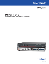
Out port— Connect the Out (RJ-45) port to the DTP In port on the receiver. Extron recommends that you
terminate both cable ends in accordance with the following, at a minimum: TIA/EIA T 568B and 24 AWG,
solid conductor, shielded cable with 400 MHz bandwidth.
ATTENTION:
Do not connect this connector to a computer data or telecommunications network.
Ne connectez pas ces port à des données informatiques ou à un réseau de télécommunications.
Signal LED indicator — Lights when the device is transmitting a video signal or a test pattern.
Link LED indicator — Lights when a valid link between a DTP or HDBT input and output is established.
D
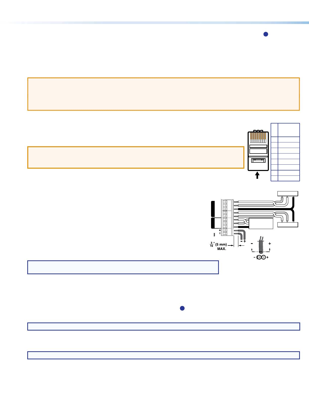
Over TP connector — To pass serial and infrared data or control signals on the Over
TP RJ-45 output, connect the controlling device to the transmitter via the RS-232 and
IR captive screw connector as shown at right. Connect the devices to be controlled to
the receiver.
E
Remote RS-232 port — For serial RS-232 control, connect a host device or control
system to the 3.5 mm, 3-pole captive screw connector. The wiring and protocol are
shown at right.
F
Power — Connect the included 12 VDC power supply to either unit, transmitter or
receiver, as shown at right. Use the included tie-wrap to strap the cord to the captive
screw connector.
Connect an IEC power cord between the power supply and a 100-240 VAC, 50-60 Hz
source.
NOTE: If the TP switch (
A
) is in DTP, one power supply can power both units.
If the switch is in HDBT, each unit requires its own power supply.
Step 4 — Mount the device
Using the provided screws, attach the device to the four mounting anges on the mounting plate (see gure 2 or gure 3 on the
previous page..
Step 5 — Make front panel (input) connections (see figure 1 for numbers)
H
HDMI input port — Connect an HDMI cable between this port and the HDMI output port of the digital video source.
NOTE: See LockIt
®
Lacing Brackets on the next page to securely fasten the HDMI connector to the transmitter.
I
VGA Input port — Connect a VGA cable between this port and the VGA output port of the analog video source.
J
Audio input — Connect an unbalanced stereo audio source to this 3.5 mm mini stereo jack for an analog audio input.
NOTE: Analog input audio is not embedded in the HDMI signal; it is transmitted separately and is present for any selected input.
5
Pin
1
2
3
6
7
8
4
Wire color
White-green
Green
White-orange
White-blue
Orange
White-brown
Brown
Blue
TIA/EIA T
568B
TP Wires
12345678
Pins:
RxTx
TxRx
Gnd
Gnd
IR Device
RS-232 De
vice
Control Device
Tx
Rx
Gnd
9600 Baud
8 data bits
No parity
1 stop bit
1.0 A MAX
Tx Rx GTxRxGTx Rx
RS-232
OVER TP
RS-232
POWER
12V
IR
REMOTE
SECTION
A–A
Ridges
Smooth
AA
3
Operation
After all connected devices are connected and powered on, the system is fully operational. If any issues arise, verify that the cables
are routed and connected properly. The switching transmitter can be congured and controlled using Extron Simple Instruction Set
(SIS) commands and Product Conguration Software (see the DTP T EU 332, DTP T MK 332, DTP T EU 232, and DTP T MK 232 User
Guide at www.extron.com).
Indicators (
K
, see figure 1)
PWR HDCP HDMI VGAAUTO
Power LED Lights when power is applied.
HDCP LED Lights when the HDMI input signal is encrypted.
HDMI LED Lights when the HDMI input signal is detected.
VGA LED Lights when the VGA input signal is detected.
Auto LED Lights when device is in auto switch mode. Auto switch is on by default.
When auto switch is on, the switcher automatically selects the input, HDMI or VGA, that has a valid signal present. When signals are
present on both inputs. the switcher selects VGA.
NOTE: Auto switch mode can be toggled off and on using the SIS commands. Issue the EnAUSW} SIS command,
where n = 0 (off) or 1 (on). The switcher responds with Auswn]. See the DTP T EU 332, DTP T MK 332, DTP T EU 232, and
DTP T MK 232 User Guide at www.extron.com, for details.
Rest button (
G
, see figure 1)
This recessed button initiates two levels of reset. See the DTP T EU 332, DTP T MK 332, DTP T EU 232, and DTP T MK 232 User
Guide at www.extron.com, for details.
LockIt
®
Lacing Brackets
Use the included LockIt Lacing Brackets to securely fasten the HDMI cable as follows.
1. Plug the HDMI cable into the panel connection.
HDMI IN
1
2
3
444
555
2. Loosen the HDMI connection mounting screw from the panel enough to allow
the LockIt lacing bracket to be placed over it. The screw does not have to be
removed.
3. Place the LockIt lacing bracket on the screw and against the HDMI connector,
then tighten the screw to secure the bracket.
ATTENTION:
Do not overtighten the HDMI connector mounting screw. The shield it
fastens to is very thin and can easily be stripped.
Ne serrez pas trop la vis de montage du connecteur HDMI. Le blindage
auquel elle est attachée est très n et peut facilement être dénudé.
4. Loosely place the included tie wrap around the HDMI connector and the LockIt
lacing bracket as shown.
5. While holding the connector securely against the lacing bracket, use pliers or
similar tools to tighten the tie wrap, then remove any excess length.
4
68-2713-50 Rev. A
09 14
Extron Headquarters
+800.633.9876 Inside USA/Canada Only
Extron USA - West Extron USA - East
+1.714.491.1500 +1.919.850.1000
+1.714.491.1517 FAX +1.919.850.1001 FAX
Extron Europe
+800.3987.6673
Inside Europe Only
+31.33.453.4040
+31.33.453.4050 FAX
Extron Asia
+65.6383.4400
+65.6383.4664 FAX
Extron Japan
+81.3.3511.7655
+81.3.3511.7656 FAX
Extron China
+86.21.3760.1568
+86.21.3760.1566 FAX
Extron Middle East
+971.4.299.1800
+971.4.299.1880 FAX
Extron Korea
+82.2.3444.1571
+82.2.3444.1575 FAX
Extron India
1800.3070.3777
(Inside India Only)
+91.80.3055.3777
+91.80.3055.3737 FAX
© 2014 Extron Electronics All rights reserved. All trademarks mentioned are the property of their respective owners. www.extron.com
DTP T EU and DTP T MK • Setup Guide (Continued)
POWER
12V
2
--A MAX
Rx GTx RxTxG
RS-232 IR
RxTx
1
RGB, Y, R-Y, B-Y HDMI HDMI
SIG LINK
DTP OUT
AUDIO
CONTACTRS-232TALLY
3
123G 123+V
RESET
INPUTS
OVER DTPREMOTE
50-60 Hz
100-240V ~
2.0 A MAX
1
L
R
SIG LINK
OUT
SIG LINK
OUT
1
3
4
4
XTP
RS-232 IR
Tx Rx
RTSCTS
GTxRxG Tx Rx G
RS-232 IR
Tx Rx Tx RxG
Tx Rx G
Tx Rx Tx Rx
XTP
RESET
S/PDIF
OUT
DTP
XTP
DTP
XTP
DTP
EXP
+48V
MIC/LINE
1
1
3
2
4
2
3
4
LINK
LAN 2
LAN 1
LAN 3
HDBT
G
DTP
HDBT
2
1234
5
7
8
6
DTP CROSSPOINT 84
4
CLASS 2 WIRING
8/
R
RS-232 IR
Tx Rx Tx RxG
OVER TP
OVER TP
REMOTE
SIG LINK
IN
SIG LINK
IN
AUDIO INPUTS
AUDIO OUTPUTS
AMP OUTPUT
CONTROL
1234G
DIGITAL I/OCOM 3COM 2COM 1
S
DMP EXPANSION
SGG
1
1
2
2
C34C
INPUTS
-S G+S+V
PWR OUT = 6W
OUTPUTS
RS-232 IR
Tx Rx Tx RxG
1
LR
1
LR
3
LR
3
LR
5
LR
2
LR
4
LR
2
LR
4
LR
6
LR
IR/SERIAL eBUSRELAYS
LR
POWER
12V
0.7A MAX
AUDIO
SIG LINK
DTP IN
OUTPUTS
LR
POWER
12V
0.7A MAX
AUDIO
SIG LINK
DTP IN
OUTPUTS
DTP HDMI 330 Rx
OVER DTP
RS-232
IR
Tx Rx Tx RxG
DTP HDMI 230 Rx
OVER DTP
RS-232
IR
Tx Rx Tx RxG
Extron Extron
Help
System
Off
Display
Room
Control
Off
Mute
Screen
Lighting
December 15, 2013 - 7:58 AM
Audio
Control
Volume
Mute
Tuner
1 2 3
VCRLaptop PC DVD
Doc
Cam
Tuner
On
Channel
Last
Presets
More
Presets
321
654
987
Enter
0
HDMI IN
PWRHDCPHDMI VGA AUTO
VGA IN
DTP T EU 332
AUDIO IN AUDIO IN
HDMI IN
PWRHDCP HDMI VGA AUTO
VGA IN
DTP T EU 332
AUDIO IN AUDIO IN
Extron
DTP T EU 332
Two Input DTP Transmitter
for EU-type Junction Boxes
Display
Extron
DTP HDMI
330 Rx
Receiver
RS-232 HDMI
Display
RS-232 HDMI
CATx Cable
up to 330'
(100 m)
CATx Cable
up to 330'
(100 m)
CATx Cable
up to 230'
(70 m)
CATx Cable
up to 330'
(100 m)
Extron
DTP HDMI
230 Rx
Receiver
Ethernet
Ethernet
AudioAudio
Extron
DTP T USW 333
Transmitter
Inputs
Outputs
AV
Control
Network
Microphones
Extron
DTP CrossPoint 84 IPCP SA
Scaling Presentation Matrix Switcher
with DTP Extension and Control Processor
Extron
SM 26
Surface Mount
Speakers
Extron
TLP Pro 1020T
10" Tabletop TouchLink
Pro Touchpanel
  • Page 1 1
  • Page 2 2
  • Page 3 3
  • Page 4 4

Extron DTP T EU 232 User manual

Category
Video switches
Type
User manual
This manual is also suitable for

Ask a question and I''ll find the answer in the document

Finding information in a document is now easier with AI