ADDER AdderLink AV200 series Owner's manual

Category
PC/workstation barebones
Type
Owner's manual
AdderLink AV200 series
Digital Signage Extenders

ADDER
®
TRANSMITTER
LINK 5 LINK 6 LINK 7 LINK 8
LINK 1
POWER
LINK 2 LINK 3 LINK 4
ADDERLINK
www.adder.com
208
OUT
OUT
OUT
OUT
OUT
IN
 


1

SECT 1
Contents
Welcome
Introduction .................................................................................2
Standard AdderLink AV200 models .......................................2
Support for DDC (Display Data Channel) ..............................3
Expansion via cascade links ....................................................4
What’s in the box ........................................................................5
What you may additionally need ...............................................5
Module features ..........................................................................6
Installation
Locations ......................................................................................7
Mounting .....................................................................................8
Using the self adhesive feet ...................................................8
Using the rear mounting slot ................................................. 8
Using the optional rack mount chassis ..................................9
Making standard connections ..................................................10
Connections at the transmitter ............................................ 10
Connections at the receiver .................................................15
Making cascade connections ....................................................17
Important limitations when cascading ................................17
Cascade connection example ...............................................17
Cascading transmitters .........................................................18
Switch settings - AV204T/AV208T only .....................................19
Operation
Indicators....................................................................................20
Serial port switching..................................................................21
Adjustments ...............................................................................22
Brightness and sharpness adjustments ................................ 22
Skew compensation adjustments (AV201R only) ................23
Upgrading .............................................................................25
Further information
Troubleshooting ........................................................................26
Getting assistance ......................................................................26
Safety information ....................................................................27
Warranty ....................................................................................27
Products in the AdderLink AV200 range ..................................28
Cables .........................................................................................28
Y-cable pinout .......................................................................28
Emissions and Immunity ............................................................29
 


2

SECT 2
Welcome
Introduction
The AdderLink AV200 family of digital signage extenders provide a modular
method to distribute high quality video and audio to remote display units as well
as handling serial control signals. The various modules of the AdderLink AV200
family support a wide range of configurations: from individual point-to-point
installations to multiple screen distributions, all via CATx cabling at distances up
to 300m (1000 feet).
All AdderLink AV200 modules provide full support for RS232 serial
communications between the host system and the display(s). This support
extends not just to point-to-point connections, but also to larger scale
installations using AV204 and AV208 transmitters. The inclusive Adder Display
Manager utility provides the final piece of the puzzle and allows remote, flexible
control of all devices attached to the AdderLink AV installation.
Standard AdderLink AV200 models
There are three styles of AdderLink AV200 transmitters and two types of receiver
modules available. The choice of each depends upon the quantity of devices that
need to be supported and the layout of each installation as a whole:
AdderLink AV200P point-to-point
The AdderLink AV200P transmitter and receiver provide point to point operation
capable of directly supporting dual displays and speaker sets. The transmitter
can additionally support a local monitor and speaker set located adjacent to the
source system. At the receiver a single RS232 serial connector is available for
linking to a single display (AV200R receivers can support dual serial ports via a
special Y-cable but only when linked to AV204T or AV208T transmitters).
VIDEO
CATx LINK
UP TO 300m
AUDIO
RS232 SERIAL
POWER POWER
PC
TRANSMITTER RECEIVER
200R200T
AdderLink AV200 transmitter and receiver pair driving two remote
displays (with serial control to one of them) and speakers in
addition to a local monitor and speaker set
The AV200P transmitter and receiver modules are also available separately and
are known as the AV200T and AV200R respectively. Expansion is made possible
by connecting further transmitters to the original AV200T transmitter module,
however, the serial connection cannot be cascaded in this manner. Where
cascades with serial connections (as well as video and audio) are required, use
the AV204T/AV208T transmitters.
AdderLink AV201R
An AV201R receiver is also available which provides all of the functionality of the
AV200R with the addition of special skew adjustments to correct cable-induced
video timing errors on long CATx connections.
RECEIVER
200R
TRANSMITTER
200T
RECEIVER
201R
TRANSMITTER
204T
TRANSMITTER
208T
Transmitters
Receivers
AV200T
Can directly drive a
single receiver module
AV204T
Can directly drive
up to four receiver
modules
AV208T
Can directly drive
up to eight receiver
modules
AV200R
Supports two displays
and speaker sets
AV201R
Supports two displays
and speaker sets. Also
includes video skew
adjustment controls.
Module mixing - IMPORTANT
When necessary, the AV204T and AV208T modules can be used to link with
AV100 receivers, however, the serial communications facilities must be first
disabled using switch 10 on the AV204T/AV208T modules (see Switch settings
for details)
 


3

CATx LINK UP TO 300m
SERIAL
Y-CABLE
POWER
RECEIVER
200R
RECEIVER
200R
VIDEO
AUDIO
POWER
PC
RS232 SERIAL
TRANSMITTER
204T/208T
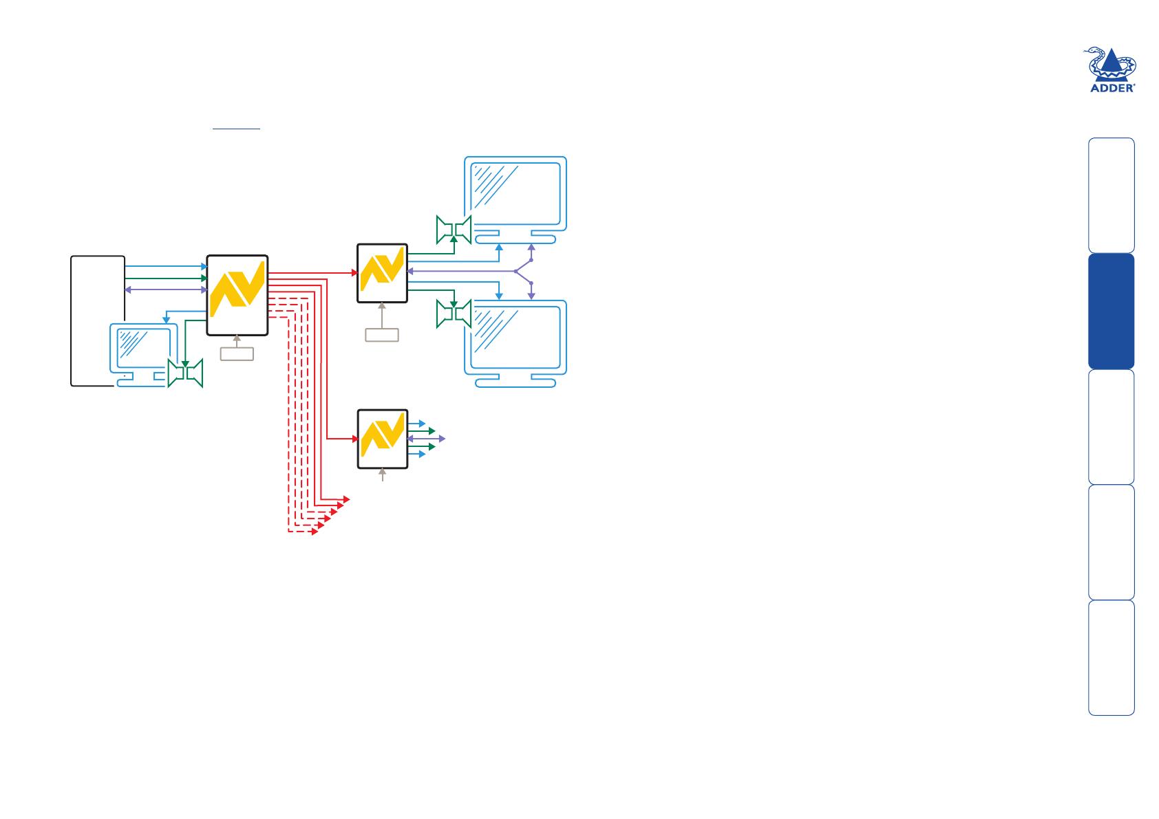
AdderLink AV204T and AV208T transmitters
The AdderLink AV204T transmitter provides four CATx outputs while the AV208T
provides eight CATx output to directly drive AV200R/AV201R receiver modules
located at distances up to 300m (1000 feet).
Note: An optional serial Y-cable is available (part number: VSC19), which allows a
connected receiver to provide a serial link to each display.
AdderLink AV204T/AV208T transmitter driving
up to four/eight remote receivers, in addition
to a local monitor and speaker set
Additional expansion is also possible by connecting further transmitter modules to
the original module in a cascade arrangement, each supporting their own multiple
AV200R/AV201R receiver modules - See Expansion via cascade links for details.
Support for DDC (Display Data Channel)
The Display Data Channel standard allows video monitors to define
their characteristics so that the source computers to which they are
connected can optimise their video outputs accordingly. By their nature,
the AdderLink AV extenders enable multiple video displays to be attached
to a single source computer. This causes a complication for handling the
DDC standard, however, in characteristic style we have devised an elegant
solution, as detailed below.
Whenever an AdderLink AV transmitter is powered on, it checks its local
video port for a working display monitor with DDC information. The
following strictly ordered actions occur to automatically locate the most
suitable DDC data:
• Ifadisplaymonitorisdiscoveredonthelocalvideoportofthe
transmitter, the DDC data are cloned from it and stored within the
transmitter.
• Ifnodisplaymonitorisdiscoveredonthelocalvideoportofthe
transmitter, the DDC data held within the transmitter will remain
unchanged.
• IftheDDCdataorclocklinesofthetransmitter’slocalvideoportare
discovered to be connected to ground, then a default set of DDC data
will be reloaded and used.
After the initial search period, the stored DDC data are then presented to
the video port of the source computer. When transmitters are cascaded,
only the primary transmitter (the one connected to the source computer)
will perform the search for DDC data.
AdderLink AV transmitters hold two pages of DDC data in order to
support the most advanced display monitors. The DDC data are held
within non-volatile memory so that they are retained when power is
removed.
Themannerinwhichthetransmitterssearchforsuitable‘DDCdonors’
could have an impact if your installation contains display units with
differing capabilities. Generally, you should arrange for the display
monitor with the most representative capabilities of your whole
installation to be the one that the transmitter locates on its local port,
either initially (and temporarily) while commissioning or permanently.
 


4

Expansion via cascade links
Inordertocreatesmall,mediumandlargedigitalsignagenetworks,allAV200
transmitters are designed to support additional transmitter modules (and their
subsequent multiple receivers). This is achieved using the video, audio and serial
out ports to provide the inputs into the next transmitter module, and so on.
AV transmitters can be
connected in cascade to
provide further video,
audio and serial expansion
opportunities. Note that
the AV200T transmitter
does not support serial
cascade connections.
CASCADE LINK
CASCADE LINK
CATx LINKS TO RECEIVERS
CASCADE LINK
CASCADE LINK
CASCADE LINK
CASCADE LINK
VIDEO
AUDIO
POWER
POWER
PC
Primary
Transmitter
RS232 SERIAL
TRANSMITTER
TRANSMITTER
204T/208T
204T/208T
Note: The AV200T transmitter supports video and audio cascade connections,
however, the module does not include a serial out connector and cannot
support cascaded serial connections.
A limit of three cascade connections are possible between transmitter modules.
Using the corresponding maximum of four AV208T transmitters, this gives an
overall support for up to 64 remote displays on 32 separate CATx branches.
 


5

ADDER
®
TRANSMITTER
LINK 5 LINK 6 LINK 7 LINK 8
LINK 1
POWER
LINK 2 LINK 3 LINK 4
ADDERLINK
www.adder.com
208
OUT
OUT
OUT
OUT
OUT
IN
For each AV module:
5.3V Power adapter and
country-specific mains cable
Self adhesive
rubber feet
Video cable to connect a
transmitter to the source PC
and optionally to connect
additional transmitter
modules in cascade.
Adder P/N: VSC18
RECEIVER
200
ADDERLINK
OUT
OUT
TRANSMITTER
200
ADDERLINK
IN
IN
Whats in the box What you may additionally need
AdderLink AV200T transmitter
and/or AV200R/AV201R
receiver. AV200T and AV200R
modules can be supplied as a
pair under the code AV200P
Stereo audio cable to
connect a transmitter to the
source PC and optionally
to connect additional
transmitter modules in
cascade.
Adder P/N: VSC22
CD-ROM containing
skew test pattern
and documentation
For part numbers of other items, please also refer to the
section Products in the AdderLink AV range.
Rack mount fascia plates for modules:
For AV200T/AV200R/AV201R
Adder P/N: ALAV-RMK-FASCIA
For AV204T/AV208T
Adder P/N: ALAV-RMK-FASCIA2
19” rack mount chassis
Adder P/N: ALAV-RMK-CHASSIS
Serial cable
(one per
transmitter)
Supplied items depend upon ordered models
ADDER
®
TRANSMITTER
LINK 1
POWER
LINK 2 LINK 3 LINK 4
ADDERLINK
www.adder.com
204
OUT
OUT
OUT
OUT
OUT
IN
AdderLink AV204T
transmitter
AdderLink AV208T
transmitter
Serial Y-cable (not pictured) to
connect two serial devices to a
receiver (when that receiver is
linked to an AV204T or AV208T
transmitter)
Upgrade cable (not pictured)
 


6

Module features
TRANSMITTER
200
ADDERLINK
IN
IN
Point to point
transmitter module
(AV200T model pictured)
Power supply connection
Local
video
output
Local
audio
output
Video
input
from
source
PC
Audio
input
from
source
PC
Link output to receiver
Serial port connection
from source PC
(female 9-way D-type)
Indicators
RECEIVER
SKEW
GB
SKEW
RG
BRIGHT
SHARP
201
ADDERLINK
OUT
OUT
Point to point
receiver module
(AV201R model pictured)
Power adapter connection
Serial port connection
to device (male 9-way
D-type)
Indicators
Link input from
transmitter (or
cascade input)
Audio output to speakers
Video output
to display
Audio output to speakers
Video output to display
Sharpness control
Brightness control
Skew adjusters
(not AV200R)
TRAN
ADDERLINK
www.adder.com
204
OU T
IN
OU T
IN
OU T
IN
Multi-point transmitter
module - ports end
(AV204T model pictured)
Audio
input
from
source
PC
Video
input
from
source
PC
Audio
input
from
source
PC
Video input
from source PC
Serial port connection
output to cascaded
transmitter
Serial port
connection from
source PC
ADDER
®
TRANSMITTER
LINK 5 LINK 6 LINK 7 LINK 8
LINK 1
POWER
LINK 2 LINK 3 LINK 4
DERLINK
www.adder.com
208
1
2
3
ON
4
5
6
7
8
9
10
Multi-point transmitter
module - link end
(AV208T model pictured)
Power
adapter
connection
CATx links 1 to 4
CATx links 5 to 8
(not AV204T)
Configuration
switches (see
Switch settings
for details)
 


7

Installation
Locations
Please consider the following important points when planning the positions of
your AdderLink AV modules:
• Takecarenottoexceedthemaximumlinkcablelengths(pleaserefertothe
section Making cascade connections).
• EnsurethatthetransmittersareascloseaspossibletothesourcePCsystem
and the receivers are similarly close to the display modules. Use video
connection cables that are correctly shielded and are no longer than 6m in
length.
• Whereverpossible,chooseroutesfortheCATxtwistedpairlinkcablesthat
avoid mains power cables.
• Rememberamainspowersocketisrequiredforeachtransmitterand
receiver.
• ConsulttheprecautionslistedwithintheSafety information section.
SECT 3
 


8

Using the rear mounting slot
The slot at the rear of AV200 and AV201 modules allow them to be hung upon
a fixed screw that protrudes from the mounting surface.
IMPORTANT: The internal circuit board is accessible through the mounting slot.
Ensure that any mounting screws protrudes no further than ½” (12.5mm) into
the module casing - serious electrical damage will be caused if the screw makes
contact with the internal circuitry.
5mm ( )0.19"
9.5mm 0.37"( )
Using the self adhesive feet
Apply the supplied self-
adhesive rubber feet to the
underside corners of the
AdderLink AV modules.
Mounting
Before you begin connecting to the source PC system and display devices, it is
advisable to mount the AdderLink AV modules in place. There are a number of
mounting possibilities for the transmitter and receiver modules:
• Onahorizontalsurfaceusingthesuppliedselfadhesivefeet,
• Mountedonascrewusingtherearslot,
• Withintheoptional rack mount chassis,
• OninclinedsurfacesusingselfadhesiveVelcro
©
strips (not supplied).
 


9

Using the optional rack mount chassis
1 Place the optional rack plate onto the front of the transmitter or receiver
module and secure it with the countersunk screws.
2 Orientthemoduleonitssidesothatitslabelledfaceisthecorrectwayup
and the securing plate is facing away from the rack.
3 Slide the module into the required rack position.
4 The rack mount chassis has a series of holes in its floor that are spaced
toaccommodatethescrewsonthemodule’sloweredge.Ensurethatthe
screws correctly locate into the holes of the chosen slot. The rack securing
plate on the module should now be flush with the front of the rack mount
chassis.
5 Use the supplied (pan-head) screws, in the top hole of the rack securing
plate to fasten the module to the rack.
TRANSMITTER
20
0
ADDERLINK
IN
IN
 


10

Making standard connections
Connections to the AdderLink AV modules do not need to
follow the precise order given in this user guide although
it is recommended that you do not apply power to the
modules until all other connections have been made.
Note: Unless stated otherwise, all connection information
given here applies to all modules in the AdderLink AV200
family.
Connections at the transmitter
To connect video and audio from the source PC system
1 Attach a video cable of suitable type and length (fully
shielded with 15 way male D-type connectors at both
ends, 2m or less - Adder part number: VSC18) to the
socket labelled
IN
on the AdderLink AV transmitter.
2 Attach the other end of the video cable to the
appropriate VGA video output socket on the source
PC system.
3 Attach a stereo audio cable (shielded with three way
3.5mm jack plugs at both ends - Adder part number:
VSC22) to the socket labelled
IN
on the AdderLink AV
transmitter.
4 Attach the other end of the stereo audio cable to the
appropriate audio output socket on the source PC
system.
ADDER
®
TRANSMITTER
LINK 5 LINK 6 LINK 7 LINK 8
LINK 1
POWER
LINK 2 LINK 3 LINK 4
ADDERLINK
www.adder.com
208
OU T
IN
OU T
IN
OU T
IN
TRANSMITTER
200
ADDERLINK
IN
IN
Connecting video and audio inputs
to the AV204 or AV208 transmitter
Connecting video and
audio inputs to the AV200
transmitter
 


11

To connect a monitor and speakers
The video and audio out ports of the AdderLink
AV transmitter can optionally be used either to:
• Attachamonitorand/orspeakersinthe
vicinity of the source PC system – See below,
or
• Makeacascadelinktoanothertransmitter
module – Please refer to the section
Making cascade connections – Cascading
transmitters.
1 Attach the video cable from the monitor to
the socket labelled
OUT
on the AdderLink AV
transmitter.
2 Attach the stereo audio cable from
the speakers to the socket labelled
OUT
on the AdderLink AV transmitter.
ADDER
®
TRANSMITTER
LINK 5 LINK 6 LINK 7 LINK 8
LINK 1
POWER
LINK 2 LINK 3 LINK 4
www.adder.com
208
OU T
IN
IN
IN
ADDERLINK
OU T
OU T
TRANSMITTER
200
ADDERLINK
IN
IN
Connecting monitor and speakers
to the AV204 or AV208 transmitter
Connecting monitor and speakers
to the AV200 transmitter
 


12

ADDER
®
TRANSMITTER
LINK 5 LINK 6 LINK 7 LINK 8
LINK 1
POWER
LINK 2 LINK 3 LINK 4
www.adder.com
208
OU T
IN
IN
IN
ADDERLINK
OU T
OU T
To connect the source computer serial port
Note: The serial port feature supports RS232 serial devices at speeds up to
19200 baud and all hardware handshake lines are available (AV200T, AV200R &
AV201R only). No extra error checking on the serial port signals is applied.
1 Attach the male connector of the supplied serial link cable to the socket
labelled on the AdderLink AV200T transmitter or IN on the
AdderLink AV204T/AV208T transmitters.
2 Attach the other end (female connector) of the serial cable to the
appropriate RS232 serial socket on the source PC system.
TRANSMITTER
200
ADDERLINK
IN
IN
Connecting the source computer
serial port to the AV204 or AV208
transmitter
Connecting the source computer
serial port to the AV200 transmitter
Important
• ItisessentialthatthesourcePC,all
AV204T/AV208T modules and all
connected displays are configured to use
the same serial communication settings (see
Switch settings for details). The AV200T,
AV200R and AV201R modules all auto-
sense the serial configuration and do not
need to be set.
• WhenswitchesSW2toSW10areall
OFF,theAVmoduleissettoexpectthe
following serial port configuration: 19200
baud, 8-bit data byte, 1 stop bit, no parity
checking, software handshake.
• Remembertosettheswitchesbefore
power is applied to the unit.
 


13

To connect the link cable(s)
The links between the transmitter and receiver modules are made using between
one and eight twisted pair cables, specified to Category 5 or higher. Each cable
carries video, audio and serial communication signals to each receiver module.
When a single receiver is attached to a link cable, the maximum length of that
link cable is 300m (1000 feet).
AdderLink AV204T & AV208T models
1 Attach the connector of the first link cable to the socket labelled LINK1 on
the AdderLink AV204T/AV208T transmitter. There should be a click when
the cable is fully inserted and locked in place.
2 Attach the connectors of the remaining link cables to the sockets labelled
LINK 2 to LINK 4, (LINK 2 to LINK 8 on AV208T), as required.
Inallcases,thereshouldbeaclickwhenthecableisfullyinsertedand
locked in place.
TRANSMITTER
200
ADDERLINK
IN
IN
RECEIVERTRANSMITTER
Overall maximum link length: 300m
STANDARD LINK
Note: Long cable lengths may induce colour separation effects. AdderLink
AV201R receivers contain the necessary circuitry to minimise such effects.
However, if further transmitters are connected in cascade to the initial
transmitter, then the overall length of the link cables used must be reduced. For
further information, please refer to the section Making cascade connections.
AdderLink AV200T models
1 Attach the connector of the link cable to the
socket labelled LINK on the AdderLink
AV200T transmitter. There should be
a click when the cable is fully
inserted and locked in
place.
ADDER
®
TRANSMITTER
LINK 5 LINK 6 LINK 7 LINK 8
LINK 1
POWER
LINK 2 LINK 3 LINK 4
Important
Category 5, 5e or 6 (CATx) cabling is used to form the links between
transmitters and receivers. However, the signals used are not Ethernet or
IP-related and must never be connected via network switches or to any other
networking equipment.
Where possible, avoid laying the CATx twisted pair link cable(s) alongside power
cables.
AV200 transmitters and receivers must not be connected, via a CATx link, to
Adder AV100, AV101 or AV104 modules.
Connecting the CATx link cable
to the AV200 transmitter
Connecting the CATx link cable to
the AV204 or AV208 transmitter
 


14

ADDER
®
TRANSMITTER
LINK 5 LINK 6 LINK 7 LINK 8
LINK 1
POWER
LINK 2 LINK 3 LINK 4
ADDERLINK
www.adder.com
208
OU T
IN
OU T
IN
OU T
IN
1
2
3
ON
4
5
6
7
8
9
10
To connect the power supply
NOTE: Please read and adhere to the electrical safety information given within
the Safety information section of this guide. In particular, do not use an
unearthed power socket or extension cable.
1 Attach the output connector of the power supply to the socket labelled
POWER on the AdderLink AV transmitter.
2 InserttheIECconnectorofthepowercableintothecorresponding
socket of the power supply.
3 When all other connections have been made at the
transmitter and receiver modules, connect the other
end of the power cable to a nearby earthed
mains socket.
TRANSMITTER
200
ADDERLINK
IN
IN
Connecting the power input to
the AV204 or AV208 transmitter
Connecting the power input
to the AV200 transmitter
Important
AdderLink AV200 transmitters and
receivers are supplied with power
adapters which provide a slightly
different voltage to those used with
other Adder products. Although the
AV200 family power adapters appear
to be physically identical, they are
labelled as 5.3VDC (rather than the
usual 5VDC). Using a standard Adder
5VDC power supply will not cause
damage but may affect operation.
 


15

Link in
The link from the transmitter to each receiver module is made using a twisted
pair cable, specified to Category 5 or higher.
When a single receiver is attached to a link cable, the maximum length of that
link cable is 300 metres (1000 feet).
RECEIVER
200
ADDERLINK
OUT
OUT
RECEIVERTRANSMITTER
Overall maximum link length: 300m
STANDARD LINK
However, if other transmitters are connected in cascade to the initial
transmitter, then the overall length of the link cables used must
be reduced. For further information, please refer to the
section Making cascade connections.
1 Attach the connector of the link cable to
the socket labelled LINK IN on the
AdderLink AV receiver. There
should be a click when the
cable is fully inserted and
locked in place.
Connections at the receiver
To connect displays and speakers
Dual video and audio outputs are provided on the AdderLink AV200R/AV201R
receiver. Both sets of ports provide identical signals and their
connection procedures are the same:
1 Attach the video cable from the display module to the
socket labelled
OUT
on the AdderLink AV receiver.
2 Attach the stereo audio cable from the
speakers (or amplifier) to the socket
labelled
OUT
on the AdderLink AV
receiver.
RECEIVER
200
ADDERLINK
OUT
OUT
Important
Category 5, 5e or 6 (CATx) cabling is used
to form the links between transmitters
and receivers. However, the signals used
are not Ethernet or IP-related and must
never be connected via network switches
or to any other networking equipment.
Where possible, avoid laying the CATx
twisted pair link cable(s) alongside power
cables.
AV200 transmitters and receivers must not
be connected, via a CATx link, to Adder
AV100, AV101 or AV104 modules.
 


16

RECEIVER
200
ADDERLINK
OUT
OUT
To connect the power supply
NOTE: Please read and adhere to the electrical safety information given within
the Safety information section of this guide. In particular, do not use an
unearthed power socket or extension cable.
1 Attach the output connector of the power supply to the
socket labelled POWER on the AdderLink AV receiver.
2 InserttheIECconnectorofthepowercableinto
the corresponding socket of the power
supply.
3 When all other connections have
been made at the transmitter
and receiver modules,
connect the other end of
the power cable to a nearby
earthed mains socket.
RECEIVER
200
To connect the serial port
The AV200R/AV201R receivers provide a single RS232 serial socket for use with
display control circuitry, etc. Where two connected displays both require serial
control, a special Y-cable is available (Adder part number: VSC19).
Note: The Y-cable is supported only when the AV200R/AV201R receiver is linked
to an AV204T or AV208T transmitter. If the receiver is linked to an AV200T
transmitter, only a single display may be connected to the serial connector of the
AV200R/AV201R receiver.
1 Attach the female connector of the Y-cable or serial device link cable to the
socket labelled on the AdderLink AV200R/AV201R receiver.
2 Attach the other end of the serial cable (or both ends
of the Y-cable) to the appropriate RS232 control
socket(s) of the display(s).
Note: The two male connectors of
Y-cable are labelled A and B.
These labels are important
and identify each
display for port
switching purposes.
Important
AdderLink AV200 transmitters and
receivers are supplied with power
adapters which provide a slightly
different voltage to those used with
other Adder products. Although
the AV200 power adapters appear
to be physically identical, they are
labelled as 5.3VDC (rather than the
usual 5VDC). Using a standard Adder
5VDC power supply will not cause
damage but will affect sound quality.
Important
• ItisessentialthatthesourcePC,allAV204T/AV208Tmodulesandall
connected displays are configured to use the same serial communication
settings (see Switch settings for details). The AV200T, AV200R and AV201R
modules all auto-sense the serial configuration and do not have switches.
• WhenswitchesSW2toSW10areallOFF,theAVmoduleissettoexpectthe
following serial port configuration: 19200 baud, 8-bit data byte, 1 stop bit,
no parity checking, software handshake.
 


17

Making cascade connections
The AdderLink AV series of products have been specifically designed to be
flexible in order to support both your immediate and future needs for media
streaming.Inadditiontothestandardconnectionsmadefromtransmittersto
receivers, you can also link extra transmitters to transmitters in order to provide
more display/speaker outputs. These non-standard links are called cascade
connections.
Important limitations when cascading
• Thereshouldneverbemorethanthreecascadeconnectionsbetweenthe
primary transmitter (the one connected to the source PC) and any receiver.
Cascade connections are possible only at the transmitter end of the link
cable(s).
• ItisessentialthatthesourcePC,allAV204T/AV208Tmodulesandall
connected displays are configured to use the same serial communication
settings (see Switch settings for details). The AV200T, AV200R and AV201R
modules all auto-sense the serial configuration and do not need to be set.
• Eachcascadeconnectionreducestheoveralllinklengthpermissiblefroma
transmitter to the final receiver in a branch. To calculate the recommended
overall maximum link length for a branch, count the number of cascade
connections between the primary transmitter and the final receiver in that
branch. The effects of cascade connections on overall branch link lengths are
as follows:
Number of cascade connections Overall length of links for a branch
(in a branch) (from transmitter to furthest receiver)
0 300m (1000 feet)
1 250m (800 feet)
2 200m (650 feet)
3 175m (600 feet)
Notes
The lengths of transmitter cascade (video) connections should never be
longer than 2m (6 feet) and can be considered to have a negligible effect
upon overall link lengths.
The maximum resolutions achievable are: 1600 x 1200 x 60Hz at 200m
and1280x1024x60Hzat300m.Ifyouareusinglowerresolutionsthenit
may be possible to achieve longer transmission distances than shown in the
above table although we do not recommend runs longer than 300m in any
installation.Ifyouarerunningshortercablesthenitmaybepossibletouse
more cascades than shown in the above table.
Long cable lengths may induce colour separation effects. AdderLink AV201R
receivers contain the necessary circuitry to minimise such effects.
Cascade connection example
This example demonstrates the effect of cascade connections upon overall link
lengths:
RECEIVER
RECEIVER
RECEIVER
RECEIVER
Primary
Transmitter
TRANSMITTER
TRANSMITTER
TRANSMITTER
TRANSMITTER
From PC
Maximum length : 175m (600 feet)
Maximum length : 200m ( 50 feet)6
Maximum length : 250m (800 feet)
Maximum length : 300m (1000 feet)
Cascade 1
Cascade 2
Cascade 3
STANDARD LINKS
STANDARD LINKS
STANDARD LINKS
STANDARD LINKS
 


18

Cascading transmitters
Expansion is achieved by linking
the video, audio and serial ports of
transmitters. The output ports of one
transmitter are connected to the inputs
of the next transmitter and so on.
The RS232 serial ports of AV204T and
AV208T transmitters can be cascaded.
However, it is not possible to cascade
the serial port of the AV200T, although
its video and audio signals can be cascaded to lower
level modules.
Note: Ensure that there are no more than three
cascade links between the primary transmitter and
the furthest receiver.
CASCADE LINK
CASCADE LINK
CATx LINKS TO RECEIVERS
CASCADE LINK
CASCADE LINK
CASCADE LINK
CASCADE LINK
VIDEO
AUDIO
POWER
POWER
PC
Primary
Transmitter
RS232 SERIAL
TRANSMITTER
TRANSMITTER
204T/208T
204T/208T
To connect cascaded transmitters
1 Attach a suitable video cable between the socket
labelled
OUT
on the primary transmitter and the
socket labelled
IN
on the secondary transmitter.
(Cable specification: Fully shielded with 15 way male
D-type connectors at both ends, 2m or less - Adder
part number: VSC18).
2 Attach a stereo audio cable between the socket
labelled
OUT
on the primary transmitter and the
socket labelled
IN
on the secondary transmitter.
(Cable specification: Shielded with three way 3.5mm
jack plugs at both ends - Adder part number: VSC22).
3 Ifserialconnectionsarerequired,attachaserial
cable between the socket labelled OUT on the
primary transmitter and the socket labelled IN
on the secondary transmitter. (Cable specification:
Shielded with 9 way D-type connectors - male at one
end, female at the other - Adder part number: CAB-
9M/9F-2M).
4 Repeat such cascade links until the required number
of transmitters (up to a maximum of four) are
present. Connect the remaining signal and power
cables to the added transmitters (and their respective
receivers) as discussed earlier within this chapter.
ADDERLINK
208
OU T
IN
OU T
IN
OU T
IN
ADDERLINK
208
OU T
IN
OU T
IN
OU T
IN
Primary transmitter
Secondary transmitter
 


19

Switch settings - AV204T/AV208T only
The AdderLink AV204T and AV208T transmitter modules are both equipped
with 10-way mini switches to allow quick configuration of various items. For
normaloperationinthemajorityofcases,allswitchesshouldbeOFF.
Switch 1 is used when upgrading the internal firmware and switches 2 to 10 are
all related to various aspects of serial communications.
Note: All switch settings must be selected before power is applied.
ADDER
®
TRANSMITTER
LINK 5 LINK 6 LINK 7 LINK 8
LINK 1
POWER
LINK 2 LINK 3 LINK 4
DERLINK
www.adder.com
208
1
2
3
ON
4
5
6
7
8
9
10
Operation mode (SW1 - select before powering on)
SW1 OFF Normal operation
SW1 ON Upgrade mode
Serial communications data byte length (SW2)
SW2 OFF 8-bits per character
SW2 ON 7-bits per character
Serial communications stop bits (SW3)
SW3 OFF 1 stop bit
SW3 ON 2 stop bits
Serial communications parity checking (SW4 & SW5)
None Odd Even
SW4 OFF ON ON
SW5 OFF OFF ON
Serial communications baud rate (SW6, SW7 & SW8)
19200 9600 2400 1200
SW6 OFF ON OFF ON
SW7 OFF OFF ON ON
SW8 OFF OFF OFF OFF
Serial communications hardware handshaking (SW9)
SW9 OFF Software handshaking only
SW9 ON Hardware handshaking enabled (RTS/CTS)
Compatibility mode (SW10 - select before powering on)
SW10 OFF AV200 mode (RS232 enabled)
SW10 ON AV100 mode (RS232 disabled)
Important
• ItisessentialthatthesourcePC,allAV204T/AV208Tmodulesandall
connected displays are configured to use the same serial communication
settings. The AV200T, AV200R and AV201R modules all auto-sense the serial
configuration and do not need to be set.
• WhenswitchesSW2toSW10areallOFF,theAVmoduleissettoexpectthe
following serial port configuration: 19200 baud, 8-bit data byte, 1 stop bit,
no parity checking, software handshake.
  • Page 1 1
  • Page 2 2
  • Page 3 3
  • Page 4 4
  • Page 5 5
  • Page 6 6
  • Page 7 7
  • Page 8 8
  • Page 9 9
  • Page 10 10
  • Page 11 11
  • Page 12 12
  • Page 13 13
  • Page 14 14
  • Page 15 15
  • Page 16 16
  • Page 17 17
  • Page 18 18
  • Page 19 19
  • Page 20 20
  • Page 21 21
  • Page 22 22
  • Page 23 23
  • Page 24 24
  • Page 25 25
  • Page 26 26
  • Page 27 27
  • Page 28 28
  • Page 29 29
  • Page 30 30
  • Page 31 31

ADDER AdderLink AV200 series Owner's manual

Category
PC/workstation barebones
Type
Owner's manual

Ask a question and I''ll find the answer in the document

Finding information in a document is now easier with AI