ADDER DV104T User manual

Category
Video switches
Type
User manual
AdderLink DV104T
User Guide
Experts in
Connectivity
Solutions
Video Extension
Solutions
INSTALLATION
1
CONFIGURATIONOPERATION
FURTHER
INFORMATION
INDEX
Introduction
Welcome ................................................................................................................ 2
Operating modes .................................................................................................3
Single source mode ........................................................................................3
Dual source mode ..........................................................................................3
AdderLink DV104T features ..............................................................................4
Supplied items ....................................................................................................... 5
Optional extras .....................................................................................................6
Installation
Connections ..........................................................................................................7
Mounting ................................................................................................................7
Using the rear mounting slot ....................................................................... 7
HDMI connections .........................................................................................8
Using Adder locking HDMI connectors ..............................................8
Network connection .....................................................................................9
Receiver connections ..................................................................................10
Power adapter connection .........................................................................11
Conguration
Initial conguration ............................................................................................12
Accessing the AdderLink POD Manager .................................................12
Using the AdderLink POD Manager ........................................................13
System Overview elements..................................................................13
Receiver conguration ..........................................................................14
Transmitter conguration .....................................................................15
System conguration .............................................................................17
Operation
Managing the installation ..................................................................................19
Rescanning the System Overview ............................................................19
Changing to an alternative input source .................................................19
Enabling and disabling all screens ..............................................................20
Further information
Getting assistance ..............................................................................................21
Troubleshooting .................................................................................................. 22
Appendix A - Cables for use with digital extenders ..................................23
Appendix B - Management API specication ...............................................25
Warranty ..............................................................................................................29
Safety information ..............................................................................................29
Radio frequency energy ....................................................................................30
Index
Contents
INSTALLATION
2
CONFIGURATIONOPERATION
FURTHER
INFORMATION
INDEX
Introduction
WELCOME
The AdderLink DV104T transmitter is a high performance video/audio switch and
extender that can drive between one and four HDMI (or DVI-D) screens located up to
50 meters away. The intelligent switch within allows you to choose exactly how two video
inputs should be shared between up to four screens. The AdderLink DV104T transmitter
is supplied as part of a kit that also includes four AdderLink DV100R receivers.
Links to the AdderLink DV100R (or optional AdderLink DV120R) receivers are made
using screened twisted pair cables (Category 6 FTP or higher). Each receiver converts
the long distance transmission signals back into high quality video/audio signals for each
screen.
Display management is made very straightforward thanks to the integrated AdderLink
POD Manager web interface that allows full control and monitoring of all aspects from
any location. A management API is also available to allow full integration with other
control systems. For mission-critical display applications, an automated
failover mode also enables the AdderLink DV104T transmitter to
actively switch between inputs if one video source suddenly
fails.
One or two
HDMI feeds
Ethernet
connection for
conguration and
monitoring
ALDV100R (HDMI)
or
ALDV120R (DVI-D)
receiver
HDMI or DVI-D
screen
and speakers
Up to 50m
(160 feet)
AdderLink DV104T
Note: Audio is not
supported by the
optional ALDV120R
(DVI-D) modules
INSTALLATION
3
CONFIGURATIONOPERATION
FURTHER
INFORMATION
INDEX
OPERATING MODES
The AdderLink DV104T offers several ways of working in order to suit a range of
applications. Firstly there are two main operating modes: Single source and Dual source.
• Single source mode - In this mode, only one of the HDMI inputs is used at any time
and it is routed to all receivers using a choice of two switching options.
• Dual source mode - In this mode, both HDMI inputs are used concurrently and you
can determine exactly how they are shared between the four receivers.
The mode and the manner in which inputs are distributed are controlled from the
Transmitter conguration page of the AdderLink POD Manager.
Single source mode
Single source mode > Fixed
In this conguration, either of the HDMI inputs are routed to all receivers and remain so
until such time that the conguration is manually altered.
Single source mode > Auto
Auto is designed to provide redundancy to cover the possibility of input failure. The two
HDMI inputs can be derived from two ports of the same source or from two totally
independent sources. In this conguration, one HDMI input is designated as the primary
which will be fed to all receivers until such time that the transmitter detects a signal
failure. When that happens, all receivers will be automatically switched to the secondary
source until such time that the primary source becomes active again, whereupon, the
receivers will be re-joined to the recovered primary source.
Dual source mode
Dual source mode > Individual
In this conguration, the two HDMI inputs are shared between the four receivers in
whichever combination best suits the installation. The conguration remains static
regardless of the status of the source inputs.
^
Receivers
^
Screens
^
HDMI Source
^
Transmitter
In addition to providing input redundancy, Auto mode is useful for situations where you
wish to automatically switch to a new source whenever it is plugged in or becomes
active. This aspect of operation would be particularly useful in situations where sources
are often being changed, e.g. temporary laptop connections to screens or projectors,
without the need to access AdderLink POD Manager.
INSTALLATION
4
CONFIGURATIONOPERATION
FURTHER
INFORMATION
INDEX
ADDERLINK DV104T FEATURES
Power
adapter
input
Link output ports
These are the individual CATx outputs to each of the four
receivers.
IMPORTANT: These are NOT Ethernet ports and
must not be connected to network switches or any
devices other than the ALDV100R or ALDV120R
receivers.
For each port:
Orange indicator - Flashes when the transmitter is
searching for the presence of a receiver.
Green indicator - On when a receiver is located and line
power is being provided to it via the link cable.
Primary and secondary
HDMI inputs
For each port:
Orange indicator
•On when the port is active
and routed (using the
AdderLink POD Manager) to
a receiver.
•Flashes to show the port
is active but is not currently
routed to a receiver. For
instance, if it is yet to be
congured or is set up as a
backup/standby input.
Network port
A standard Ethernet port to link
the transmitter with a network
to allow remote monitoring and
conguration.
Orange indicator - Flashes
when data is being transferred.
Green indicator - On when
the network port is enabled.
Options port
Reserved for
future use.
Recessed
reset button
See
Troubleshooting
for details
INSTALLATION
5
CONFIGURATIONOPERATION
FURTHER
INFORMATION
INDEX
SUPPLIED ITEMS (ALDV104K KIT)
Information wallet
containing:
Four self-adhesive rubber feet
Quick start guide
Safety document
Power adapter
(18W) and
country-specic
power cord
AdderLink DV104T
transmitter unit
HDMI cable with locking
connectors 1.5m
Part number: VSCD12
AdderLink DV100
(HDMI) receivers x 4
INSTALLATION
6
CONFIGURATIONOPERATION
FURTHER
INFORMATION
INDEX
OPTIONAL EXTRAS
HDMI cable with locking
connectors 1.5m
Part number: VSCD12
AdderLink DV120
(DVI-D) receiver
Part number: ALDV120R
CAT7 shielded foiled twisted pair
(S/FTP) network cable 50m
Part number: VSCAT7-50
Rack fascia plate
Part number: ALDV-RMK-FASCIA
19” 3U rack mount chassis kit
Part number: ALDV-RMK-CHASSIS
7
INSTALLATIONCONFIGURATIONOPERATION
FURTHER
INFORMATION
INDEX
MOUNTING
There are three main mounting methods for the transmitter unit:
The supplied four self-adhesive rubber feet,
The rear mounting slot,
Optional rack fascia plate (and rack mount chassis).
Rack fascia plate
The optional fascia plate (plus
screws), allows the transmitter to
be secured within a standard rack
chassis.
Installation
CONNECTIONS
Installation involves linking the ALDV104T transmitter to the host computer; the
(up to) four receivers; a network port and the supplied power adapter.
HDMI connections
Network connection
Receiver connections
Power adapter connection
Connections may be made in any order however, where possible, connect the
transmitter to the mains supply as a nal step.
Using the rear mounting slot
The slot at the rear of AdderLink DV104T unit allows it to be hung upon a xed screw
that protrudes from the mounting surface.
5mm ( )0.19"
9.5mm 0.37"( )
IMPORTANT: The internal circuit board is accessible through the mounting
slot. Ensure that any mounting screws protrudes no further than ½”
(12.5mm) into the module casing - serious electrical damage will be caused if
the screw makes contact with the internal circuitry.
HT
8
INSTALLATIONCONFIGURATIONOPERATION
FURTHER
INFORMATION
INDEX
HDMI connections
The AdderLink DV104T transmitter has two input sockets that can be connected to
HDMI ports located on the same or different host computers, as required. A single
HDMI 1.5 meter connection lead is supplied with the transmitter unit.
To connect the HDMI input port(s)
1 Use the supplied HDMI cable to link the output port of the host computer to the
primary HDMI input port (
) of the transmitter unit. See the section below for
details about the locking connectors used on Adder HDMI leads.
2 If a second link is required, use a high quality HDMI cable (of no more than 2 meters
in length - Adder part number: VSCD12) to join another port on the same (or
different) computer to the secondary HDMI input port (
) of the transmitter unit.
Primary
HDMI
video/audio
input
Secondary
HDMI
video/audio
input
Indicators
The HDMI input ports each have an
adjacent recessed orange indicator to
provide useful conguration feedback, as
follows:
• On - The port is active and routed
(using the AdderLink POD Manager) to
a receiver.
• Flashing - The port is active but is
not currently routed to a receiver. For
instance, if it is yet to be congured or is
set up as a backup/standby input.
Using Adder locking HDMI connectors
The HDMI cables supplied by Adder feature a locking mechanism to prevent accidental
disconnections. Please follow the procedures below when inserting and removing them:
Insertion
2 Push the locking
collar forward
(to show red).
1 With the locking collar
pulled back (to show
green), insert the
connector.
Locking collar
Removal
1 Pull the locking
collar back (to
show green).
2 Gently pull
the connector
to disengage
it from the
socket.
IMPORTANT: Do not attempt to insert or remove
the connector while the red band is shown.
9
INSTALLATIONCONFIGURATIONOPERATION
FURTHER
INFORMATION
INDEX
Network connection
The AdderLink DV104T transmitter contains a sophisticated browser-based
conguration, monitoring and management system. This system is made available through
a standard Ethernet connection to allow remote access and control of the transmitter
unit and its linked receivers.
To connect the network port
1 Use a standard patch cable to link the Ethernet 10/100 network port ( ) of the
transmitter unit to a nearby network switch.
For details about using the browser-based AdderLink POD Manager, please see the
section Accessing the AdderLink POD Manager.
For details about the management API, please see Appendix B.
Connection to
standard network
switch
10
INSTALLATIONCONFIGURATIONOPERATION
FURTHER
INFORMATION
INDEX
Receiver connections
Connections to the receivers are made using standard shielded twisted pair network
cables of Category 6 (S/STP or S/FTP) or better. The use of shielded cables is important
to maintain compliance with radio frequency energy emission regulations and ensure a
suitably high level of immunity to electromagnetic disturbances. For best results, Adder
recommends S/FTP CAT7 cable such as Adder part number VSCAT7-50.
The total link length to any receiver should not exceed 50 meters (160 feet). Patch
panels or cable couplers should only be used close to the transmitter unit, connected by
CAT7 patch cables of no more than 2m in length. The overall cable run must be reduced
by 5m if a coupling is used. Please see Appendix A for further details about extender
cables.
To connect a link cable
1 For each of the four links, use shielded network cable of Category 6 or better to join
the receiver to one of the four LINK ports. Any of the LINK ports can be used in any
order or can be left vacant if not required.
IMPORTANT: These are NOT Ethernet ports and must not be
connected to network switches or any devices other than the
ALDV100R or ALDV120R receivers.
2 At the remote end, connect the link cable to the module and then connect the module
to the HDMI socket of the screen.
If DVI-D connections are required at the remote end, substitute the supplied
ALDV100R modules for ALDV120R units. These convert the HDMI signals to DVI-D
(note that audio is not supported within the DVI specication).
Maximum link length is 50 meters,
however, this must be reduced by
5 meters if a coupling (i.e. patch
cable) is used.
11
INSTALLATIONCONFIGURATIONOPERATION
FURTHER
INFORMATION
INDEX
Power adapter connection
IMPORTANT: Please read and adhere to the electrical safety information
given within the Safety information section of this guide. In particular, do not
use an unearthed power socket or extension cable.
To connect the power adapter
1 Attach the output connector of the power adapter (country specic power supplies
are available) to the power input socket on the left side of the rear panel.
From power
adapter
2 Connect the main body of the power adapter to a nearby earthed mains outlet. The
transmitter has no power switch so it will begin operation as soon as power is applied.
Mains input
to power
adapter
To disconnect the power adapter
1 Isolate the power adapter from the mains supply.
2 Grasp the outer body of the power adapter plug where it connects with the
transmitter.
3 Gently pull the body of the outer plug away from the transmitter. As the body of the
plug slides back, it will release from the socket and you can fully withdraw the whole
plug.
12
INSTALLATIONCONFIGURATIONOPERATION
FURTHER
INFORMATION
INDEX
Conguration
INITIAL CONFIGURATION
The conguration, monitoring and management of the ALDV104T transmitter and its
receivers is performed using the in-built AdderLink POD Manager (POD = Proof Of
Display) which is accessible via the network connection using a standard web browser.
Accessing the AdderLink POD Manager
To access the AdderLink POD Manager
1 Use a computer that is directly or indirectly (i.e. via a network switch) connected to
the ALDV104T transmitter. If you need to make a temporary connection, see right
Ü
2 Run a web browser on your computer and enter the IP address of the ALDV104T
transmitter. The default setting is: 192.168.1.22
3 If requested, enter your username and password to log on.
Note: The default username and password are ‘admin’ and ‘password’ respectively.
The opening page of the AdderLink POD Manager should be displayed:
Temporary link from
your computer
To temporarily connect a computer to the network port
1 If you need to make a temporary connection for conguration purposes, use a
standard patch cable (cross-over or straight connections are both supported)
to link the Ethernet 10/100 network port ( ) of the transmitter unit to your
computer’s network port.
Logging out
There is no log out option. You merely need to close the browser that you are using to
access the POD Manager.
Note: If the transmitter has been previously congured and those settings are unknown, see
the Troubleshooting section for details about reverting to the default settings.
HT
13
INSTALLATIONCONFIGURATIONOPERATION
FURTHER
INFORMATION
INDEX
Using the AdderLink POD Manager
The browser-based AdderLink POD Manager allows you to congure, monitor
and manage all aspects of the installation. The System Overview is the rst page to
be displayed and provides a graphical overview of the installation as sensed by the
transmitter:
System Overview elements
HDMI Inputs
The line appearance and number colors indicate the status of the two HDMI inputs:
Both HDMI inputs
active.
One HDMI input active,
the other inactive.
Both HDMI inputs
inactive.
Remote outputs
The screen and line colors indicate the current status for each remote output. The number
within each screen shows which of the two HDMI inputs is being routed to that screen:
The screen is registered, active
and displaying an output.
Transmitter has lost contact with the
registered receiver (and its screen) -
the output status is unknown, e.g. link
cable disconnected.
There is an issue with the screen and
its registration with the transmitter.
The conditions detected are:
The screen has been administratively
disabled, i.e. placed into standby
mode for power saving purposes.
No receiver is attached.
(signied by short line and no screen).
Note: Status information about the inputs and outputs is also provided by the LED indicators
located next to each connector on the transmitter unit. See AdderLink DV104T features for
details.
The input lines shown
here indicate that HDMI
input 1 is active while
input 2 is inactive.
The green screen and the blue
line leading to it indicate that
remote link 3 is operating
and the screen is correctly
registered with the transmitter.
Use the Rescan System
option to ensure the
displayed details are fully
up to date.
Monitor is not connected
Monitor is not powered
Incorrect i/p selected on monitor*
No active video on i/p to transmitter
* This feature is display screen dependent. It
works by detecting the loading on the HDMI
outputs from the receiver modules. However,
some screens load their HDMI lines even
when they are not displaying the video feed.
14
INSTALLATIONCONFIGURATIONOPERATION
FURTHER
INFORMATION
INDEX
Receiverconguration
Within the AdderLink POD Manager you can access the conguration page for any
receiver in either of two ways:
Click the ReceiverConguration button and then click the required Port number
entry, or
In the System Overview, click the appropriate screen image.
The conguration page will be displayed:
The page includes the following:
An Identify button that will cause the connected receiver to identify itself,
The name of the attached screen (if present) as derived from the screen’s EDID,
An Enable / Disable Screen option that allows you to administratively blank out (i.e.
send into standby mode) the attached screen,
A Screen description eld so that you may add suitably descriptive text, such as the
screen location - particularly useful in large distributed installations.
When you make any change, click the Save button.
If there are any detected issues with the receiver or the
screen, information will be displayed within this page as well
as the System Overview page
Ü
To identify receivers
When multiple receivers are located next to each other it can be difcult to single out
a particular unit. The Identify option within the conguration page for each receiver is
useful for this purpose.
1 Access the AdderLink POD Manager.
2 On the left side, click the ReceiverConguration button.
3 On the left side, click the required port number.
4 Click the Identify button. The orange and green indicators on the chosen receiver will
alternate for six seconds to provide visual identication.
15
INSTALLATIONCONFIGURATIONOPERATION
FURTHER
INFORMATION
INDEX
Transmitterconguration
Within the AdderLink POD Manager you can access the Transmitter conguration page
in either of two ways:
Click the TransmitterConguration button, or
In the System Overview, click the transmitter image.
The conguration page will be displayed:
In this page you can:
Determine the operation mode and how the various receivers and their screens are
allied with the HDMI input(s),
Choose which screen congurations (EDID) are used to inform the HDMI source(s),
Enable and disable all screens (such that they are sent into standby mode when
disabled).
To determine the operating mode
The operating mode, and the related input switching mode, are fundamental to
determining how the AdderLink DV104T links the HDMI inputs through to the remote
screens. For explanations of each mode, please see the section Operating modes.
1 Access the AdderLink POD Manager.
2 On the left side, click the TransmitterConguration button (or click the
transmitter image within the System Overview).
3 Within the main section of the page, choose the required Operating Mode:
• Single source - to use a single HDMI input at a time, or
• Dual source - to use both HDMI inputs
simultaneously. When you change to the Dual
source setting, the other options will change
accordingly
Ü
If you chose Dual source, jump to step 5. However,
if you chose Single source, you now need to
determine the Input switching scheme.
4 For Single source mode, now choose the required Input switching scheme:
Fixed - to use one HDMI input to feed all four receivers regardless of the status of
that source.
Auto - to use one HDMI input as an initial source and also provide automatic
switchover from that HDMI input to the other when either the initial source is lost
or the second source becomes active. The transmitter will switch back to the initial
source when either its status changes or the second source is removed.
5 Choose the required Source option(s). The remaining setting(s) on this page will
depend upon the choice you made in step 3 above.
For Single source - choose the primary source: HDMI 1 or HDMI 2.
For Dual source - choose the appropriate source for each output: HDMI 1 or
HDMI 2.
6 Click the Save button to apply your changes.
continued
16
INSTALLATIONCONFIGURATIONOPERATION
FURTHER
INFORMATION
INDEX
TochoosethescreencongurationsusedtoinformtheHDMIsources
Before an HDMI source can provide video output it needs to be informed about the
capabilities and requirements of the attached screens. The AdderLink POD Manager lets
you choose from three different EDID (Extended Display Identication Data) sources:
Default - A standard EDID retained by the transmitter will be used.
Cloned and Transparent - Both of these options will copy and use the EDID
information from the display screen that is selected in the adjacent Screen eld,
once you click the Save button. The entries available within the Screen eld
will depend upon which screens are attached to the receivers at the time. The
difference between the Cloned and Transparent modes is that a Cloned EDID will
continue to be used, even if the screen from which it was copied is replaced with a
different type. Whereas in Transparent mode, the EDID of the replacement screen
will automatically be taken and used in place of the original.
1 Access the AdderLink POD Manager.
2 On the left side, click the TransmitterConguration button (or click the
transmitter image within the System Overview).
3 Within the main section of the page, choose the most appropriate EDID mode for the
required HDMI input entry: EDID Port 1 source or EDID Port 2 source:
• Default - to use an internally-held general purpose EDID.
• Cloned - to copy and use the EDID of the current Screen entry, such that it will
persist even if that screen is replaced.
• Transparent - to copy and use the EDID of the current Screen entry, such that it
will automatically change if that screen is replaced.
4 Adjacent to the HDMI Input entry (EDID Port 1 source or EDID Port 2 source), select
the Screen name if required.
5 Click the Save button to copy and apply the chosen EDID to the HDMI input port.
To enable and disable all screens
This option allows you to easily send all connected screens into standby mode and
similarly bring them all back to full operation at the click of a button. When the Disable
all Screens command is sent, each receiver removes its video signal which causes the
connected screen to enter power saving standby mode.
When you disable any screens, their corresponding graphical
representation within the System Overview page will be
shown in black until they are re-enabled
Ü
1 Access the AdderLink POD Manager.
2 On the left side, click the TransmitterConguration button (or click the
transmitter image within the System Overview).
3 Click the Disable all Screens button or the Enable all Screens button, as
appropriate.
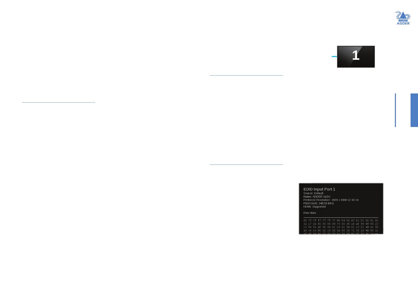
To view EDID source port details
Useful for troubleshooting purposes, you can view various details related to the EDID
information that is being presented to the video source(s) linked to the transmitter’s
HDMI input(s). This includes the source mode being used (Default, Cloned or Transparent),
the preferred resolution and pixel clock values as well as the whole raw hex data that is
being presented.
1 Access the AdderLink POD Manager.
2 On the left side, click the TransmitterConguration button (or click the
transmitter image within the System Overview).
3 Click the Show EDID port 1 or
Show EDID port 2 option. The EDID
information for the chosen port will be
shown
Ü
17
INSTALLATIONCONFIGURATIONOPERATION
FURTHER
INFORMATION
INDEX
Systemconguration
Within the AdderLink POD Manager click the SystemConguration button to display
the System conguration page:
In this page you can:
Congure access details for the network port,
Manage authorized users and their access passwords,
Check and upgrade the rmware contained within the transmitter and/or any receiver
units connected to it.
Tocongureaccessdetailsforthenetwork port
1 Access the AdderLink POD Manager.
2 On the left side, click the SystemConguration button.
3 Click the Network Settings button. The following page will be displayed:
4 If required, change the setting of the Use DHCP option. When set to Enabled, the
transmitter unit will attempt to contact a local DHCP (Dynamic Host Conguration
Protocol) server in order to automatically gain all of the necessary network settings.
When enabled, no other network settings are required and the other network options
will all become non-editable and you can skip to step 6.
Note: When you use the DHCP option, the IP address for the transmitter will be set by the
DHCP server and the transmitter will move to that address. To discover the IP address it will
be necessary to view DHCP server logs or interrogate the DHCP server. It may be possible
to congure the DHCP server to use a particular address for the transmitter. If you cannot
connect to the transmitter after switching to DHCP mode, see the Troubleshooting section for
recovery details.
5 If the Use DHCP option is set to Disabled, you need ensure that the remaining network
options are appropriate for your installation. Change the System IP Address and System
Netmask options if required. If access from beyond the local network is required,
ensure that the System IP Gateway entry matches that of your local network gateway.
Note: When you change the System IP Address and click Save, the transmitter will move to
that new address and you will need to access it again at the new address. If Logon security is
enabled, you will be prompted afresh for your username and password.
6 When all settings are complete, click the Save button to apply your changes.
18
INSTALLATIONCONFIGURATIONOPERATION
FURTHER
INFORMATION
INDEX
To manage authorized users and their passwords
1 Access the AdderLink POD Manager.
2 On the left side, click the SystemConguration button.
3 Click the User Accounts option. The following page will be displayed:
4 To add or edit a user, select one of the six user
locations and then click the Edit User button
to display the following options
Ü
5 Enter/edit the required Username and Password.
Usernames and passwords can consist of up to sixteen alphanumeric characters.
Passwords can also include keyboard symbols.
Usernames and passwords are case sensitive.
6 Click the Save button to apply your changes and return to the previous page.
Note: If you edit the username and/or password of the account with which you are currently
logged on, when you next attempt to change pages you will be logged off and prompted for
your username and password.
Tocheckandupgradermware
1 Download the latest upgrade le from the Adder Technology website (www.adder.com):
View the Technical Support > Updates section.
2 Access the AdderLink POD Manager.
3 On the left side, click the SystemConguration button.
4 Click the Firmware Upgrade option. The transmitter will scan all ports to
determine the rmware versions of all connected receivers. The results are then
shown within the Upgrade page together with the rmware version of the transmitter:
By default, only the transmitter option will be ticked. If necessary, change this to
determine which devices should be included within the upgrade process.
5 Click the Continue button. However, if you wish to abort the upgrade process at this
point, click the Reboot button.
6 Click the Upload button to display a le dialog.
7 Use the le dialog to locate the upgrade le that you downloaded earlier and click
OK.
Note: If you select a le which is not an upgrade le, an upgrade failure message will be
displayed. Click the Reboot button before attempting another upgrade.
If the le is correct, the upgrade process will commence to all devices that are ticked
within the list. The POD Manager page will indicate that uploading is in progress; also
the orange indicators on the transmitter’s output ports will cease ashing for the
duration.
8 When the upgrade process is complete, click the Reboot button to take the
transmitter and the receivers through a cold restart cycle.
19
INSTALLATIONCONFIGURATIONOPERATION
FURTHER
INFORMATION
INDEX
In operation, most AdderLink DV installations require no intervention once congured.
The transmitter unit takes care of all connection control behind the scenes and
AdderLink POD Manager provides suitable management tools for remote monitoring.
MANAGING THE INSTALLATION
The AdderLink POD Manager provides a clear and intuitive overview of the installation
that allows you to take swift action if necessary.
To display the System Overview page within AdderLink POD Manager
1 Use a computer that is directly or indirectly (i.e. via a network switch) connected
to the ALDV104T transmitter. If you need to make a temporary connection, see the
section Accessing the AdderLink POD Manager.
2 Run a web browser on your computer and enter the IP address of the ALDV104T
transmitter. The default setting is: 192.168.1.22
The System Overview page of the AdderLink POD Manager should be shown:
Operation
Within the AdderLink POD Manager you can:
View the real-time overview of the installation. See the section System overview
elements for explanations of the various line and screen colors.
Ensure that the graphical view of installation is fully updated.
See Rescanning the System Overview.
React to an input source failure and switch to the alternative input if available.
See the section Changing to an alternative input source.
Enable and disable all screens (such that they are sent into standby mode when disabled).
See the section Enabling and disabling all screens.
Make alterations to key transmitter or receiver settings.
Administer network settings, user accounts and rmware upgrades.
Use the Rescan System
option to ensure the
displayed details are
fully up to date.
For explanations of the various line
and screen colors, please see the
section System overview elements.
HT
  • Page 1 1
  • Page 2 2
  • Page 3 3
  • Page 4 4
  • Page 5 5
  • Page 6 6
  • Page 7 7
  • Page 8 8
  • Page 9 9
  • Page 10 10
  • Page 11 11
  • Page 12 12
  • Page 13 13
  • Page 14 14
  • Page 15 15
  • Page 16 16
  • Page 17 17
  • Page 18 18
  • Page 19 19
  • Page 20 20
  • Page 21 21
  • Page 22 22
  • Page 23 23
  • Page 24 24
  • Page 25 25
  • Page 26 26
  • Page 27 27
  • Page 28 28
  • Page 29 29
  • Page 30 30
  • Page 31 31
  • Page 32 32
  • Page 33 33

ADDER DV104T User manual

Category
Video switches
Type
User manual

Ask a question and I''ll find the answer in the document

Finding information in a document is now easier with AI