ATTENTION: Install in accordance with national and local building and electrical codes.
!
Page 4
23
24
25
Cable Gripper Installation
26
Suspension Cable Installation
27
Suspension Cable Adjustment
28
Power Cord Installation 29
Power Cord Installation
30 Fixture Installation
OPTIONAL: Battery Pack Wiring
Battery pack installation requires the installation of a
second flexible conduit for wiring. This process
requires running 2 low voltage wires from driver pod
for connection to battery pack test light/switch.
OPTIONAL: Battery Pack Wiring
wire cover
To complete fixture installation, refer to supplied
fixture installation instructions and layout drawings.
Repeat steps 18 & 19 to add
one more exible conduit
run for baery pack wiring.
Align canopy bushing with coupling and install
canopy, spacer and cable gripper as shown. Fully
tighten gripper against 1/4”-20 bolt.
IMPORTANT: From above ceiling, tighten nut
against canopy to secure all components.
canopy
spacer
cable gripper
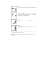
Insert suspension cable inside gripper and push
through exit side.
IMPORTANT: Ensure end of suspension cable is
visible through exit port of cable gripper.
suspension cable
release spring
Cable adjustment is done by pressing release spring.
CAUTION: Ensure fixture is fully supported before
any adjustments are made After final adjustments,
trim excess cable below canopy.
Refer to supplied xture
installaon instrucons.
Insert fixture low voltage power cord through
canopy hole and feed all the way into driver pod
housing for wiring connections.
power cord
Trim excess power cord and complete wiring
connections inside driver pod housing.
After all connections are complete, re-install driv-
er pod cover and screws removed in step 19.
Install supplied conduit elbow to bracket with con-
duit and connector (supplied by others). Remove
elbow cover and have wiring ready for splicing test
light/switch installed in canopy in step 22 on page 3.
Re-install elbow cover after all connections are done.
elbow


