Page is loading ...

IPN73-BA
Contents
• Specications summary
• Motherboard layout
• Rear panel connectors
• Function selectors
• Status indicators
• Internal connectors
%,26VHWXSSURJUDP
September 2008 (rev.3)

2
IPN73-BA motherboard layout reference
Specications summary
(Specications are subject to change without notice.)
CPU
LGA775 socket for Intel
®
Core™ 2 Quad / Core™ 2 Duo / Pentium
®
D /
Pentium
®
4 / Celeron
®
/ compatible with Intel
®
06 / 05B / 05A processors
(Conroe / Presler / Cedar Mill / Smitheld / Prescott / Conroe-L / Kentseld /
Wolfdale / Yorkeld) TDP: 95W
CPU Features
Supports Intel
®
next generation 45nm CPU
Supports Enhanced Intel SpeedStep
®
Technology (EIST)
Supports Intel
®
Hyper-Threading Technology
Chipset
North Bridge: NVIDIA GeForce 7100 / nForce 630i
Front Side Bus
1333 / 1066 / 800 / 533 MHz
Memory
Single-channel memory architecture
2 x 240-pin DIMM sockets support unbufferred non-ECC DDR2
800/667/ 533 memory modules, up to 4 GB total system memory
Expansion Slots
1 x PCI Express x16 slot
1 x PCI Express x1 slot
2 x PCI slots
Audio
Azalia Realtek ALC883 8-channel CODEC
1 x Coaxial S/PDIF out port
Supports jack-dectect and Anti Pop Function
Supports VISTA Premium OS
Storage
Southbridge:
- 1 x Ultra DMA 133
- 4 x Serial ATA 3Gb/s devices
- RAID 0, RAID 1, RAID 0+1, RAID 5, and JBOD conguration
LAN
Realtek 8211B Gigabit
USB
Supports up to 10 USB 2.0 ports (6 ports at mid-board, 4 ports at rear
panel
Rear panel
1 x HDMI port
1 x LAN (RJ-45) port
4 x USB 2.0 / 1.1 ports
1 x VGA port
1 x PS/2 keyboard port (purple)
1 x PS/2 mouse port (green)
8-channel audio I/O ports

3
IPN73-BA motherboard layout reference
Specications summary
Internal connectors
1 x Fl
oppy disk drive connector
1 x CD
audio in connector
1 x 24
-pin ATX power connector
1 x 4-pin ATX 12 V power connector
3 x USB connectors for additional six USB 2.0 ports
1 x S/
PDIF out connector
1 x Front panel audio connector
1 x CPU Fan connector
1 x Chassis fan connector
1 x Power fan connector
1 x Speaker conncetor
1 x System panel connector
VGA
GeForce 7100 GPU supports maximum resolution of
1920 x1440 bpp (@ 75Hz)
BIOS features
8 Mb
Flash ROM, Award BIOS, PnP, DMI2.0, WfM2.0, ACPI v2.0a,
SMBI
OS 2.5
Powe
r Requirement
ATX power supply (with 24-pin and 4-pin 12V plugs)
ATX 12V 2.0 compliant
Manageability
Wake on LAN, PME Wake up supported
For
m factor
MicroATX Form Factor: 9.6 inch x 8.6 inch
(Specications are subject to change without notice.)

4
IPN73-BA motherboard layout reference
Motherboard layout
DDR2 DIMM2 (64 bit,240-pin module)
DDR2 DIMM1 (64 bit,240-pin module)
PCI1
PCI2
PCIEX1_1
PCIEX16
EATXPWR
PRI_IDE
SATA2SATA1
SATA3SATA4
F_PANEL
SPEAKER
IPN73-BA
FLOPPY
CR2032 3V
Lithium Cell
CMOS Power
AAFP
Super I/O
USB56 USB78 USB910
SPDIF_OUT
8Mb
BIOS
ALC883
LAN_USB12
AUDIO
PS/2KBMS
T: Mouse
B: Keyboard
USB34
ATX12V
PS2_USBPW
CLRTC
CD
LGA775
PWR_FAN
CHA_FAN
CPU_FAN
USBPW5-10
MCP73PV
SB_PWR
RTL
8211B
ASM
4136
HDMI
VGA
CD
Connector
USB
Connector
USB Power
Selector
Speaker
Connector
Panel
Connector
CPU Fan
Connector
Power Fan
Connector
CPU
Socket
Power
Connector
AAFP
SPDIF
Chassis Fan
PS/2 USB Power
Connector
Selector
Connector
Connector
PS/2
Connectors
HDMI
Connector
VGA
Connector
Audio
Connectors
LAN & USB
Connectors
USB
Connector
PCI X1
Connector
PCI X16
Connector
PCI
Connectors
Clear RTC
Selector
Stand-by
power
Indicator
SATA
Connectors
Power
Connector
Memory
Sockets
IDE
Connector
BUZZER
5
IPN73-BA motherboard layout reference
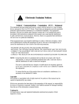
Rear panel connectors
1. PS/2 mouse port (green). This port is for a PS/2 mouse.
2. Video Graphics Adapter (VGA) port. This 15-pin port is for a VGA monitor or other VGA-compatible
devices.
3.
LAN (RJ-45) port. Supported by 5HDOWHN Gigabit LAN controller, this port allows Gigabit connection
to a Local Area Network (LAN) through a network hub. Refer to the table below for the LAN port LED
indications.
4. Rear Speaker Out port (black). This port connects the rear speakers in a 4-channel, 6-channel, or
8-channel audio conguration..
5. Center / Subwoofer port (orange). This port connects the center / subwoofer speakers.
6. Line In port (light blue). This port connects the tape, CD, DVD player, or other audio sources.
7. Line Out port (lime). This port connects a headphone or a speaker. In 4-channel, 6-channel, and
8-channel conguration, the function of this port becomes Front Speaker Out.
8. Microphone port (pink). This port connects a microphone.
9. Side Speaker Out port (gray). This port connects the side speakers in an 8-channel audio congu-
ration.
10.
USB 2.0 ports 1 and 2. These two 4-pin Universal Serial Bus (USB) ports are available for connect-
ing USB 2.0 devices.
11.
USB 2.0 ports 3 and 4. These two 4-pin Universal Serial Bus (USB) ports are available for connect-
ing USB 2.0 devices.
12. HDMI port. This port is for a High-Denition Multimedia Interface (HDMI) connector, and is HDCP
compliant allowing playback of HD DVD, Blu-Ray and other protected content
13.
PS/2 keyboard port (purple). This port is for a PS/2 keyboard.
Audio 2, 4, 6, or 8-channel conguration
Port Headset
2-channel
4-channel 6-channel 8-channel
Light Blue Line In Line In Line In Line In
Lime Line Out Front Speaker Out Front Speaker Out Front Speaker Out
Pink Mic In Mic In Mic In Mic In
Orange – – Center/Subwoofer Center/Subwoofer
Black – Rear Speaker Out Rear Speaker Out Rear Speaker Out
Gray – – – Side Speaker Out
Activity/Link LED Speed LED
Status Description Status Description
OFF No link OFF 10 Mbps connection
ORANGE Linked ORANGE 100 Mbps connection
BLINKING Data activity GREEN 1 Gbps connection
LAN port LED indications
SPEED
Indicator
ACT/LINK
Indicator
LAN port
4
6
5
7
8
910111213
1 2 3

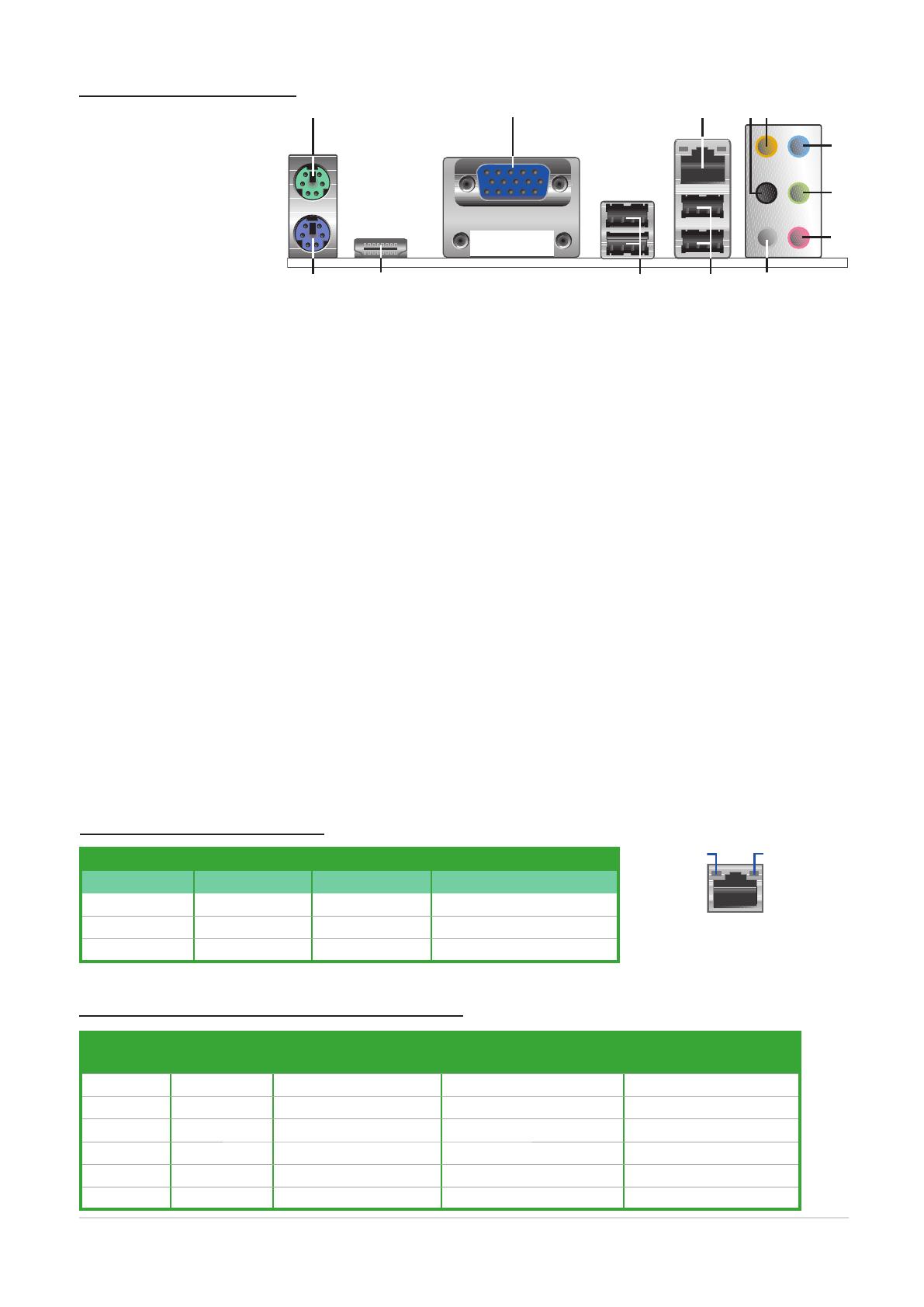
7
IPN73-BA motherboard layout reference
IPN73-BA
Floppy Disk Drive Connector
IPN73-BA Speaker Out Connector
IPN73-BA
IDE Connector
IPN73-BA Digital Audio Connector
+5V
SPDIFOUT
GND
SPDIF_OUT
IPN73-BA
Internal Audio Connector
Internal connectors
IPN73-BA
CPU Fan Connector
IPN73-BA
System Panel Connector
F_PANEL
Ground
PLED-
PWR
PLED+
GND
Reset
HDLED+
HDLED-
+HDLED
RESET
PLED
PWRBTN
IPN73-BA
Power Fan Connector
GND
Rotation
+12V
PWR_FAN
8
IPN73-BA motherboard layout reference
IPN73-BA
SATA
Connectors
IPN73-BA Front Panel Audio Connector
HP_HD
MIC2_L
HP_R
HP_L
MIC2_JD
Jack_Sense
MIC2_R
PRESENSE#
AGND
AAFP
Azalia-compliant
pin definition
IPN73-BA
USB 2.0 Connectors
Internal connectors (cont.)
IN73-BA ATX Power Connector
ATX12V
+12V DC
GND
+3 Volts
+3 Volts
Ground
+5 Volts
+5 Volts
Ground
Ground
Power OK
+5V Standby
+12 Volts
-5 Volts
+5 Volts
+3 Volts
-12 Volts
Ground
Ground
Ground
PSON#
Ground
+5 Volts
+12 Volts
+3 Volts
+5 Volts
Ground
EATXPWR
+12V DC
GND

BIOS setup program
This motherboard supports a programmable Serial Peripheral Interface (SPI) chip
that you can update using the provided utility Managing and updating your BIOS.
Use the BIOS Setup program when you are installing a motherboard, reconguring
your system, or prompted to “Run Setup”. This section explains how to congure
your system using this utility.
Even if you are not prompted to use the Setup program, you can change the
conguration of your computer in the future. For example, you can enable the
security password feature or change the power management settings. This
requires you to recongure your system using the BIOS Setup program so that the
computer can recognize these changes and record them in the CMOS RAM of the
SPI chip.
The SPI chip on the motherboard stores the Setup utility. When you start up the
computer, the system provides you with the opportunity to run this program. Press
<Del> during the Power-On Self-Test (POST) to enter the Setup utility. Otherwise,
POST continues with its test routines.
If you wish to enter Setup after POST, reboot the system by doing any of the
following procedures:
• Restart using the OS standard shut-down procedure.
• Press <Ctrl>+<Alt>+<Del> simultaneously.
• Press the reset button on the system chassis.
• Press the power button to turn the system off then back on.
• The default BIOS settings for this motherboard apply for most conditions
to ensure optimum performance. If the system becomes unstable after
changing any BIOS settings, load the default settings to ensure system
compatibility and stability. Select the Load Default Settings item under the
Exit Menu.
• The BIOS setup screens shown in this section are for reference purposes
only, and may not exactly match what you see on your screen.
Using the power button, reset button, or the <Ctrl>+<Alt>+<Del> keys to
force reset from a running operating system can cause damage to your data
or system. We recommend to always shut-down the system properly from the
operating system.
The Setup program is designed to make it as easy to use as possible. Being a
menu-driven program, it lets you scroll through the various sub-menus and make
your selections from the available options using the navigation keys.
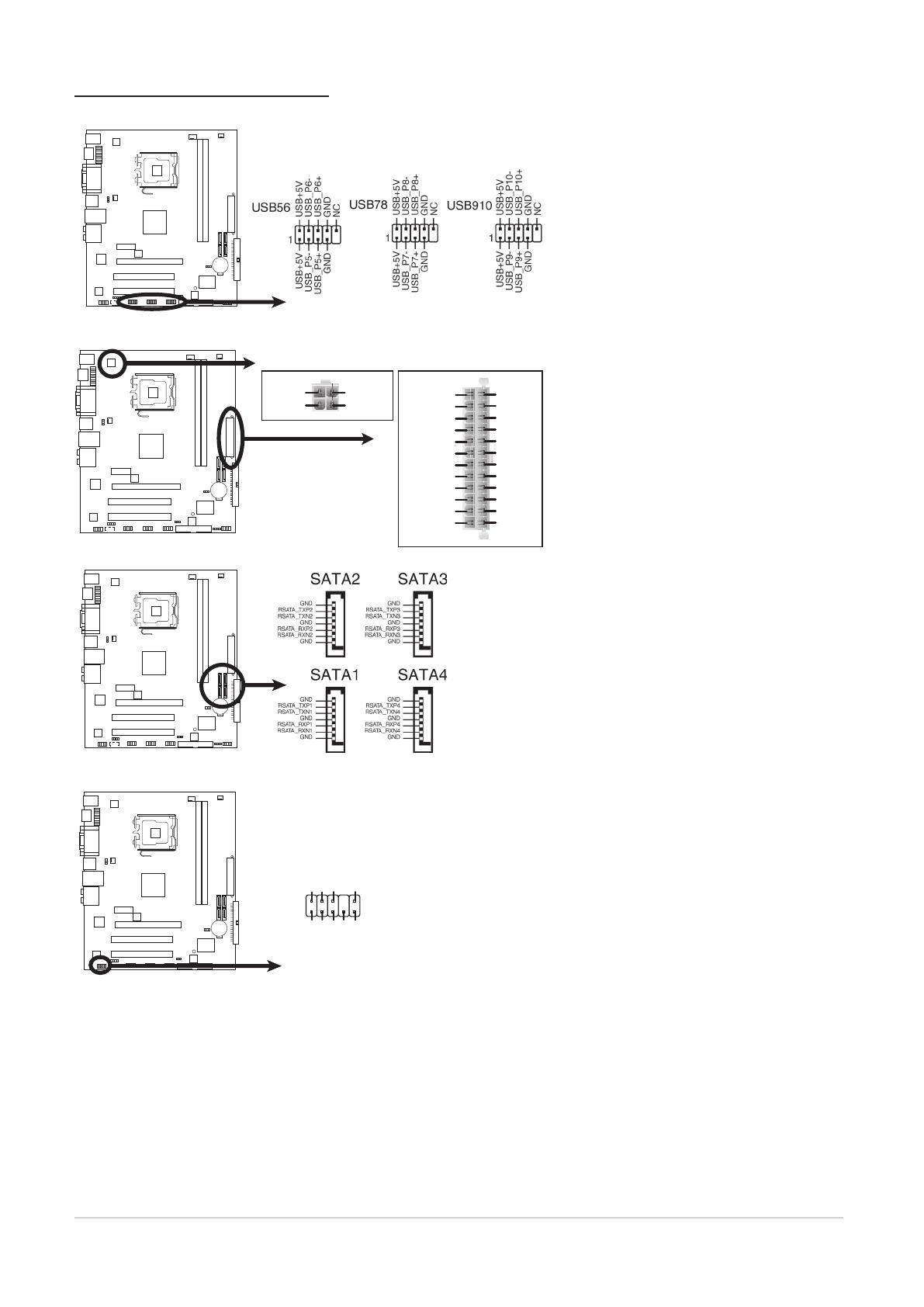
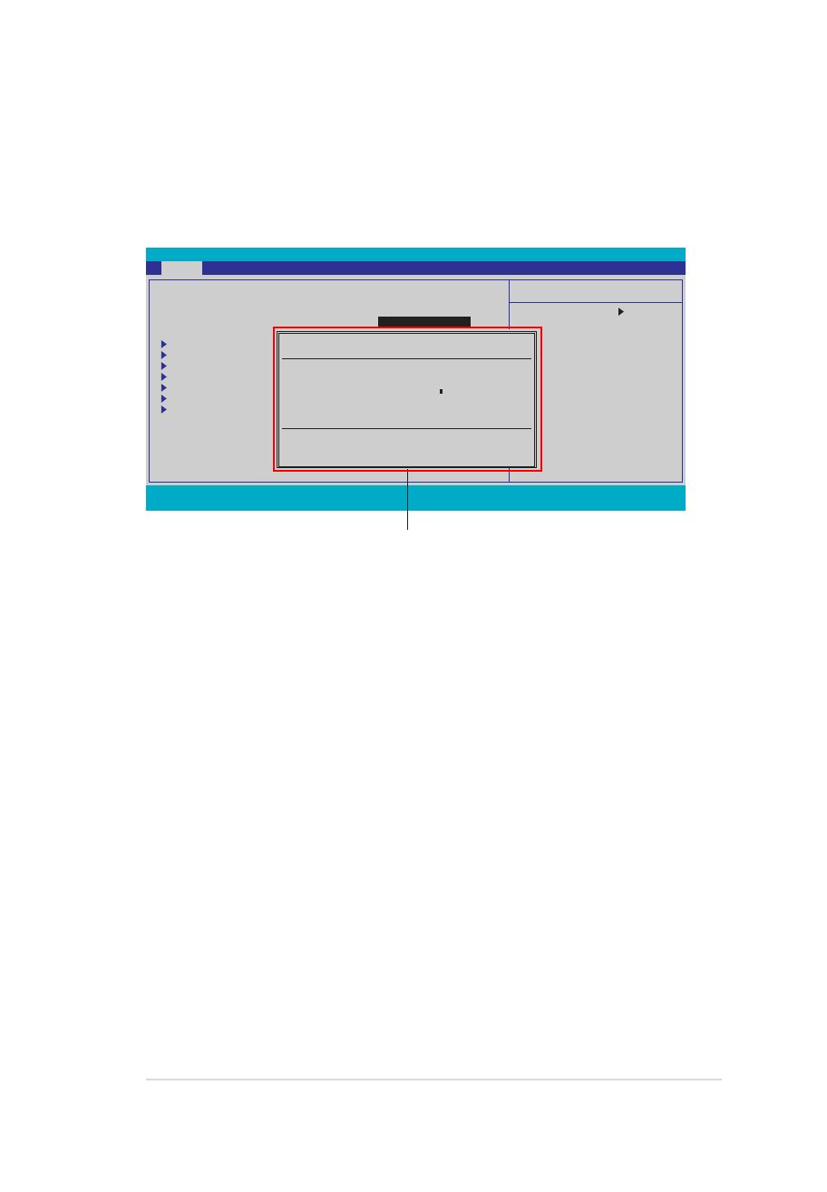
BIOS menu screen
Menu bar
The menu bar on top of the screen has the following main items:
Main
For changing the basic system conguration
Advanced For changing the advanced system settings
Power For changing the advanced power management (APM)
conguration
Boot For changing the system boot conguration
Exit
For selecting the exit options and loading default
settings
To select an item on the menu bar, press the right or left arrow key on the keyboard
until the desired item is highlighted.
• The BIOS setup screens shown in this chapter are for reference purposes
only, and may not exactly match what you see on your screen.
Select Menu
Item Specic Help
Change the day, month,
year and century.
Legend bar
General helpMenu bar
Sub-menu items
Conguration elds
Menu items
Phoenix-AwardBIOS CMOS Setup Utility
Main Advanced Power Boot Tools Exit
F1:Help ↑↓ : Select Item -/+: Change Value F5: Setup Defaults
ESC: Exit →←: Select Menu Enter: Select SubMenu F10: Save and Exit
System Time 0 : 7 : 28
System Date Tue, Jan 1 2008
Legacy Diskette A: [1.44M, 3.5 in.]
Primary IDE Master [None]
Primary IDE Slave [None]
SATA1 [None]
SATA2 [None]
SATA3 [ST380817AS]
SATA4 [None]
HDD SMART Monitoring [Disabled]
Installed Memory 512MB
Usable Memory 383MB

Menu items
The highlighted item on the menu bar displays the specic items for that menu.
For example, selecting Main shows the Main menu items.
The other items (Advanced, Power, Boot, and Exit) on the menu bar have their
respective menu items.
Sub-menu items
A solid triangle before each item on any menu screen means that the iteam has a
sub-menu. To display the sub-menu, select the item and press <Enter>.
Conguration elds
These elds show the values for the menu items. If an item is user-congurable,
you can change the value of the eld opposite the item. You cannot select an item
that is not user-congurable.
A congurable eld is enclosed in brackets, and is highlighted when selected. To
change the value of a eld, select it then press <Enter> to display a list of options.
Refer to “Pop-up window.”
Legend bar
At the bottom of the Setup screen is a legend bar. The keys in the legend bar allow
you to navigate through the various setup menus. The following table lists the keys
found in the legend bar with their corresponding functions.
Navigation Key Function
<F1> Displays the General Help screen
<F5> Loads setup default values
<Esc> Exits the BIOS setup or returns to the main menu from a
sub-menu
Left or Right arrow Selects the menu item to the left or right
Up or Down arrow Moves the highlight up or down between elds
Page Down or – (minus) Scrolls backward through the values for the highlighted eld
Page Up or + (plus) Scrolls forward through the values for the highlighted eld
<Enter> Brings up a selection menu for the highlighted eld
<F10> Saves changes and exit
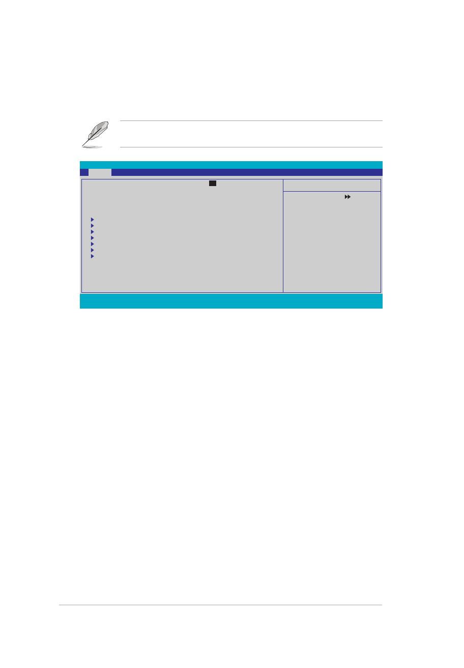
Pop-up window
Select a menu item then press <Enter> to display a pop-up window with the
conguration options for that item.
General help
At the top right corner of the menu screen is a brief description of the selected
item.
F1:Help ↑↓ : Select Item -/+: Change Value F5: Setup Defaults
ESC: Exit →←: Select Menu Enter: Select SubMenu F10: Save and Exit
Phoenix-Award BIOS CMOS Setup Utility
Main Advanced Power Boot Tools Exit
Select Menu
Item Specic Help
Species the capacity and
physical size of diskette
drive A.
Pop-up menu
System Time 0 : 14 : 36
System Date Tue, Jan 1 2008
Legacy Diskette A: [1.44M, 3.5 in.]
Primary IDE Master [ST321122A]
Primary IDE Slave [ASUS CDS520/A]
SATA1 [None]
SATA2 [None]
SATA3 [None]
SATA4 [None]
HDD SMART Monitoring [Disabled]
Installed Memory 512MB
Usable Memory 512MB
Legacy Diskette A:
Disabled ..... [ ]
720K , 3.5 in. ..... [ ]
1.44M, 3.5 in. ..... [ ]
↑↓ :Move ENTER:Accept ESC:Abort
IPN73-BA motherboard BIOS setup reference
F1:Help ↑↓↑↓ : Select Item -/+: Change Value F5: Setup Defaults
ESC: Exit →←→←: Select Menu Enter: Select SubMenu F10: Save and Exit
Phoenix-Award BIOS CMOS Setup Utility
Main Advanced Power Boot Tools Exit
Select Menu
Item Specic Help
Change the day, month,
year and century.
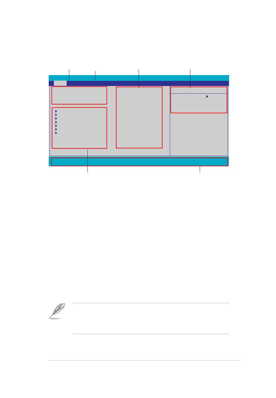
Main menu
When you enter the BIOS Setup program, the Main menu screen appears, giving
you an overview of the basic system information.
Refer to section “BIOS menu screen” for information on the menu screen
items and how to navigate through them.
System Time [xx:xx:xx]
Allows you to set the system time.
System Date [Day xx/xx/xxxx]
Allows you to set the system date.
Legacy Diskette A [1.44M, 3.5 in.]
Sets the type of oppy drive installed. Conguration options: [Disabled]
[720K , 3.5 in.] [1.44M, 3.5 in.]
System Time 0 : 18: 36
System Date Tue, Jan 1 2008
Legacy Diskette A: [1.44M, 3.5 in.]
Primary IDE Master [None]
Primary IDE Slave [None]
SATA1 [None]
SATA2 [None]
SATA3 [ST380817AS]
SATA4 [None]
HDD SMART Monitoring [Disabled]
Installed Memory 512MB
Usable Memory 383MB
IPN73-BA motherboard BIOS setup reference
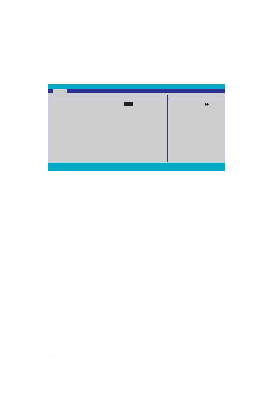
Primary IDE Master/Slave
While entering Setup, the BIOS automatically detects the presence of IDE devices.
There is a separate sub-menu for each IDE device. Select a device item then
press <Enter> to display the IDE device information.
The BIOS automatically detects the values opposite the dimmed items (Capacity,
Cylinder, Head, Sector and Transfer Mode). These values are not user-
congurable. These items show N/A if no IDE device is installed in the system.
PIO Mode [Auto]
Sets the PIO mode for the IDE device. Conguration options: [Auto] [Mode 0]
[Mode 1] [Mode 2] [Mode 3] [Mode 4]
UDMA Mode [Auto]
Disables or sets the UDMA mode. Conguration options: [Disabled] [Auto]
Primary IDE Master/Slave [Auto]
Select [Auto] to automatically detect an IDE hard disk drive. If automatic detection
is successful, the BIOS automatically lls in the correct values for the remaining
elds on this sub-menu. If the hard disk was already formatted on a previous
system, the setup BIOS may detect incorrect parameters. Select [Manual] to
manually enter the IDE hard disk drive parameters. If no drive is installed select
[None]. Conguration options: [None] [Auto] [Manual]
Access Mode [Auto]
The default [Auto] allows automatic detection of an IDE hard disk drive.
Select [CHS] for this item if you set the Primary IDE Master/Slave to [Manual].
Conguration options: [CHS] [LBA] [Large] [Auto]
F1:Help ↑↓ : Select Item -/+: Change Value F5: Setup Defaults
ESC: Exit →←: Select Menu Enter: Select SubMenu F10: Save and Exit
Phoenix-Award BIOS CMOS Setup Utility
Main
Select Menu
Item Specic Help
Primary IDE Master
PIO Mode [Auto]
UDMA Mode [Auto]
Primary IDE Master [Auto]
Access Mode [Auto]
Capacity 0 GB
Cylinder 0
Head 0
Sector 0
Transfer Mode None
IPN73-BA motherboard BIOS setup reference

Capacity
Displays the auto-detected hard disk capacity. This item is not congurable.
Cylinder
Shows the number of the hard disk cylinders. This item is not congurable.
Head
Shows the number of the hard disk read/write heads. This item is not congurable.
Sector
Shows the number of sectors per track. This item is not congurable.
Transfer Mode
Shows the Transfer mode. This item is not congurable.
After entering the IDE hard disk drive information into BIOS, use a disk utility,
such as FDISK, to partition and format new IDE hard disk drives. This is
necessary so that you can write or read data from the hard disk. Ensure to set
the partition of the Primary IDE hard disk drives to active.
Before attempting to congure a hard disk drive, ensure that you have the
correct conguration information supplied by the drive manufacturer. Incorrect
settings may cause the system to fail to recognize the installed hard disk.
IPN73-BA motherboard BIOS setup reference

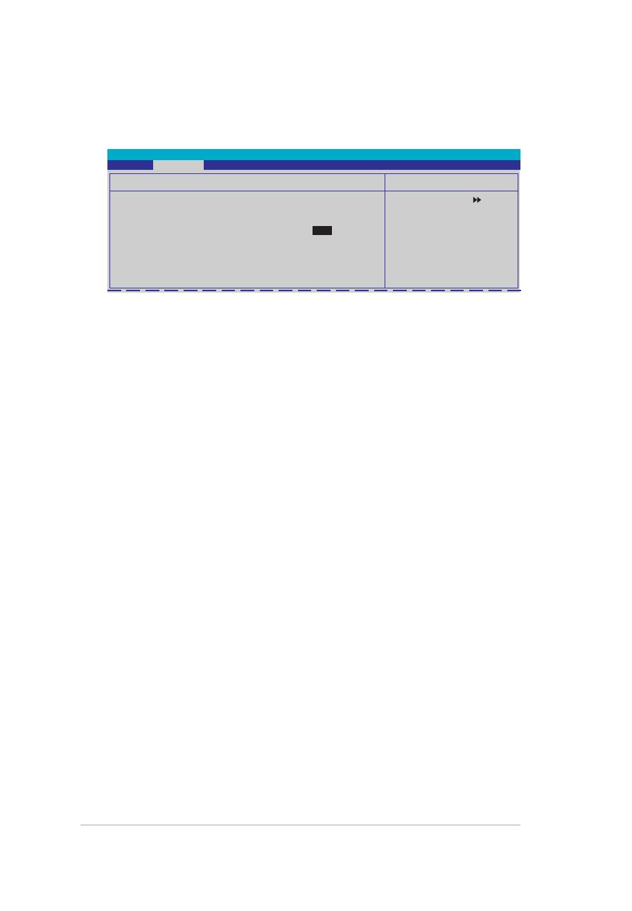
SATA 1-4
While entering Setup, the BIOS automatically detects the presence of Serial ATA
devices. There is a separate sub-menu for each SATA device. Select a device item
then press <Enter> to display the SATA device information.
The BIOS automatically detects the values opposite the dimmed items (Capacity,
Cylinder, Head, Precomp, Landing Zone and Sector). These values are not user-
congurable. These items show 0 if no SATA device is installed in the system.
Extended IDE Drive [Auto]
Selects the type of xed disk connected to the system.
Conguration options: [None] [Auto]
Access Mode [Auto]
Sets the sector addressing mode. Conguration options: [Large] [Auto]
Before attempting to congure a hard disk drive, ensure that you have the
correct conguration information supplied by the drive manufacturer. Incorrect
settings may cause the system to fail to recognize the installed hard disk.
Capacity
Displays the auto-detected hard disk capacity. This item is not congurable.
Cylinder
Shows the number of the hard disk cylinders. This item is not congurable.
Head
Shows the number of the hard disk read/write heads. This item is not congurable.
F1:Help ↑↓ : Select Item -/+: Change Value F5: Setup Defaults
ESC: Exit →←: Select Menu Enter: Select SubMenu F10: Save and Exit
Phoenix-Award BIOS CMOS Setup Utility
Main
Select Menu
Item Specic Help
Slects the type of
xed disk connected
to the system.
SATA 1
Extended IDE Drive [Auto]
Access Mode [Auto]
Capacity 0 MB
Cylinder 0
Head 0
Landing Zone 0
Sector 0
IPN73-BA motherboard BIOS setup reference

Landing Zone
Shows the number of landing zone per track. This item is not congurable.
Sector
Shows the number of sectors per track. This item is not congurable.
HDD SMART Monitoring [Disabled]
Allows you to enable or disable the HDD Self-Monitoring Analysis and Reporting
Technology (SMART) feature. Conguration options: [Disabled] [Enabled]
Installed Memory [xxx MB]
Shows the size of installed memory.
Usable Memory [XXX MB]
Shows the size of usable memory.
After entering the IDE hard disk drive information into BIOS, use a disk utility,
such as FDISK, to partition and format new IDE hard disk drives. This is
necessary so that you can write or read data from the hard disk. Ensure to set
the partition of the Primary IDE hard disk drives to active.
IPN73-BA motherboard BIOS setup reference

Advanced menu
The Advanced menu items allow you to change the settings for the CPU and other
system devices.
Take caution when changing the settings of the Advanced menu items. Incorrect
eld values can cause the system to malfunction.
Phoenix-Award BIOS CMOS Setup Utility
Main Advanced Power Boot Tools Exit
Select Menu
Item Specic Help
Jumperfree
CPU Conguration
Chipset
PCIPnP
Onboard Device Conguration
USB Conguration
F1:Help ↑↓ : Select Item -/+: Change Value F5: Setup Defaults
ESC: Exit →←: Select Menu Enter: Select SubMenu F10: Save and Exit
IPN73-BA motherboard BIOS setup reference
CPU Conguration
Select Menu
Item Specic Help
Thermal Monitor 1 (On
die throtting)
ThermalMonitor 2
Ratio & VID transition
)
Phoenix-Award BIOS CMOS Setup Utility
Advanced
CPU Internal Thermal Control [Auto]
Enables or disables the CPU internal thermal control.
Conguration options: [Auto] [Disabled]
Limit CPUID MaxVal [Disabled]
Enables or disables the Limit CPUID MaxVal technology.
Conguration options: [Disabled] [Enabled]
Enhanced C1 (C1E) [Disabled]
Enables or disables the Enhanced C1 (C1E) technology. The process lowers the
core to bus ratio and VID when physical process enters an enhance C1 state.
Conguration options: [Enable] [Disabled]
Execute Disable Bit [Enabled]
Enables or disables the processor’s XD bit feature.
Conguration options: [Enabled] [Disabled]
Virtualization Technology [Enabled]
Enables or disables the Virtualization technology. When enabled, a VMM can
utilize the additional hardware capabilities provided by Vanderpool Technology.
Conguration options: [Enable] [Disabled]
CPU Multiplier [7X]
Allows you to set the CPU multiplier. Conguration options: [Min.=0.0] [Max.=50.0]
Enhanced Intel SpeedStep(tm) Tech [Enabled]
Enables or disables the Enhanced Intel SpeedStep technology to adjust CPU
speed according to CPU workload. Conguration options: [Disabled] [Enabled]
CPU Conguration
CPU Type Inter(R) Core(TM)2 CPU
6300 @ 1.86GHz
CPU Speed 1.86GHz
Cache RAM 2048K
CPU Internal Thermal Control [Auto]
Limit CPUID MaxVal [Disabled]
Enhanced C1 (C1E) [Disabled]
Execute Disable Bit [Enabled]
Virtualization Technology [Enabled]
CPU Multiplier [ 7 x]
Enhanced Intel SpeedStep(tm) Tech.[Enabled]
IPN73-BA motherboard BIOS setup reference

Select Menu
Item Specic Help
Phoenix-Award BIOS CMOS Setup Utility
Advanced
Chipset
Spread Spectrum Control
Frame Buffer Size [128MB]
Primary Display Adapter [PCI-E]
Chipset
CPU/SATA/PCIE Spread Spectrum [Disabled]
Allows you to enable or disabled CPU/SATA/PCIE spread spectrum.
Conguration options: [Disabled] [Enabled]
Frame Buffer Size [128M]
Allows you to set the frame buffer size. Conguration options: [16M] [32M] [64M]
[128M] [256M]
Primary Display Adapter [PCI-E]
Allows you to select the graphics controller to use as the primary boot device.
Confguration options: [PCI] [Onboard] [PCI-E]
Spread Spectrum Control
Phoenix-Award BIOS CMOS Setup Utility
Advanced
Spread Spectrum Control
Select Menu
Item Specic Help
Plug & Play O/S [No]
When set to [No], the BIOS congures all the devices in the system. When set to
[Yes] and if you install a Plug and Play operating system, the operating system
congures the Plug and Play devices not required for boot.
Conguration options: [No] [Yes]
PCIPnP
Phoenix-Award BIOS CMOS Setup Utility
Advanced
Select Menu
Item Specic Help
CPU Spread Spectrum [Disabled]
SATA Spread Spectrum [Disabled]
PCIE Spread Spectrum [Disabled]
PCIPnP
Plug & Play O/S [No]
IPN73-BA motherboard BIOS setup reference

F1:Help ↑↓ : Select Item -/+: Change Value F5: Setup Defaults
ESC: Exit →←: Select Menu Enter: Select SubMenu F10: Save and Exit
Select Menu
Item Specic Help
Onboard Device Conguration
IDE Function SetupIDE Function Setup
Serial-ATA conguration
HD Audio Controller [Auto]
Front Panel Support Type [HD Audio]
HDMI Audio [Auto]
Intergade HDA Codec [SPDIF]
Onboard nVidia LAN [Enabled]
Onboard LAN Boot ROM [Disabled]
Serial Port1 Address [3F8/IRQ4]
Parallel Port Address [378/IRQ7]
Parallel Port Mode [ECP]
x EPP Mode Select EPP1.7
ECP Mode Use DMA [3]
Phoenix-Award BIOS CMOS Setup Utility
Advanced
Onboard Device Conguration
OnChip IDE Channel 0 [Enabled]
Allows you to enable or disable the OnChip IDE channel 0 controller.
Conguration options: [Disabled] [Enabled]
IDE DAM transfer access [Enabled]
Allows you to enable or disable IDE DMA transfer access .
Conguration options: [Disabled] [Enabled]
Serial-ATA Controller [Enabled]
Allows you to enable or disable the Serial-ATA controller.
Conguration options: [Disabled] [Enabled]
IDE Prefetch Mode [Enabled]
Allows you to enable or disable the IDE prefetch mode.
Conguration options: [Disabled] [Enabled]
IDE Function Setup
Select Menu
Item Specic Help
Phoenix-Award BIOS CMOS Setup Utility
Advanced
IDE Function Setup
OnChip IDE Channel0 [Enabled]
IDE DMA transfer access [Enabled]
Serial-ATA Controller [Enabled]
IDE Prefetch Mode [Enabled]
IPN73-BA motherboard BIOS setup reference
/