Hitachi C 8FSE User manual

Category
Mitre saws
Type
User manual

This manual is also suitable for

PRODUCT NAME
Hitachi Slide Compound Miter Saw
Models C 8FSE, C 8FSHE
Cutting various types of wood workpieces
Cutting workpieces of plywood, decoration panels, soft fiberboards and hard boards
Cutting aluminum sashes
The new slide compound miter saws Models C 8FSE and C 8FSHE are developed to bring to the European
market at the prices as low as the competitors’ products. The Model C 8FSHE is equipped with a laser marker
for easier alignment with the ink line and an LED light to illuminate the working surface brightly. In addition, the
Model C 8FSE that is mostly the same as the Model C 8FSHE except that it is not equipped with the laser
marker and the LED light is introduced in tandem with the Model C 8FSHE. With the new Models C 8FSE and
C
8FSHE
, we aim to enhance the share of
the
Hitachi
slide
compound
miter
MARKETING OBJECTIVE
APPLICATIONS
SELLING POINTS
International Sales Division
SPECIFICATIONS AND PARTS ARE SUBJECT TO CHANGE FOR IMPROVEMENT.
LIST Nos.
C 8FSE: E948
C 8FSHE: E949
Feb. 2008
C 8FSHE
C
<Same features as the conventional models>
Slide cutting
Press cutting
Miter cutting
Right and left bevel cutting
Compound miter and left bevel cutting
Splinter guard, also serving for cut alignment
Groove cutting
[ NEW FEATURES ]
Laser marker (Only the Model C 8FSHE)
LED light (Only the Model C 8FSHE)
Lightweight
Positive angle stoppers
Bevel cutting range: Left 48° to right 5°
High dust collecting performance
Soft grip handle
Legible scale
REMARK:
For more information about HANDLING INSTRUCTIONS, visit our website at:
http://www.hitachi-koki.com/manual_view_export/
Throughout this TECHNICAL DATA AND SERVICE MANUAL, a symbol(s) is(are) used in the place of
company name(s) and model name(s) of our competitor(s). The symbol(s) utilized here is(are) as follows:
Competitors
Symbols Utilized
Company Name Model Name
P1 DEWALT DW707
P2 DEWALT DW777
P3 DEWALT DW712
B BOSCH GCM8S
CONTENTS
Page
SELLING POINT DESCRIPTIONS-----------------------------------------------------------------------------------------1
SPECIFICATIONS --------------------------------------------------------------------------------------------------------------6
1. Specifications
-------------------------------------------------------------------------------------------------------------------------------- 6
COMPARISONS WITH SIMILAR PRODUCTS--------------------------------------------------------------------------8
1. Specification comparisons
------------------------------------------------------------------------------------------------------------- 8
PRECAUTIONS IN SALES PROMOTION------------------------------------------------------------------------------ 12
1. Safety instructions
----------------------------------------------------------------------------------------------------------------------- 12
2. Precautions requiring particular attention during sales promotion
------------------------------------------ 15
ADJUSTMENT AND OPERATIONAL PRECAUTIONS------------------------------------------------------------- 16
1. Confirmation of saw blade lower limit position
-------------------------------------------------------------------------- 16
2. Confirmation for use of sub fence (Optional accessory)
---------------------------------------------------------- 16
3. Position adjustment of laser line (Only the Model the C 8FSHE)
-------------------------------------------- 17
4. How to use the vise assembly
--------------------------------------------------------------------------------------------------- 18
5. Adjustment of table insert position
--------------------------------------------------------------------------------------------- 18
6. Cutting operation
------------------------------------------------------------------------------------------------------------------------- 19
ADJUSTMENT OF COMPONENTS ------------------------------------------------------------------------------------- 24
1. Bevel angle adjustment
-------------------------------------------------------------------------------------------------------------- 24
2. Ball bushing (Linear bearing)
----------------------------------------------------------------------------------------------------- 24
PACKING ----------------------------------------------------------------------------------------------------------------------- 25
REPAIR GUIDE---------------------------------------------------------------------------------------------------------------- 26
1. Precautions in disassembly and reassembly
---------------------------------------------------------------------------- 26
2. Troubleshooting guide
----------------------------------------------------------------------------------------------------------------- 43
STANDARD REPAIR TIME (UNIT) SCHEDULES-------------------------------------------------------------------- 48
Assembly diagram for C 8FSHE
Assembly diagram for C 8FSE
-1-
Laser marker (Only the Model C 8FSHE)
Use the laser marker for aligning with the ink line on the
workpiece.
(1) Cutting position can be properly adjusted by aligning the
positioning ink line with the laser line. There is no need to
make a long ink line on the workpiece.
(2) There is no need to lower the motor head to align with the
ink line because the laser marker makes a laser line on the
workpiece. In addition, cutting position can be easily
adjusted because the operator can hold the workpiece with
both hands to move.
(3) Cutting position can be easily adjusted because the laser
line can be aligned with an optionally angled ink line.
(4) Even the workpieces such as crown moldings and base
boards that have decorative surfaces and are difficult to be
made an ink line can be cut just by aligning the laser line
with the ink line on the fence side. The laser line is
adjusted to the width of the saw blade at the time of factory
shipment. Depending upon the user's cutting choice, the
laser line can be aligned with the left side of the cutting
width (saw blade) or the ink line on the right side. Adjust
the position of the laser line according to "Position
adjustment of laser line" on page 17.
LED light (Only the Model C 8FSHE)
The Model C 8FSHE is equipped with an LED light to light up
over a table brightly. The two LEDs incorporated in it light up the
materials and the point of the saw blade brightly. The LED light
can freely move at the time of right and left bevel cutting
because the support is flexible. Therefore, it lights up the
materials and the point of the saw blade brightly at any time.
Lightweight
The Model C 8FSE is most lightweight (14 kg) in the class of 8” (216 mm) slide compound miter saws
because the reinforcement rib of the table is placed in the most suitable position.
SELLING POINT DESCRIPTIONS
Lase
r
marke
r
Laser beam
Fig. 1-a
Fig. 1-b
Fig. 1-c
Fig. 2
(molding, base board, etc.)
-2-
Positive angle stoppers
The Models C 8FSE and C 8FSHE have positive angle
stoppers in the turn table at the right and the left of the 0°
center setting, at 15°, 22.5°, 31.6° and 45° settings.
Thanks to the positive angle stoppers, positioning can be
done more securely than the ball index method utilized in
the current Model C 8FB2. In addition, a lever is provided
at the lower tip of the turn table to secure or release the
positive angle stoppers.
Adjustment of the turn table and positioning can be easily
done while holding the side handle.
Bevel cutting range: Left 48° to right 5°
Possible range of bevel cutting is from left 48 degrees to right 5
degrees. By the simple operation of the set pin, you can set the
position of the right angle and left 45 degrees.
In addition, setting to approximately 30 degrees and 33.9
degrees for crown molding cutting can be done by this set pin.
High dust collecting performance
The dust collecting performance of the Models C 8FSE and C 8FSHE are remarkably higher than the other
models thanks to the adoption of new dust guide and gear case.
HITACHI
C 8FSE
C 8FSHE
C 8FB2
P1 and P2 P3 B
Press cutting *
1
(Size of the workpiece:
60 mm x 60 mm (2-3/8” x 2-3/8”))
75.0 25.0 5.9 31.3 62.2
Slide cutting *
2
(Size of the workpiece:
30 mm x 150 mm (1-3/16” x 5-29/32”))
80.0 45.0 11.0 72.3 74.5
Soft grip handle
The handles are widely covered with soft-touch elastomer (rubber-like soft resin).
It is slip-resistant and securely fits in the palm of a hand even if the gripping hand sweats.
Legible scale
The Models C 8FSE and C 8FSHE have legibly labeled angle scale and bevel scale while the current
Model C 8FB2 has the scale printed on the die casting.
Table 1
(%)
Maker
Model
*1: This is a method to cut a workpiece by shaking the motor head.
*2: This is a method to cut a workpiece by sliding the motor head from the front.
The dust collecting performance is obtained from the following formula:
Weight of sawdust accumulated in the dust bag (g)
Weight of all sawdust during cutting (g)
Dust collecting performance (%) = x 100
Fig. 3
Set pin
Fig. 4
Cutting
method
-3-
Slide cutting
HITACHI
C 8FSE
C 8FSHE
C 8FB2
P1 and P2 P3 B
Height x Width
(H x W)
65 x 312
(2-9/16” x 12-1/4”)
75 x 262
(2-15/16” x 10-5/6”)
with aux. board
width 30 (1-3/16”)
65 x 305
(2-9/16” x 12”)
75 x 265
(2-15/16” x 10-7/16”)
60 x 270
(2-3/8” x 10-3/8”)
70 x 300
(2-3/4” x 11-13/16”)
60 x 270
(2-3/8” x 10-3/8”)
Workpieces as wide as shown in Table 2 can be cut with the motor
head sliding. The lower limit position of the saw blade is factory-
adjusted so that workpieces up to 65 mm (2-9/16") high and 312 mm
(12-1/4") wide can be cut as shown in Fig. 6-a. When cutting a
workpiece of 75 mm (2-15/16") in height as indicated in [ ] in Table 2,
adjust the saw so that there is a clearance of 2 to 3 mm (3/32" to 1/8")
between the bottom surface of the head and the top surface of the
workpiece at the lower limit position of the saw blade as shown in Fig. 6-b. (See the Instruction Manual
"Lower limit position of saw blade when cutting a large workpiece.")
Please note that, when cutting in this position, it is necessary to use an auxiliary board of 30 mm (1-3/16")
wide so that the workpiece on the fence side can be cut fully in width.
Press cutting
HITACHI
C 8FSE
C 8FSHE
C 8FB2
P1 and P2 P3 B
Height x Width
(H x W)
65 x 65
(2-9/16” x 2-9/16”)
65 x 65
(2-9/16” x 2-9/16”)
60 x 60
(2-3/8” x 2-3/8”)
70 x 40
(2-3/4” x 1-9/16”)
60 x 68
(2-3/8” x 2-11/16”)
Press cutting with the head swiveling enables cutting square
workpieces as large as shown in Table 3 in a single sawing
operation. It is convenient for cutting narrow workpieces (Fig. 7).
Table 2
Unit: mm (inch)
Table 3
Unit: mm (inch)
Fig. 5
Fig. 7
Fig. 6-bFig. 6-a
Max.
cutting
d
im
e
n
s
i
o
n
Maker
Model
Maker
Model
Max.
cutting
d
im
e
n
s
i
o
n
-4-
Miter cutting
HITACHI
C 8FSE
C 8FSHE
C 8FB2
P1 and P2 P3 B
Right and
left 45°
Height x Width
(H x W)
65 x 220
(2-9/16” x 8-21/32”)
75 x 185
(2-15/16” x 7-1/4”)
with aux. board
width 20 (13/16”)
65 x 220
(2-9/16” x 8-21/32”)
60 x 190
(2-3/8” x 7-15/32”)
70 x 212
(2-3/4” x 6-11/32”)
60 x 190
(2-3/8” x 7-15/32”)
Right 57°
Height x Width
(H x W)
65 x 170
(2-9/16” x 6-11/16”)
75 x 140
(2-15/16” x 5-1/2”)
with aux. board
width 20 (13/16”)
65 x 175
(2-9/16” x 6-7/8”)
-
70 x 160
(2-3/4” x 6-5/16”)
60 x 155
(2-3/8” x 6-3/32”)
Wide workpieces as wide as shown in Table 4 can be cut
by swiveling the turn table (right and left).
The maximum cutting dimensions in [ ] in Table 4 are those
obtained by adjusting the lower limit position of the saw
blade indicated in Fig. 6-b, also with an auxiliary board.
Right and left bevel cutting
HITACHI
C 8FSE
C 8FSHE
C 8FB2
P1 and P2 P3 B
Left 45°
Height x Width
(H x W)
45 x 312
(1-25/32” x 12-1/4”)
50 x 252
(1-15/16” x 9-15/16”)
with aux. board
width 30 (1-3/16”)
45 x 305
(1-25/32” x 12”)
48 x 270
(1-7/8” x 10-3/8”)
50 x 300
(1-15/16” x 11-13/16”)
42 x 270
(1-21/32” x 10-3/8”)
Right 5°
Height x Width
(H x W)
60 x 312
(2-9/16” x 12-1/4”)
70 x 252
(2-3/4” x 9-15/16”)
with aux. board
width 30 (1-3/16”)
--
-
-
Table 4
Unit: mm (inch)
Table 5
Fig. 8
Fig. 9
Unit: mm (inch)
Maker
Model
Max.
cutting
d
im
e
n
s
i
o
n
Max.
cutting
d
im
e
n
s
i
o
n
Maker
Model
-5-
Compound miter and bevel cutting
HITACHI
C 8FSE
C 8FSHE
C 8FB2
P1 and P2 P3 B
Miter left/right
45°
Bevel left 45°
Height x Width
(H x W)
45 x 220
(1-25/32” x 8-21/32”)
50 x 170
(1-15/16” x 6-11/16”)
with aux. board
width 30(1-3/16”)
45 x 220
(1-25/32” x 8-21/32”)
48 x 190
(1-7/8” x 7-15/32”)
50 x 212
(1-15/16” x 6-11/32”)
42 x 190
(1-21/32” x 7-15/32”)
Miter left/right
45°
Bevel right
45°
Height x Width
(H x W)
60 x 220
(2-9/16” x 8-21/32”)
70 x 170
(2-3/4” x 6-11/16”)
with aux. board
width 30(1-3/16”)
----
By turning the turn table to the left or right and inclining the saw blade section (head) to the left or right, the
Models C 8FSE and C 8FSHE are capable of compound cutting (bevel and miter, see Figs. 10-a and 10-b)
of workpieces with the maximum dimensions shown in Table 6.
Splinter guard, also serving for cut alignment
When cutting the ends of a workpiece, splinters may drop on the saw blade and be cut into pieces. The
Models C 8FSE and C 8FSHE are equipped with a splinter guard to prevent such splinter cutting.
(Refer to "SELLING POINTS .") Safe cutting is also ensured in bevel cutting because the splinter guard
is tilted with the saw blade.
Groove cutting
The Models C 8FSE and C 8FSHE can cut grooves at desired depth by adjusting the 6-mm depth adjustment bolt
manually. (Refer to "Groove cutting procedures" described in the Instruction Manual for details.)
NOTE: The Models C 8FSE and C 8FSHE cannot cut grooves at constant depth unless the saw blade
slides in parallel with the base surface.
Table 6
Fig. 10-bFig. 10-a
Unit: mm (inch)
Max.
cutting
d
im
e
n
s
i
o
n
Maker
Model
Base surface
Workpiece
Saw blade
Slide direction
Groove
[Model P1 and P2]
Fig. 11-b
Base surface
Workpiece
Saw blade
6 mm depth adjustment bolt
Slide direction
Groove
[Model C 8FSE/C 8FSHE]
Fig. 11-a
-6-
1. Specifications
Model
C 8FSE/C 8FSHE
0°(Right angle)
65 mm x 312 mm (2-9/16” x 12-1/4”),
75 mm x 262 mm (2-15/16” x 10-5/6”) (with aux. board 30 mm (1-3/16”))
Left/right 45°
65 mm x 220 mm (2-9/16” x 8-21/32”),
75 mm x 185 mm (2-15/16” x 7-1/4”) (with aux. board 20 mm (13/16”))
Miter
Right 57°
65 mm x 170 mm (2-9/16” x 6-11/16”),
75 mm x 140 mm (2-15/16” x 5-1/2”) (with aux. board 20 mm (13/16”))
Left 45°
45 mm x 312 mm (1-25/32” x 12-1/4”),
50 mm x 252 mm (1-15/16” x 9-15/16”) (with aux. board 30 mm (1-3/16”))
Bevel
Right 5°
60 mm x 312 mm (2-3/8” x 12-1/4”),
70 mm x 252 mm (2-3/4” x 9-15/16”) (with aux. board 30 mm (1-3/16”))
Miter left/right 45°+
bevel left 45°
45 mm x 220 mm (1-25/32” x 8-21/32”),
50 mm x 170 mm (1-15/16” x 6-11/16”) (with aux. board 30 mm (1-3/16”))
Maximum
cutting
dimensions
Height x
Width
mm (inch)
Miter left/right 45°+
bevel right 5°
60 mm x 220 mm (2-3/8” x 8-21/32”),
70 mm x 170 mm (2-3/4” x 6-11/16”) (with aux. board 30 mm (1-3/16”))
Miter cutting ranges
Left 0° - 45°, Right 0° - 57°
Bevel cutting ranges
Left 0° - 48°, Right 0° - 5°
Compound (miter + bevel)
cutting ranges
Miter left 45° to right 45° + left bevel 0° to 45°
Miter left 45° to right 45° + right bevel 0° to 5°
Angle stopper positions
0°, Right/left 15°, 22.5°, 31.6° and 45°
Applicable saw blade
216 mm (8-1/2") external dia.
U.S.A./Canada Europe/Australia Others
Saw blade bore
15.9 mm (5/8”) 30 mm (1-11/64”) 25.4 mm (1”)
External diameter of applicable
saw blades
200 mm to 220 mm (7-7/8" to 8-21/32")
U.S.A./Canada Europe/Australia Others
Lower guard lock
Not provided Provided Not provided
Maximum output < 1 mW (CLASS II)
Wave length 400 nm to 700 nm
Laser marker
(Only the
Model
C 8FSHE)
Laser medium Laser diode
Power source type and voltage
AC single phase 50/60 Hz, 110 V, 120 V, 220 V to 240 V
Type of motor
AC single phase commutator series motor
Full-load current
110 V: 10 A, 120 V: 9.2 A, 220 V: 5 A, 230 V: 4.8 A, 240 V: 4.6 A
No-load rotation speed
5,500 min
-1
Max. output
Approx. 2,100 W
Main unit dimensions
(Width x depth x height)
555 mm x 790 mm x 485 mm (21-27/32" x 31-3/32" x 19-3/32")
Weight
C 8FSE 14 kg (31 lbs.) C 8FSHE 14.5 kg (32 lbs.)
Coating
Gunmetallic silver
Packaging
Corrugated cardboard box
Cord
Type: 2-conductor cabtire cable Length: 1.8 m (6 ft)
SPECIFICATIONS
-7-
Standard accessories
·
216 mm (8-1/2") TCT saw blade (15.9 mm (5/8”) bore, NT24,
Code No. 998840 for USA/CAN) --------------------- for wood cutting
·
216 mm (8-1/2") TCT saw blade (30 mm (1-11/64”) bore, NT24,
Code No. 998859 for Europe/AUS) ----------------- for wood cutting
·
216 mm (8-1/2") TCT saw blade (25.4 mm (1”) bore, NT24,
Code No. 998858 for others) ------------------------- for wood cutting
·
Dust bag
·
Vise ass’y
·
10 mm box wrench
·
Holder
·
Side handle
·
Sub fence (for USA/CAN)
Optional accessories
·
216 mm (8-1/2") TCT saw blade (15.9 mm (5/8”) bore, NT36,
Code No. 998860 for USA/CAN) ------------------- for wood cutting
·
216 mm (8-1/2") TCT saw blade (30 mm (1-11/64”) bore, NT36,
Code No. 998861 for Europe/AUS) --------------- for wood cutting
·
216 mm (8-1/2") TCT saw blade (25.4 mm (1”) bore, NT36,
Code No. 996210 for others) ----------------------- for wood cutting
·
216 mm (8-1/2") TCT saw blade (15.9 mm (5/8”) bore, NT60,
Code No. 998862 for USA/CAN) ---------- for aluminum sash cutting
·
216 mm (8-1/2") TCT saw blade (30 mm (1-11/64”) bore, NT60,
Code No. 998863 for Europe/AUS) ------ for aluminum sash cutting
·
216 mm (8-1/2") TCT saw blade (25.4 mm (1”) bore, NT60,
Code No. 996288 for other) ---------------- for aluminum sash cutting
·
Extension holder and stopper (Code No. 321553)
·
Crown molding vise ass’y (Code No. 329782)
(Including crown molding stopper (L))
·
Crown molding stopper (L) (Code No. 321374)
·
Crown molding stopper (R) (Code No. 321373)
·
Sub fence ass’y (Code No. 329464)
-8-
1. Specification comparisons
[For Europe and others (Except for the U.S.A and Canada)]
(Superior specifications:
)
Maker
HITACHI
Model name
C 8FSE/C 8FSHE
P1 P2 B
0 (Right angle)
65 x 312 (2-9/16” x 12-1/4”)
75 x 262 (2-15/16” x 10-5/6”)
(with aux. board 30 (1-3/16”))
60 x 270
(2-3/8” x 10-3/8”)
60 x 270
(2-3/8” x 10-3/8”)
60 x 270
(2-3/8” x 10-3/8”)
Left/right 45°
65 x 220 (2-9/16” x 8-21/32”)
75 x 185 (2-15/16” x 7-1/4”)
(with aux. board 20 (13/16”))
60 x 190
(2-3/8” x 7-15/32”)
60 x 190
(2-3/8” x 7-15/32”)
60 x 190
(2-3/8” x 7-15/32”)
Miter
Right 57°
65 x 170 (2-9/16” x 6-11/16”)
75 x 140 (2-15/16” x 5-1/2”)
(with aux. board 20 (13/16”))
--
60 x 155
(2-3/8” x 6-3/32”)
Left 45°
45 x 312 (1-25/32” x 12-1/4”)
50 x 252 (1-15/16” x 9-15/16”)
(with aux. board 30 (1-3/16”))
48 x 270
(1-7/8” x 10-3/8”)
48 x 270
(1-7/8” x 10-3/8”)
42 x 270
(1-21/32” x 10-3/8”)
Bevel
Right 5°
60 x 312 (2-3/8” x 12-1/4”)
70 x 252 (2-3/4” x 9-15/16”)
(with aux. board 30 (1-3/16”))
---
Miter left/right 45°+
bevel left 45°
45 x 220 (1-25/32” x 8-21/32”)
50 x 170 (1-15/16” x 6-11/16”)
(with aux. board 30 (1-3/16”))
48 x 190
(1-7/8” x 7-15/32”)
48 x 190
(1-7/8” x 7-15/32”)
42 x 190
(1-21/32” x 7-15/32”)
Maximum cutting dimensions: Height x Width mm (inch)
Miter left/right 45°+
bevel right 5°
60 x 220 (2-3/8” x 8-21/32”)
70 x 170 (2-3/4” x 6-11/16”)
(with aux. board 30 (1-3/16”))
--
-
Groove cutting width
Possible
(with bolt height
adjustment)
Impossible Impossible
Possible
(with screw height
adjustment)
Miter cutting ranges
Left 0°
-
45°
Right 0°
-
57°
Left 0°
-
50°
Right 0°
-
50°
Left 0°
-
50°
Right 0°
-
50°
Left 0°
-
50°
Right 0°
-
58°
Bevel cutting ranges
Left 0°
-
48°
Right 0°
-
Left 0°
-
48° Left 0°
-
48° Left 0°
-
45°
Miter left and right
-
45°
Bevel left 0°
-
45°
Compound
(miter + bevel)
cutting ranges
Miter left and right
-
45°
Bevel right 0°
-
Miter left and right
-
45°
Bevel left 0°
-
45°
Miter left and right
-
45°
Bevel left 0°
-
45°
Miter left and right
-
45°
Bevel left 0°
-
45°
Angle stopper positions
0°, Right/left 15°, 22.5°,
31.6° , 45°
0°, Right/left 15°,
22.5°, 30°, 45°, 50°
0°, Right/left 15°,
22.5°, 30°, 45°, 50°
0°, Right/left 15°,
22.5°, 30°, 45°
Saw blade external
diameter mm (inch)
(No. of teeth)
216 (8-1/2") (24P) 216 (8-1/2") (24P) 216 (8-1/2") 216 (8-1/2") (24P)
COMPARISONS WITH SIMILAR PRODUCTS
-9-
Maker
HITACHI
Model name
C8FSE/C8FSHE
P1 P2 B
Laser marker
Provided Not provided Not provided Provided
Laser output
< 1 mW
--
< 1 mW
Light
Provided (2 LEDs) Not provided Not provided Provided
Full-load current (A)
230 V - 4.8 A 230 V - 5.6 A 230 V 230 V - 6.1 A
Motor
No-load revolution
(min
-1
)
5,500 6,700 6,300 5,000
Insulation structure
Double insulation Double insulation Double insulation Double insulation
Splinter guard
Provided Provided Not provided Not provided
Type of angle stopper
Positive stopper Positive stopper Positive stopper Positive stopper
Sub fence
Not provided (Option) Not provided
Provided Not provided
Capacity of dust bag (l)
2
-
2
Main unit dimensions
[Width x Depth x Height]
mm (inch)
555 x 790 x 485
(21-27/32" x 31-3/32"
x 19-3/32")
460 x 560 x 590
(18-1/8” x 22-1/16”
x 23-7/32”)
460 x 560 x 590
(18-1/8” x 22-1/16”
x 23-7/32”)
450 x 610 x 510
(17-23/32” x 24”
x 20-3/32”)
Product weight kg (lbs.)
C 8FSE: 14 (31)
C 8FSHE: 14.5 (32)
14.5 (32) 14 (31) 15 (33.1)
Standard accessories
·
216 mm (8-1/2") TCT
saw blade (NT24)
for wood cutting
-------1
·
Dust bag --------------1
·
Vise ass’y ------------1
·
10 mm box wrench ---1
·
Holder ----------------1
·
Sub fence-------------1
(for USA/CAN)
·
216 mm (8-1/2") TCT
saw blade (NT24)
for wood cutting
--- 1
·
Hex. bar wrench -- 2
·
Fence insert------- 1
·
216 mm (8-1/2") TCT
saw blade
for wood cutting
--- 1
·
Hex. bar wrench -- 2
·
Dust bag ----------1
·
Dust extraction
nozzles
----------- 2
·
216 mm (8-1/2")
TCT saw blade
(NT24)
---------1
·
Vise ass’y ------1
·
Hex. bar wrench
-----------------1
Optional accessories
·
Extension holder and
stopper
·
Crown molding vise
ass’y (Including crown
molding stopper (L))
·
Crown molding
stopper (L)
·
Crown molding
stopper (R)
·
Legstand
·
Vise ass’y
· Roller table
·
Length stop for short
workpieces
·
Legstand
·
Vise ass’y
· Roller table
·
Length stop for short
workpieces
·
Dust extraction tubes
·
Three-way connector
·
Extension bars
·
216 mm (8-1/2")
TCT saw blade
(NT48)
-10-
[For the U.S.A and Canada]
(Superior specifications:
)
Maker
HITACHI
Model name
C 8FSE/C 8FSHE C 8FB2
P3
0° (Right angle)
65 x 312 (2-9/16” x 12-1/4”)
75 x 262 (2-15/16” x 10-5/6”)
(with aux. board 30 (1-3/16”))
65 x 305 (2-9/16” x 12”)
75 x 265 (2-15/16” x 10-7/16”)
70 x 300
(2-3/4” x 11-13/16”)
Left/right 45°
65 x 220 (2-9/16” x 8-21/32”)
75 x 185 (2-15/16” x 7-1/4”)
(with aux. board 20 (13/16”))
65 x 220
(2-9/16” x 8-21/32”)
70 x 212
(2-3/4” x 6-11/32”)
Miter
Right 57°
65 x 170 (2-9/16” x 6-11/16”)
75 x 140 (2-15/16” x 5-1/2”)
(with aux. board 20 (13/16”))
65 x 175
(2-9/16” x 6-7/8”)
70 x 160
(2-3/4” x 6-5/16”)
Left 45°
45 x 312 (1-25/32” x 12-1/4”)
50 x 252 (1-15/16” x 9-15/16”)
(with aux. board 30 (1-3/16”))
45 x 305
(1-25/32” x 12”)
50 x 300
(1-15/16” x 11-13/16”)
Bevel
Right 5°
60 x 312 (2-3/8” x 12-1/4”)
70 x 252 (2-3/4” x 9-15/16”)
(with aux. board 30 (1-3/16”))
--
Miter left/right 45°+
bevel left 45°
45 x 220 (1-25/32” x 8-21/32”)
50 x 170 (1-15/16” x 6-11/16”)
(with aux. board 30 (1-3/16”))
45 x 220
(1-25/32” x 8-21/32”)
50 x 212
(1-15/16” x 6-11/32”)
Maximum cutting dimensions: Height x Width mm (inch)
Miter left/right 45°+
bevel right 5°
60 x 220 (2-3/8” x 8-21/32”)
70 x 170 (2-3/4” x 6-11/16”)
(with aux. board 30 (1-3/16”))
--
Groove cutting width
Possible
(with bolt height adjustment)
Possible
(with screw height
adjustment)
Possible
(with screw height
adjustment)
Miter cutting ranges
Left 0° - 45°
Right 0° - 57°
Left 0° - 45°
Right 0° - 57°
Left 0° - 50°
Right 0° - 60°
Bevel cutting ranges
Left 0° - 48°
Right 0° - 5°
Left 0° - 45°
Left 0° - 48°
Right 0° - 2°
Miter left and right
0° - 45°
Bevel left 0° - 45°
Compound
(miter + bevel)
cutting ranges
Miter left and right
0° - 45°
Bevel right 0° - 5°
Miter left and right
0° - 45°
Bevel left 0° - 45°
Miter left and right
0° - 45°
Bevel left 0° - 45°
Angle stopper positions
0°, Right/left 15°, 22.5°,
31.6° , 45°
0°, Right/left 15°, 22.5°,
31.6°, 35.3°, 45°
0°, Right/left 10°,15°, 22.5°,
31.6°, 45°,
Left 50°, Right 60°
Saw blade external
diameter mm (inch)
(No. of teeth)
216 (8-1/2") (24P) 216 (8-1/2") (24P) 216 (8-1/2") (30P)
-11-
Maker
HITACHI
Model name
C 8FSE/C 8FSHE C 8FB2
P3
Laser marker
Provided Not provided Not provided
Laser output
< 1 mW
--
Light
Provided (2 LEDs) Not provided Not provided
Full-load current (A)
120 V – 9.2 A 115 V – 9.5 A 120 V - 15 A
Motor
No-load revolution
(min
-1
)
5,500 4,900 5,400
Insulation structure
Double insulation Double insulation Double insulation
Splinter guard
Provided Provided
Not provided
(Option)
Type of angle stopper
Positive stopper Ball index Positive stopper
Sub fence
Provided Not provided Provided
Capacity of dust bag (l) 2 2
-
Main unit dimensions
[Width x Depth x Height]
mm (inch)
555 x 790 x 485
(21-27/32" x 31-3/32"
x 19-3/32")
520 x 755 x 500
(20-15/32” x 29-23/32”
x 19-11/16”)
580 x 720 x 555
(22-27/32” x 28-11/32”
x 21-27/32”)
Product weight kg (lbs.)
C 8FSE: 14 (31)
C 8FSHE: 14.5 (32)
17.5 (38.6) 19.5 (43)
Standard accessories
·
216 mm (8-1/2") TCT
saw blade (NT24)
for wood cutting
----------- 1
·
Dust bag ------------------ 1
·
Vise ass’y ---------------- 1
·
10 mm box wrench ------- 1
·
Holder -------------------- 1
·
Sub fence----------------- 1
(for USA/CAN)
·
216 mm (8-1/2") TCT
saw blade (NT24)
for wood cutting
---------- 1
·
Dust bag ----------------- 1
·
10 mm box wrench. ----- 1
·
Vise ass’y ---------------- 1
·
Slide fence ass’y --------- 1
·
216 mm (8-1/2")
TCT saw blade
(NT30)
------------------- 1
·
Blade spanner------------ 1
Optional accessories
·
Extension holder and
stopper
·
Crown molding vise
ass’y (Including crown
molding stopper (L))
·
Crown molding
stopper (L)
·
Crown molding
stopper (R)
·
Stopper
·
216 mm (8-1/2") TCT
saw blade (NT36)
for wood cutting
·
216 mm (8-1/2") TCT
saw blade (NT60)
for wood cutting
·
216 mm (8-1/2") TCT
saw blade (NT60)
for aluminum cutting
·
Legstand
·
Fence insert
·
Dust extraction kit
·
Carrying strap
-12-
1. Safety instructions
In the interest of promoting the safest and most efficient use of the Models C 8FSE and C 8FSHE Slide
Compound Miter Saws by all of our customers, it is very important that at the time of sale the salesperson
carefully ensures that the buyer seriously recognizes the importance of the contents of the Instruction
Manual, and fully understands the meaning of the precautions listed on the Warning Labels, Warning Signs
and Caution Labels attached to each machine.
A. Instruction manual
Although every effort is made in each step of design, manufacture and inspection to provide protection
against safety hazards, the dangers inherent in the use of any slide compound miter saw cannot be
completely eliminated. Accordingly, general precautions and suggestions for the use of electric power tools,
and specific precautions and suggestions for the use of the slide compound miter saw are listed in the
Instruction Manual to enhance the safe, efficient use of the tool by the customer. Salespersons must be
thoroughly familiar with the contents of the Instruction Manual to be able to offer appropriate guidance to
the customer during sales promotion.
B. Warning labels and caution labels
(1) Precautions on the name plate
Each of the Models C 8FSE and C 8FSHE is furnished with a Name Plate that lists the following precautions.
For the U.S.A. and Canada
For Europe
For Australia and Asia
For China
PRECAUTIONS IN SALES PROMOTION
Fig. 12-b
Fig. 12-c
Fig. 12-d
Fig. 12-a
-13-
For Taiwan
(2) Warning label (A) (for the U.S.A. and Canada)
Warning label (A) specified by the UL is affixed on the left side of the gear case.
Please instruct users to strictly observe the 11 items of precautions in warning label (A) shown above.
(3) Caution labels (A) and (B) (at the front of the base)
·
Caution label (A) (at the front of the base)
For the U.S.A., Canada, Europe, Australia and Asia
·
Caution label (B) (at the front of the base)
For China
Fig. 12-e
Fig. 13
Fig. 14-a
Fig. 14-b
-14-
(4) Caution label (J) (at the front of the hinge) and caution labels (C) and (E) (at the front left of the turn
table) (only the Model C 8FSHE)
Do not stare into laser beam. If your eye is exposed directly to the laser beam, it can be hurt. Caution
label (J) and caution labels (C) and (E) are adhered to each machine to comply with the
standards for the safe use of laser equipment.
·
Caution label (J) (at the front of the hinge) (only the Model C 8FSHE)
·
Caution labels (C) and (E) (at the front left of the turn table) (only the Model C 8FSHE)
For the U.S.A. and Canada
For Europe, Australia, China and Asia
C. Relative standards
Standards, regulations and guidelines for the safe use of laser equipment
[The U.S.A.] FDA CDRH 21 CFR
[AUS/NZL] AS/NZS 2211.1: 2001
[Europe] EN 60825-1: 2001-11
D. Laser marker (only the Model C 8FSHE)
The Model C 8FSHE is equipped with the laser marker that complies with the Class II requirements of the
standard specified in "Relative standards." The Class II laser is defined as follows:
·
The laser power is low and it is safe by the protective measures such as blinking.
However, it is dangerous if the operator’s eyes are exposed directly to the laser for a protracted period.
·
The operator can use the laser equipment without particular training and instruction.
·
The amount of light exposure (output) is 1 mW or less at the position where the operator can be exposed
to the laser radiation during operation. (This is in the case of the U.S.A. The measuring methods and the
output values are different depending on the standards.)
The saw blade unit prevents access of the operator’s eye to the laser-emitting aperture less than 65 mm.
In addition, the amount of light exposure (output) is 1 mW or less (about 0.4 mW) at this position. Thus
the Model C 8FSHE satisfies the Class II requirements adequately. There is no ill effect on the operator’s
body if looking at the laser line on the workpiece during operation.
Fig. 15-a
Fig. 15-b
Fig. 15-c
-15-
CAUTION: (1) Be sure to disconnect the power cord plug from the receptacle before removing the
laser marker for repair. If it is unavoidable to check the operation of the removed
laser marker with the power turned on, face the laser emitting aperture to the ground
to show the laser line on the ground.
(2) Laser radiation when open. DO NOT STARE INTO BEAM OR VIEW DIRECTLY WITH
OPTICAL INSTRUMENTS.
The life span of the laser marker in the Model C 8FSHE is about 3,600 hours. (About 3 years: 5 hours of
use/day x 240 days/year)
2. Precautions requiring particular attention during sales promotion
A. Ambient illuminance and visibility of laser line (only the Model C 8FSHE)
The visibility of the laser line on the workpiece changes depending on the brightness of the working
environment. Instruct the customer to consider the brightness of the working environment when using the
laser marker referring to the following table.
Table 7 Ambient illuminance and visibility of laser line
Illuminance (lux) 3000 or more 3000 or more 3000 - 2500 800 - 600 300 - 200 150 - 80 30 or less
Outdoor
Under direct
sunlight of fine
weather
Shaded area
in fine weather
Cloudy
weather
Shaded area
in cloudy
weather
Just before
the sunset in
cloudy
weather
-
Ambient
conditions
(reference)
Indoor
-
Near the
window under
fine weather
Indoor under
fine weather
Near the
window
under
cloudy
weather
Indoor under
cloudy
weather
Near the
window
under cloudy
weather, just
before the
sunset
Ink line is
invisible.
Laser line Invisible Visible Visible Visible Visible Glaring Glaring
(The working environment where the illuminance is 200 luxes or less is dark and difficult to operate the
Model C 8FSHE.)
The laser line is invisible under direct sunlight of fine weather. Prepare a shaded area or relocate to a
shaded area to operate the Model C 8FSHE.
When a laser line is dazzling, please light up the laser line with a LED light. You can watch a laser line if you
do so.
B. Precautions concerning brake
The Models C 8FSE and C 8FSHE are equipped with a "brake" that stops running when the switch is
turned off. Normally the operation is stopped in 5 - 6 seconds when the switch is turned off. If it takes 10
seconds or more to stop, absolutely avoid further use of this machine. In this event, ensure that your
customers bring this machine in their local Hitachi power tools dealer or Hitachi power tools center for
servicing.
(1) Be sure to use the carbon brushes dedicated to the Models C 8FSE and C 8FSHE (110 V to 120 V:
Code No. 999021, 220 V to 240 V: Code No. 999001). Use of other carbon brushes will adversely affect
the brake performance.
(2) If the brake should fail to work, check the carbon brushes. Replace the carbon brushes with new ones if
their length is shorter than 6 mm. If the brake still does not work, replace the armature ass’y.
-16-
1. Confirmation of saw blade lower limit position
The lower limit of the saw blade cutting depth is factory-adjusted so that when the saw blade is fully
lowered, its cutting edge is 10 to 11 mm (13/32" to 7/16") below the upper surface of the turn table in order
to cut workpieces completely without cutting the bottom of the turn table groove. Lower the saw blade and
check that it stops at the correct position (Fig. 16-a).
When changing the position of the 8 mm depth adjustment bolt that serves as the lower limit position
stopper of the saw blade, perform the following steps.
(1) Make the tip of the 8 mm depth adjustment bolt contact with the hinge.
(2) Turn the 8 mm depth adjustment bolt with a 13-mm wrench to adjust the lower limit position of the saw
blade (Fig. 16-c).
CAUTION: Perform the adjustment carefully to ensure that the saw blade does not cut into the turn
table.
2. Confirmation for use of sub fence (Optional accessory)
The sub fence is optionally available (located at the front right of the
base). Use the sub fence for miter cutting and right bevel cutting. The
sub fence supports the workpiece widely for stable cutting. In the
case of left bevel cutting, raise the sub fence as illustrated in Fig. 17
and turn it counterclockwise.
*For the U.S.A. and Canada, the Models C 8FSHE and C8FSE are
equipped with the sub fence as a standard accessory.
NOTE: Mount the sub fence as follows.
Insert the flat-head screw M6 into fence (B) and mount the sub fence and the plate. Then tighten
the nylon nut M6 with the attached 10-mm box wrench so that the sub fence can turn smoothly.
WARNING: In the case of left bevel cutting, turn the sub fence counterclockwise. Otherwise the
main body or the saw blade may contact the sub fence resulting in an injury. Be sure to
instruct the customers to turn the sub fence counterclockwise in the case of left bevel
cutting.
ADJUSTMENT AND OPERATIONAL PRECAUTIONS
Fig. 16-c
Fig. 16-a
Fig. 16-b
Fig. 17
8 mm depth
adjustment bolt
8 mm depth
adjustment bolt
Turn table
Sub fence
-17-
3. Position adjustment of laser line (Only the Model C 8FSHE)
The laser line is adjusted to the width of the saw blade at the
time of factory shipment. Depending upon the cutting choice,
align the laser line with the left side of the cutting width (saw
blade) or the right side according to the following procedure.
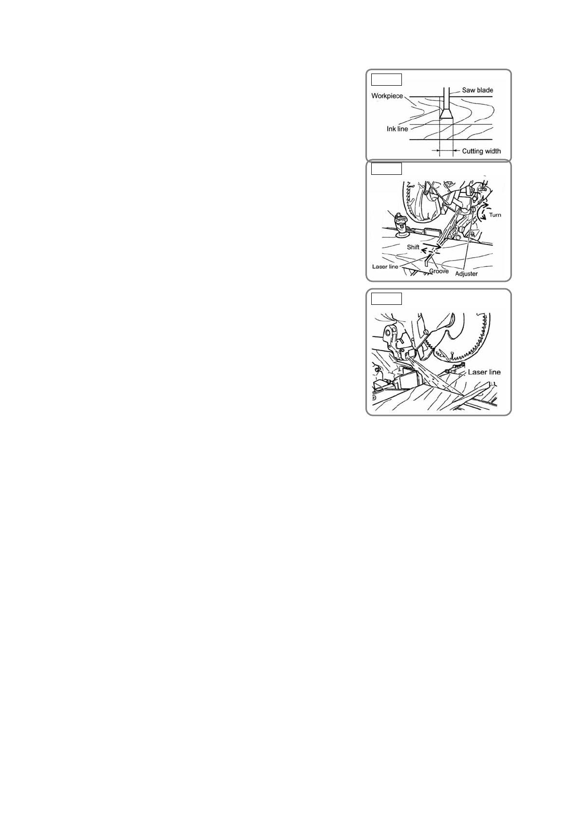
First, make a right-angle ink line on the workpiece that is about
20 mm (25/32") in height and 150 mm (5-29/32") in width.
To cut the right side of the ink line with the saw blade as shown
in Fig. 18, align the left side of the saw blade with the ink line
on the workpiece and make a groove of about 5 mm deep on
the workpiece to the middle. Hold the grooved workpiece by
the vise as it is and do not move it. (For grooving work, refer to
the Instruction Manual "Groove cutting procedures.")
Light up the laser marker. Turn the adjuster to align the laser
line with the ink line. (Turning the adjuster clockwise will shift
the laser line position to the right and turning counterclockwise
will shift to the left.) (Fig. 19)
Thus the cutting position matches the laser line position. Align
the ink line on the workpiece with the laser line. When aligning
the ink line, slide the workpiece little by little and secure it by
vise at a position where the laser line overlaps with the ink line
(Fig. 20). Work on the grooving again and check the position
of the laser line. When the ink line and the laser line are
overlapped, the strength and weakness of light will change,
resulting in a stable cutting operation because you can easily
discern the conformity of lines. This ensures the minimum
cutting errors.
WARNING:
Make sure before plugging the power plug into the receptacle that the main body and the laser
marker are turned off.
Exercise utmost caution in handling a switch trigger for the position adjustment of the laser line,
as the power plug is plugged into the receptacle during operation. If the switch trigger is pulled
inadvertently, the saw blade can rotate and result in unexpected accidents.
Do not remove the laser marker to be used for other purposes.
CAUTION:
Laser radiation - Do not stare into beam.
Laser radiation on work table - Do not stare into beam.
If your eye is exposed directly to the laser beam, it can be hurt.
Do not dismantle it.
Do not give strong impact to the laser marker (main body of tool); otherwise, the position of a
laser line can go out of order, resulting in the damage of the laser marker as well as a shortened
service life.
Keep the laser marker lit only during a cutting operation. Prolonged lighting of the laser marker
can result in a shortened service life.
NOTE:
Perform cutting by overlapping the ink line with the laser line. When the ink line and the laser line
are overlapped, the strength and weakness of light will change, resulting in a stable cutting operation
because you can easily discern the conformity of lines. This ensures the minimum cutting errors.
In outdoor or near-the-window operations, it may become difficult to observe the laser line due to
the sunlight. Under such circumstances, move to a place that is not directly under the sunlight
and engage in the operation.
Do not tug on the cord behind the motor head or hook your finger, wood and the like around it;
otherwise, the cord may come off and the laser marker may not be lit up.
Instruct the above precautions on the laser marker to the customers.
Fig. 19
Fig. 20
Fig. 18
Vise
assembly
  • Page 1 1
  • Page 2 2
  • Page 3 3
  • Page 4 4
  • Page 5 5
  • Page 6 6
  • Page 7 7
  • Page 8 8
  • Page 9 9
  • Page 10 10
  • Page 11 11
  • Page 12 12
  • Page 13 13
  • Page 14 14
  • Page 15 15
  • Page 16 16
  • Page 17 17
  • Page 18 18
  • Page 19 19
  • Page 20 20
  • Page 21 21
  • Page 22 22
  • Page 23 23
  • Page 24 24
  • Page 25 25
  • Page 26 26
  • Page 27 27
  • Page 28 28
  • Page 29 29
  • Page 30 30
  • Page 31 31
  • Page 32 32
  • Page 33 33
  • Page 34 34
  • Page 35 35
  • Page 36 36
  • Page 37 37
  • Page 38 38
  • Page 39 39
  • Page 40 40
  • Page 41 41
  • Page 42 42
  • Page 43 43
  • Page 44 44
  • Page 45 45
  • Page 46 46
  • Page 47 47
  • Page 48 48
  • Page 49 49
  • Page 50 50
  • Page 51 51
  • Page 52 52
  • Page 53 53
  • Page 54 54
  • Page 55 55
  • Page 56 56
  • Page 57 57
  • Page 58 58
  • Page 59 59
  • Page 60 60
  • Page 61 61
  • Page 62 62
  • Page 63 63
  • Page 64 64
  • Page 65 65
  • Page 66 66
  • Page 67 67
  • Page 68 68

Hitachi C 8FSE User manual

Category
Mitre saws
Type
User manual
This manual is also suitable for

Ask a question and I''ll find the answer in the document

Finding information in a document is now easier with AI