
User’s Guide
AB1771-C
Network Master
(Version 5.21)
For
Allen-Bradley Series PLC-5 Programmable Controllers
(Date: 2004-11-18)

Copyright © 2004 EIM COMPANY, INC. • 13840 PIKE ROAD • MISSOURI CITY, TX. 77489
Page i
Controlinc 1771-C (Version 5.21) Network Master Users Guide (2004-11-18)
User’s Guide
Controlinc Network Master … AB1771-C (Version 5.21)
For
Allen-Bradley Series PLC-5 Programmable Controllers
Table of Contents
0. Quick Start Information...............................................................................1
1. Introduction...................................................................................................2
1.1. Overview of 1771-C System ................................................................................... 2
1.2. Overview of Changes in Version 5.21 ................................................................... 4
1.3. Reference Manuals ................................................................................................. 6
1.4. EIM Equipment Compatibility .............................................................................7
1.5. Firmware ................................................................................................................. 7
2. 1771-C Hardware..........................................................................................8
2.1. Hardware Setup ...................................................................................................... 8
2.2. LED Utilization ....................................................................................................... 9
2.2.1. Green (PTX & PTR) and Yellow (LED1 & LED2) LED Usage ............................... 9
2.2.2. Red “BTL” LED Usage......................................................................................... 11
3. Network Setup and Connecting to the NIU ..............................................12
3.1. Field Connections at the Actuator....................................................................... 14
3.1.1. Step 1. Plan the Network Topology ................................................................... 14
3.1.2. Step 2. Select Network Cable............................................................................ 14
3.1.3. Step 3. Route Cable away from Electrical Interference ..................................... 15
3.1.4. Step 4. Observe Polarity and Network Grounding ............................................. 15
3.1.5. Step 5. Wire Preparation and Connections........................................................15
3.1.6. Step 6. Test Network ......................................................................................... 15
3.2. Field Network Cable Connection to the NIU ..................................................... 16
3.3. Cable Connection Between the NIU and the Network Master ........................ 16
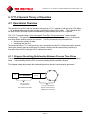
4. 1771-C General Theory of Operation .......................................................17
4.1. Operational Overview ..........................................................................................17
4.1.1. Diagram Describing Relationship Between Process Time Slices ........................ 17

Copyright © 2004 EIM COMPANY, INC. • 13840 PIKE ROAD • MISSOURI CITY, TX. 77489
Page ii
Controlinc 1771-C (Version 5.21) Network Master Users Guide (2004-11-18)
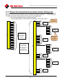
4.1.2. Diagram Describing Network Scanning & Actuator Writing Logic........................ 18
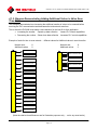
4.1.3. Diagram Demonstrating Adding Additional Valves in Valve Scan Time-Slice...... 19
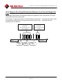
4.1.4. Diagram Describing Relationship Between Scan Period & Diagnostic Scan....... 20
4.1.5. 1771-C System Operations at Power Up............................................................. 21
4.2. Network Interface (Scan) Time-Slice (1771-C ↔ Network Communication) 22
4.2.1. Operation: Network Scanning to Gather Valve Actuator Data ............................ 22
4.2.2. Operation: The Network Communication Diagnostic Scan................................. 23
4.3. PLC Interface Time-Slice (1771-C ↔ PLC Communication).......................... 25
4.3.1. Operation: PLC (Write Data Tables To) or (Read Tables From) the 1771-C...... 27
4.3.2. Operation: PLC Commands to Write Data to the Actuators................................ 30
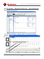
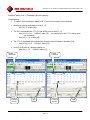
4.3.3. RLL Example … Manually Send New Table … Auto Read Response ................ 32
5. System Tables..............................................................................................33
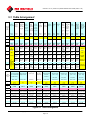
5.1. Table Arrangement...............................................................................................35
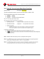
5.2. Standard Header Format (All Tables) … Words [0 3] ................................37
5.2.1. Word [0]: Table ID............................................................................................. 37
5.2.2. Word [1]: Read / Write Command Indicator ...................................................... 37
5.2.3. Word [2]: Reserved / Firmware ID..................................................................... 37
5.2.4. Word [3]: Emergency Shut Down (ESD) Command Word & Indication ............ 38
5.3. Table [0] … System Information Table.............................................................. 39
5.3.1. Table [0] Overview............................................................................................... 39
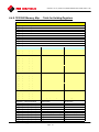
5.3.2. Table [0] Configuration Words … Words [4 17]................................................ 42
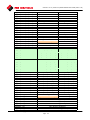
5.3.3. Table [0] Run-Time Information Words … Words [47 63] ................................ 47
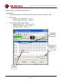
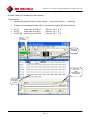
5.3.4. Table [0] … RSLOGIX-5 Examples ..................................................................... 48
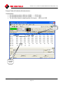
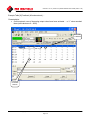
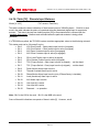
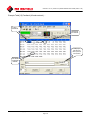
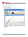
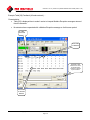
5.3.4.1. Example RSLOGIX-5 Screen: ..............................................................................48
5.3.4.2. Table [0] … The Configuration Values (RSLOGIX-5). .........................................49
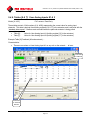
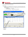
5.3.4.3. Table [0] … The Configuration Values – Writing Table [0] (RSLOGIX-5) ............50
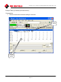
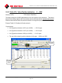
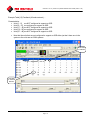
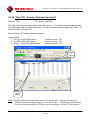
5.3.4.4. Table [0] … The Run-Time Feedback Values From 1771-C (RSLOGIX-5).........51
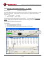
5.4. Tables [1 20] … Actuator Information Tables.............................................. 52
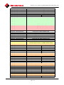
5.4.1. Table [1]: Communication Error Status............................................................... 52
5.4.2. Table [2]: Actuator Operational Status................................................................ 54
5.4.3. Table [3]: Discrete Control Mode (Open/Close/Stop) .........................................56
5.4.4. Table [4]: Valve Position Indication … 0 – 100.0% ............................................. 58
5.4.5. Table [5]: Valve Position Setpoint … 0 – 4095 ...................................................59
5.4.6. Tables [6 & 7]: User Analog Inputs #1 & 2.......................................................... 61
5.4.7. Table [8]: Analog Output #1................................................................................ 62
5.4.8. Tables [9 & 10]: Digital Input Accumulators (Totalizers) #1 & 2.......................... 64
5.4.9. Table [11]: Valve Position Indication … 0 – 4095 ............................................... 66
5.4.10. Table [12]: Discrete Input Statuses................................................................... 67
5.4.11. Table [13]: Solid State Relay (SSR) Configuration Table .................................69

Copyright © 2004 EIM COMPANY, INC. • 13840 PIKE ROAD • MISSOURI CITY, TX. 77489
Page iii
Controlinc 1771-C (Version 5.21) Network Master Users Guide (2004-11-18)
5.4.12. Table [14]: Additional Register Being Polled From Entire Network................... 71
5.4.13. Table [15]: Additional Block of Registers Being Polled From 1 Actuator........... 73
5.4.14. Tables [16 & 17]: Monitor & Control Discrete Digital Outputs ........................... 76
5.4.15. Table [18]: Actuator System Type ID................................................................ 80
5.4.16. Table [19]: Actuator Firmware Version ID......................................................... 82
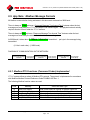
5.4.17. Table [20]: Modbus Exception Message Response..........................................83
5.4.18. Tables [21-24]: TEC2000 Status Inputs............................................................ 85
6. Application Notes ........................................................................................87
6.1. App Note: Performance Tuning ......................................................................... 87
6.1.1. General Practices to Ensure Better Performance................................................ 87
6.1.2. Reading Run-Time Information from Table [0]..................................................... 87
6.1.3. Loading Table [0] with Configuration Information ................................................ 88
6.1.4. Behavior if a Delay in Loading Table [0] Configuration Information ..................... 89
6.1.5. Using the “Scan Period” Value ............................................................................ 90
6.2. App Note: 1771-C Operation – Additional Detailed Information .................. 91
6.2.1. Determining & Exiting “Network Down” Condition ............................................... 91
6.2.2. Detailed Description of 1771-C Operation ........................................................... 92
6.2.3. Time Allocated Process Control (Allocated Time Slices)..................................... 93
6.2.4. Preferred Communication Port Operation............................................................ 95
6.2.5. Communication Failure Indications (Low-Level & High-Level)............................. 96
6.2.6. Bringing Units On-Line After a Power Cycle ........................................................ 99
6.2.7. Toggling the Preferred Port to Assist Diagnostics ............................................. 100
6.3. App Note: For Diagnostics - Know the Physical Network Wiring ............... 101
6.4. App Note: Memory Maps ................................................................................. 102
6.4.1. Specific Holding Registers Referenced by the Network Master......................... 102
6.4.2. Specific Coils & Inputs Referenced by the Network Master............................... 103
6.4.3. 320A Memory Map … Table for Coils & Inputs (Version 2.0) ............................ 104
6.4.4. 320A Memory Map … Addressable Holding Registers (Version 2.0) ................ 105
6.4.5. 320B Memory Map … Table for Coils & Inputs.................................................. 107
6.4.6. 320B Memory Map … Addressable Holding Registers...................................... 108
6.4.7. TEC2000 Memory Map … Table for Coils & Inputs........................................... 110
6.4.8. TEC2000 Memory Map … Table for Holding Registers..................................... 111
6.5. App Note: Modbus Message Formats.............................................................. 116
6.5.1. Modbus RTU Functions (Command Codes) Implemented ................................ 116
6.5.2. Modbus Function (Command) Code Descriptions ............................................. 117
6.5.2.1. Modbus Function Code 01 … Read Coil Status .................................................117
6.5.2.2. Modbus Function Code 03 … Read Holding Register........................................118
6.5.2.3. Modbus Function Code 05 … Set (Force) Single Coil........................................119
6.5.2.4. Modbus Function Code 06 … Set Single Register .............................................120
6.5.2.5. Modbus Function Code 15 (0x0F) … Set (Force) Multiple Coils ........................121

Copyright © 2004 EIM COMPANY, INC. • 13840 PIKE ROAD • MISSOURI CITY, TX. 77489
Page iv
Controlinc 1771-C (Version 5.21) Network Master Users Guide (2004-11-18)
6.5.3. Modbus Exception Messages Supported .......................................................... 122
6.6. App Note: Install the 1771-C Network Master Firmware............................. 123
6.6.1. Configure the Module for a Firmware Upload .................................................... 124
6.6.2. Upload the 1771-C Firmware............................................................................. 125
6.6.3. Reset the 1771-C Module for Normal Operations.............................................. 126

Copyright © 2004 EIM COMPANY, INC. • 13840 PIKE ROAD • MISSOURI CITY, TX. 77489
Page 1
Controlinc 1771-C (Version 5.21) Network Master Users Guide (2004-11-18)
0. Quick Start Information
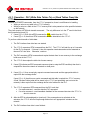
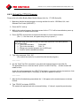
1. As a minimum, you should have access to the following reference documents:
• This manual (1771-C User’s Guide)
• Allen-Bradley 1771-DB, Series B Basic Module User's Manual
Catalog No. 1771-DB, Series B, Publication No. 1771-6.5.113
• EIM Controlinc 320A Quick Startup Guide, Rev. F or later
• EIM Controlinc 320B Quick Startup Guide, Rev. A or later
2. Refer to Section 2 of this manual on how the jumpers should be set on the DB module.
3. The 1771-C module comes from EIM pre-programmed with the network master program in it. However, if
for some reason the module needs to be flashed again (ex: a field upgrade) then refer to Section 5 on
installing the firmware in the module.
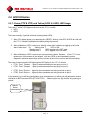
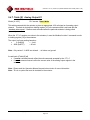
Note: Remember, you will need to connect a serial cable between the 1771-C and the computer. The
correct cable is a Null Modem Cable
connected between the PRT1 port (bottom DB25
connector on the module) and the serial communications port on the computer used for the
upload.
4. Ensure the PLC rack power is turned off.
Install the module in the correct slot in the PLC rack. Connect all cables and power the system up.
5. The PLC-RLL will start interfacing with the 1771-C after the 1771-C performs initial scans of the network
on power up.
NOTES: To ensure optimal performance, some things the PLC should do …
1. Ensure table [0] is set correctly and repeated in a timely manner. Allow for frequent table [0] read backs.
2. Restrict the rate of data writes to the actuators … only write as fast as required to adequately control the
valve.
(cuts down on the interruptions to scanning the network … gathering data)
3. Expedite responses to BTW/BTR requests made by the 1771-C. Delaying them can slow 1771-C
operations.
4. Only activate writing to or reading from tables if actually in use (or when needed).
(ex: do not write to the analog output table if analog outputs are not used)
(ex: do not read totalizer data if its not being used)
(ex: only poll for “static” [non-changing] data one time and stop)
(prevents unnecessary delays to gathering the more important data from the network)
Remember:
The 1771-C uses explicit read/write commanding of the tables such that if word [1] in any table is
zero (0) then it is a table read request by the PLC. Otherwise, the command is a table write
command.

Copyright © 2004 EIM COMPANY, INC. • 13840 PIKE ROAD • MISSOURI CITY, TX. 77489
Page 2
Controlinc 1771-C (Version 5.21) Network Master Users Guide (2004-11-18)
1. Introduction
1.1. Overview of 1771-C System
This document is intended for end users as a Guide in applying an EIM AB
1771-C Network Master.
The software that enables network operation is called a communication
driver. It is used in conjunction with an Allen-Bradley 1771-DB Series B
module thereby creating the 1771-C network master module. The 1771-C
allows an AB PLC-5 controller to acquire data from and send information to
an EIM Controlinc Actuator Network.
Other than changes to tables [11 & 12], version 5.21 is fully backwards
compatible with version 5.03.
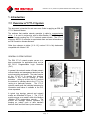
GENERAL SYSTEM PURPOSE:
The EIM 1771-C network master serves as a
data concentrator for applications that use an
AB PLC-5 Programmable Logic Controller
(PLC).
In general, the network master off-loads network
communication and management tasks from the
actual controlling equipment. The main function
of the 1771-C is to provide the interface
between a PLC and its network of valve
actuators. Acting as a Host, the PLC controls
the network by sending data to the 1771-C for
routing to a particular actuator. The 1771-C
network master polls the individual actuators for
information and makes it available to the PLC
when requested.
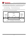
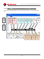
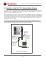
A typical ring topology network and network
master are illustrated in Figure 1. The 1771-C
module serves as a master within this Modbus
(Modbus RTU) master/slave network. The
module will manage network operation by
keeping an orderly cycle of data transfers
between itself and each slave (valve actuator).

Copyright © 2004 EIM COMPANY, INC. • 13840 PIKE ROAD • MISSOURI CITY, TX. 77489
Page 3
Controlinc 1771-C (Version 5.21) Network Master Users Guide (2004-11-18)
The 1771-C master will handle network communication, error detection, alarming, and network
recovery.
Other features include:
• Reporting of inaccessible actuators
• Reporting of network faults
• Emergency shutdown broadcasting
• Minimal Interfacing with the Relay Ladder Logic (RLL) program in the PLC CPU module
Each 1771-C module can support a single network of up to 60 valve actuators. Multiple modules can
be installed in a PLC-5 system rack to provide support for multiple networks (up to 60 actuators each).
Note 1: It is important to note that the 1771-C Network Master may be used in any slot in the 1771
rack, not just slot 0 next to the PLC-5 CPU.
It may also be located in remote 1771 racks.

Copyright © 2004 EIM COMPANY, INC. • 13840 PIKE ROAD • MISSOURI CITY, TX. 77489
Page 4
Controlinc 1771-C (Version 5.21) Network Master Users Guide (2004-11-18)
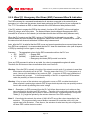
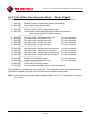
1.2. Overview of Changes in Version 5.21
Any later releases of this document for this version of the product (5.21) are to only correct entries in
this document … primarily grammatical or “typos” that are discovered in the future. Major ideas will be
documented with a separate “line entry”.
Major document changes:
1. This document: 2004-11-18
Previous document: 2004-08-17
Major Change: Memory Maps adjusted.
2. New document: 2004-08-17
Previous document: 2004-08-06
Major Changes: Memory Maps adjusted and this section added.
5.20 5.21
The following list identifies the most significant functional changes between version 5.20 and 5.21.
1. Table [17] was changed from read-only to read-write to allow an end user to clear it.
5.03 5.20
The following list identifies most significant functional changes between version 5.03 and 5.20.
1. The previous firmware release: version 5.03.
2. The number of tables increased …
• Version 5.03 … tables [0 - 13]
• Version 5.20 … tables [0 - 24]
3. Table [11] has a different function …
• Version 5.03 … indicate the status of digital input #1.
• Version 5.20 … indicate the valve’s current position in 0-4095 increments … register
[14].
4. Table [12] has a different function …
• Version 5.03 … indicate the status of digital input #2.
• Version 5.20 … indicate the status of all the actuator’s discrete inputs … register [05].
5. Additional system configuration words in table [0] …
• Version 5.03 … words [4 - 7]
• Version 5.20 … words [4 – 17]

Copyright © 2004 EIM COMPANY, INC. • 13840 PIKE ROAD • MISSOURI CITY, TX. 77489
Page 5
Controlinc 1771-C (Version 5.21) Network Master Users Guide (2004-11-18)
6. Run-Time data words in table [0] …
• Version 5.03 … words [49 – 63]
• Version 5.20 … words [47 – 63]
7. System Diagnostic Scan …
• Tests both ports … Identifies node system type … Table [18]
• Only one port … Identifies firmware Version ID … Table [19]
Gathers standard scan data.
8. Faster “full network response on power up” if power cycled on entire network.
9. Implemented Scan Period Counter (Accumulator) in table [0] … words [47 & 48] and the ability
for the operator to reset the counter using table [0] … words [15 & 16].
10. Separated communication errors such that if the error is due to the actuator (slave) responding
with a Modbus exception code (the low level communication was ok … however, the actuator
rejected it with an exception), the 1771-C now …
- does NOT report this as a communication error … table [1].
- records the exception code and error code sent by the actuator … table [20].
- clears the exception code on the next diagnostic scan.
11. Compatibility with multiple EIM equipment types (320A, 320B, TEC2000).
• Types are identified in table [18]
• 320A & 320B Firmware version ID is identified in table [19]
• 1771-C will check & test for SSR bit only if a 320A node.
12. User Configurable “Additional Message Response Delay Time
” …
• Configure … table [0] … word [8]
13. User Configurable “Poll Specific Register From All Nodes on Network
” …
• Configure … table [0] … words [9 & 10]
• The response is in table [14].
14. User Configurable “Poll Block of Registers From a Specific Node on the Network
” …
• Configure … table [0] … words [11 - 14]
• The response is in table [15].
15. User Configurable “Control Discrete Digital Outputs
…
• Configure … table [16]
• Monitoring the status of the outputs is in table [17].
16. User Configurable “Poll TEC2000 Inputs … registers [1000-1003]
” …
• Configure … table [0] … word [17]
• Response … tables [21-24]

Copyright © 2004 EIM COMPANY, INC. • 13840 PIKE ROAD • MISSOURI CITY, TX. 77489
Page 6
Controlinc 1771-C (Version 5.21) Network Master Users Guide (2004-11-18)
1.3. Reference Manuals
• Allen-Bradley 1771-DB, Series B Basic Module User's Manual
Catalog No. 1771-DB, Series B, Publication No. 1771-6.5.113
This manual is required for proper uploading of this driver into the hardware. It includes
specific information on Call Routines and handling block transfers instructions from the Basic
Module to the PLC-5 back plane.
• EIM … Controlinc 320A Quick Startup Guide, Rev. F or later
Publication No. ECL-4004-0102
This manual is used for specific information on the Controlinc 320A Controller card located in
the valve actuator. This includes networking, setup and available options.
• EIM … Controlinc 320B Quick Startup Guide
Publication No. ECL-4005-0404
This manual is used for specific information on the Controlinc 320B Controller card located in
the valve actuator. This includes networking, setup and available options.
• EIM … TEC2000 “Document … TBD”
Publication No. ?????????
At the time of this printing, this TEC2000 publication had not been made available.
• Other Allen-Bradley manuals specific to the PLC-5 being applied. These may be required to
implement the necessary Relay Ladder Logic (RLL) for application of the driver. For instance,
this may include:
o Allen Bradley PLC-5 Programmable Controllers Instruction Set Reference,
Publication 1785-6.1
This reference includes information in Chapter 15 on the AB Block Transfer
Instructions, Block Transfer Write and Block Transfer Read.

Copyright © 2004 EIM COMPANY, INC. • 13840 PIKE ROAD • MISSOURI CITY, TX. 77489
Page 7
Controlinc 1771-C (Version 5.21) Network Master Users Guide (2004-11-18)
1.4. EIM Equipment Compatibility
The 1771-C is compatible with the following EIM equipment:
• 320A … version 1.17 and later.
• 320B … all
• TEC2000 … all
Other points:
• The 1771-C derives the system type of each actuator during the diagnostic scan and stores the
results in table [18].
• The 1771-C derives the firmware Version ID for the 320A & 320B systems during the diagnostic
scan and stores the results in table [19].
• Since the TEC2000 system has several micro-controllers with firmware, a special request must
be made to them to derive the firmware version ID for each controller in the unit.
• The SSR bit is only checked and set on 320A actuators.
Note: For maximum compatibility with the TEC2000 systems, you should enable monitoring the
TEC2000 Status Inputs (tables [21-24]). This way, you can ensure you have all critical status
information for any TEC2000 system on the network. For more information, refer to the
section on Tables [21-24].
Note: This document references the addressable memory ranges (“Memory Maps”) of several EIM
actuators (ex: M2CP–320B, TEC2000). This is only for the reader’s convenience. The
specific details in the memory maps are only correct as of the date this manual was published.
Therefore, to ensure you have the most current memory information, please refer to the
technical information for that particular actuator.
1.5. Firmware
The firmware is a “driver program” which is a compiled application program (not an interpreted one). It
is loaded and stored in the module's 32K EEPROM (A-B P/N 1771-DBMEM2). The user is required to
provide configuration information from the PLC Relay Ladder Logic (RLL) for each specific application
(the RLL must load table [0] with appropriate configuration information).

Copyright © 2004 EIM COMPANY, INC. • 13840 PIKE ROAD • MISSOURI CITY, TX. 77489
Page 8
Controlinc 1771-C (Version 5.21) Network Master Users Guide (2004-11-18)
2. 1771-C Hardware
2.1. Hardware Setup
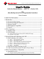
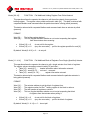
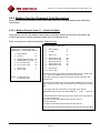
Refer to Chapter 1 of the 1771-DB manual. The following hardware jumper settings are required. If the
1771-DB module was supplied by EIM, jumpers are already set and no other settings are required.
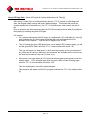
For the 1771-C to run, the jumper
settings on the DB module should be set
as follows:
• JW1 - enable watchdog timer
• JW2 - 32K EEPROM
• JW3 - turbo
• JW4 - PRT1 = ASCII
- PRT2 = ASCII
- DH485 = PGM
• JW5 - 8-point mode
• JW6 - 9600 bit/s
• JW7 - enable battery
• JW8 - RS232
• JW9 - RS232
This jumper configuration is normally
performed by EIM before shipping the
1771-C.
(Jumper settings are screened on the
side of the 1771-DB module)
Figure 2-1 – Hardware jumpers of the 1771-DB

Copyright © 2004 EIM COMPANY, INC. • 13840 PIKE ROAD • MISSOURI CITY, TX. 77489
Page 9
Controlinc 1771-C (Version 5.21) Network Master Users Guide (2004-11-18)
2.2. LED Utilization
2.2.1. Green (PTX & PTR) and Yellow (LED1 & LED2) LED Usage
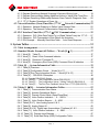
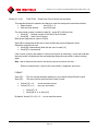
There are 2 “Yellow” LED lights on the front of the 1771-C module
• LED1.
• LED2.
There are currently 3 general functions operating these LEDs:
1. After CPU restart (power up or pressing the <RESET> button), both LED1 & LED2 are ON until
the 1771-C finishes initialization and starts polling the network.
2. After initialization, LED1 is used as a “starting a new scan” indicator by toggling on/off at the
start of each scan. Ex: Starting scan 1: LED1 is ON.
Starting scan 2: LED1 toggles to the OFF state.
Starting scan 3: LED1 toggles to the ON state.
3. After initialization, LED2 is used as an “entire network is down” indicator. If the 1771-C ever
detects zero (0) actuators on the network, it will turn LED2 on and immediately enter a
diagnostic scan and remain there until an actuator is found to be on-line and communicating.
There are 4 communication LED lights (green LED lights) on the 1771-C module:
• PT1X: Port 1 Transmit … lights up when transmissions are going out port 1.
• PT2X: Port 2 Transmit … lights up when transmissions are going out port 2.
• PT1R: Port 1 Receive … lights up when characters are being received on port 1.
• PT2R: Port 2 Receive … lights up when characters are being received on port 2.
If the network is in a valid ring configuration, then a transmission on either port will generate a receive
indication on BOTH receive LEDs (PT1R & PT2R). Observing this is a sign that the ring topology is
correct.
Manual
Reset
button/switch

Copyright © 2004 EIM COMPANY, INC. • 13840 PIKE ROAD • MISSOURI CITY, TX. 77489
Page 10
Controlinc 1771-C (Version 5.21) Network Master Users Guide (2004-11-18)
Green LED App Note:
Green LED Lights & System Initialization with Table [0]
After startup, if table [0] is not initialized shortly after the 1771-C finishes its initial diagnostic
scan, the program starts running with factory default settings. This means that unless the
network actually has 60 actuators on it, the 1771-C will believe the “other valves” are just off
line.
Plus, an operator can often determine when the PLC-RLL actually writes to table [0] (configures
the system) by watching the green LED lights.
For instance …
• On a network that actually has 25 valves on it (addressed 1-25), until table [0] – word [4]
gets initialized with 25, the program thinks that there are still supposed to be 60
actuators on the network … only the last 35 happen to be “off line”.
• Then (if viewing the green LED lights) when a scan starts (LED1 changes state), you will
see the green LEDs “flash” while the 1771-C communicates with valves 1-25.
Then you will observe a “dead space” in time when the program is trying to determine if
any of the final 35 valves “it believes to be connected” are available (and of course none
are because the network only has 25 valves on it).
• As soon as a new scan starts (all “60” valves have been checked and ready to scan the
network again … LED1 changes state) then the green LEDs will start flickering again
while the 1771-C communicates with valves 1-25.
Then the “dead space” time will be observed again.
This sequence will repeat until the PLC program initializes the 1771-C by writing to table
[0].

Copyright © 2004 EIM COMPANY, INC. • 13840 PIKE ROAD • MISSOURI CITY, TX. 77489
Page 11
Controlinc 1771-C (Version 5.21) Network Master Users Guide (2004-11-18)
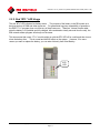
2.2.2. Red “BTL” LED Usage
The red “BTL” LED indicates low battery status. The purpose of the battery in the DB module is to
back up portions of RAM and other resources. For guaranteed long-term repeatability of operations,
the EIM 1771-C program does not utilize any of these resources. Therefore, it doesn’t matter what
state the battery is in (installed and fully charged, inline and dead or totally removed from the unit), the
EIM network master program will always run the same.
This also means that a new 1771-C module might run with the BTL LED off for a while and then turn on
when the battery dies. This is normal and has NO effect on the system. However, if for some
reason you want to replace the battery, you can order it directly from Allen-Bradley.
“BTL”
LED

Copyright © 2004 EIM COMPANY, INC. • 13840 PIKE ROAD • MISSOURI CITY, TX. 77489
Page 12
Controlinc 1771-C (Version 5.21) Network Master Users Guide (2004-11-18)
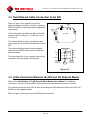
3. Network Setup and Connecting to the NIU
In general, the EIM NIU (“Network Interface Unit”) is a “beefed up” and configurable RS232 RS485
converter.
The ports on the 1771-C, Port1 (PRT1)
and Port 2 (PRT2), are configured for
serial communication using RS-232.
The network communication parameters
are pre-configured and fixed at 9600 baud
– 8 bit – no parity – 1 stop bit.
The NIU isolates and protects the 1771-C
and the PLC from the network and is
powered by its own 120 AC circuit. Its
primary function is to convert RS232
communications to RS485
communications. The RS485 connection
then communicates to a ring or ring
network.
Note: To help with isolation, there are
two (2) entirely separate boards in the
NIU. However, because of this, there are
two (2) 120 VAC connections to the NIU.
Ensure that both are connected (you can
jumper the circuits together).
The Controlinc network is connected to
the 1771-C module via the Network
Interface Unit (NIU). It doesn’t matter if
you connect:
• Port 2 (PRT2) (top DB25 connector): connects to the NIU at the port labeled “HOST A”.
• Port 1 (PRT1) (bottom DB25 connector): connects to the NIU at the port labeled “HOST B”.
or
• Port 1 (PRT1) (bottom DB25 connector): connects to the NIU at the port labeled “HOST A”.
• Port 2 (PRT2) (top DB25 connector): connects to the NIU at the port labeled “HOST B”.
However, it is recommended that you remain consistent.
NOTE: You can always connect a PC to the network at the NIU if you …
• Disconnect the cable connecting the 1771-C and NIU.
• Connect the PC using a (serial cable + NULL modem) to the DB9 connector on the NIU.

Copyright © 2004 EIM COMPANY, INC. • 13840 PIKE ROAD • MISSOURI CITY, TX. 77489
Page 13
Controlinc 1771-C (Version 5.21) Network Master Users Guide (2004-11-18)
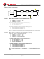
A typical E>Net network connection format is in a ring …
• It starts from Port 1 (PRT1) (the top DB25 connector) on the 1771-C as RS232 and connects to
the NIU at the port labeled “Host A”.
• It exits the NIU at the port labeled “Port A” as an RS485 circuit and proceeds to the first valve
actuator, normally addressed as #1, in port A.
• It exits the actuator from Port B and proceeds to the port A next actuator (address #2) and on
until the last actuator on the network is connected.
• The RS485 network then exits port B on the last actuator returns to the NIU at the port labeled
“Port B”.
• The network connection is then transformed back to an RS232 format and exits the NIU via the
port labeled “Host B”
• It connects to the 1771-C via port2 (PRT2) (the bottom DB25 connector).

Copyright © 2004 EIM COMPANY, INC. • 13840 PIKE ROAD • MISSOURI CITY, TX. 77489
Page 14
Controlinc 1771-C (Version 5.21) Network Master Users Guide (2004-11-18)
3.1. Field Connections at the Actuator
Communication connections and wiring are important for the network and the master.
(The following information was primarily derived from the Controlinc Quick Startup Guide)
3.1.1. Step 1. Plan the Network Topology
Before connecting actuators, the entire network layout should be planned. Topologies may be bus,
redundant bus, E>Net, redundant E>Net, E>Net ring, and redundant E>Net rings. Planning should
include node addressing, wire routing, terminations, and grounding.
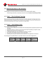
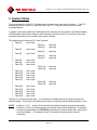
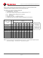
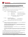
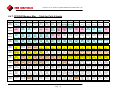
3.1.2. Step 2. Select Network Cable
Ensure correct cable is being used.
• Networks require twisted pair and shielded cable with characteristic impedance between 50 and
120 Ohms.
• Capacitance between conductors must be less that 30 pF/Ft (98 pF/M); 10-15pF/Ft is ideal.
• Shielding maybe aluminum foil with drain wire.
• If cable has multiple pairs, then individual pair shielding is required.
• Only cables with stranded conductors are recommended.
• Insulating and outer jacket materials must be selected for the application environment.
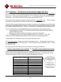
The following are acceptable Belden or equivalent cables for most network applications.
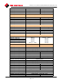
AWG 20 18 16 14
Beldon # 8762 8760 8719 8720
Rating 12.8 Pf/fT 12.8 Pf/fT 12.8 Pf/fT 12.8 Pf/fT

Copyright © 2004 EIM COMPANY, INC. • 13840 PIKE ROAD • MISSOURI CITY, TX. 77489
Page 15
Controlinc 1771-C (Version 5.21) Network Master Users Guide (2004-11-18)
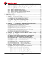
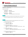
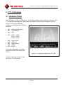
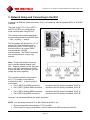
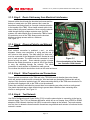
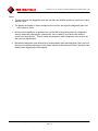
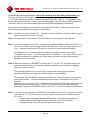
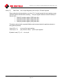
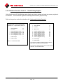
3.1.3. Step 3. Route Cable away from Electrical Interference
Network cables should enter the electrical enclosures and the
bottom or lowest point (on 320A systems, this is near the
transformer end and normally in a counter clockwise direction
to the topside of the TBM). Never install network cable in the
same conduit with power conductors. Never route the network
cable through the high voltage contactor area. On 320A
systems, the cable should never lie across the TBM or hinder
the protective cover of the TBM. Always use the shortest
distance and keep access cable to a minimum.
See Figure 3-1
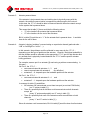
3.1.4. Step 4. Observe Polarity and Network
Grounding
Each network connection is polarized + and - on wiring
diagrams. Always use consistency in wiring and the use of
wire colors to track polarity. The cable shield (or “drain wire”)
must be connected to the designated “shield” terminal at each
port of each actuator. The shield must be connected to earth
ground at only one point. Some networks require a jumper
between the shield connections on ports A & B of the actuator
to carry the shielding through the network. The shield
connection of each actuator is isolated from earth ground.
Do not allow the shield to touch other circuits or the metal enclosure.
3.1.5. Step 5. Wire Preparation and Connections
Screw terminal connections on the TBM and in the TEC2000 terminal chamber have wire clamps,
which will accept conductors with out terminals. Wire terminals may be applied if desired but are not
required. Strip conductor insulation back 3/8” when connecting directly to the TBM screw terminals. Do
not allow wire clippings to fall on the TBM or into the enclosure.
Protect the conductors and shield to prevent them from contacting any other circuits or earth ground.
Use plastic electrical tape or heat shrink tubing to prevent bare conductors from contacting other
circuits or earth ground. See Figure 3-1
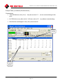
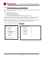
3.1.6. Step 6. Test Network
Use EIM’s Configuration and Control Utility (CCU) to test the network prior to connecting to the host or
network master. The CCU is a Windows application, which will run on a laptop. Use a RS232 to RS485
adapter or EIM’s Network Interface Unit (NIU) to connect the laptop to the network. Test each actuator,
one at a time, to determine that all network connections are good and each actuator is functional via the
network in remote.
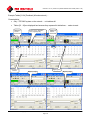
Figure 4-1
Correct termination of the Network
to a Controlinc 320A Actuator
Figure 3-1
Correct termination of the Network
to a Controlinc 320A Actuator
Page is loading ...
Page is loading ...
Page is loading ...
Page is loading ...
Page is loading ...
Page is loading ...
Page is loading ...
Page is loading ...
Page is loading ...
Page is loading ...
Page is loading ...
Page is loading ...
Page is loading ...
Page is loading ...
Page is loading ...
Page is loading ...
Page is loading ...
Page is loading ...
Page is loading ...
Page is loading ...
Page is loading ...
Page is loading ...
Page is loading ...
Page is loading ...
Page is loading ...
Page is loading ...
Page is loading ...
Page is loading ...
Page is loading ...
Page is loading ...
Page is loading ...
Page is loading ...
Page is loading ...
Page is loading ...
Page is loading ...
Page is loading ...
Page is loading ...
Page is loading ...
Page is loading ...
Page is loading ...
Page is loading ...
Page is loading ...
Page is loading ...
Page is loading ...
Page is loading ...
Page is loading ...
Page is loading ...
Page is loading ...
Page is loading ...
Page is loading ...
Page is loading ...
Page is loading ...
Page is loading ...
Page is loading ...
Page is loading ...
Page is loading ...
Page is loading ...
Page is loading ...
Page is loading ...
Page is loading ...
Page is loading ...
Page is loading ...
Page is loading ...
Page is loading ...
Page is loading ...
Page is loading ...
Page is loading ...
Page is loading ...
Page is loading ...
Page is loading ...
Page is loading ...
Page is loading ...
Page is loading ...
Page is loading ...
Page is loading ...
Page is loading ...
Page is loading ...
Page is loading ...
Page is loading ...
Page is loading ...
Page is loading ...
Page is loading ...
Page is loading ...
Page is loading ...
Page is loading ...
Page is loading ...
Page is loading ...
Page is loading ...
Page is loading ...
Page is loading ...
Page is loading ...
Page is loading ...
Page is loading ...
Page is loading ...
Page is loading ...
Page is loading ...
Page is loading ...
Page is loading ...
Page is loading ...
Page is loading ...
Page is loading ...
Page is loading ...
Page is loading ...
Page is loading ...
Page is loading ...
Page is loading ...
Page is loading ...
Page is loading ...
Page is loading ...
Page is loading ...
Page is loading ...
-
 1
1
-
 2
2
-
 3
3
-
 4
4
-
 5
5
-
 6
6
-
 7
7
-
 8
8
-
 9
9
-
 10
10
-
 11
11
-
 12
12
-
 13
13
-
 14
14
-
 15
15
-
 16
16
-
 17
17
-
 18
18
-
 19
19
-
 20
20
-
 21
21
-
 22
22
-
 23
23
-
 24
24
-
 25
25
-
 26
26
-
 27
27
-
 28
28
-
 29
29
-
 30
30
-
 31
31
-
 32
32
-
 33
33
-
 34
34
-
 35
35
-
 36
36
-
 37
37
-
 38
38
-
 39
39
-
 40
40
-
 41
41
-
 42
42
-
 43
43
-
 44
44
-
 45
45
-
 46
46
-
 47
47
-
 48
48
-
 49
49
-
 50
50
-
 51
51
-
 52
52
-
 53
53
-
 54
54
-
 55
55
-
 56
56
-
 57
57
-
 58
58
-
 59
59
-
 60
60
-
 61
61
-
 62
62
-
 63
63
-
 64
64
-
 65
65
-
 66
66
-
 67
67
-
 68
68
-
 69
69
-
 70
70
-
 71
71
-
 72
72
-
 73
73
-
 74
74
-
 75
75
-
 76
76
-
 77
77
-
 78
78
-
 79
79
-
 80
80
-
 81
81
-
 82
82
-
 83
83
-
 84
84
-
 85
85
-
 86
86
-
 87
87
-
 88
88
-
 89
89
-
 90
90
-
 91
91
-
 92
92
-
 93
93
-
 94
94
-
 95
95
-
 96
96
-
 97
97
-
 98
98
-
 99
99
-
 100
100
-
 101
101
-
 102
102
-
 103
103
-
 104
104
-
 105
105
-
 106
106
-
 107
107
-
 108
108
-
 109
109
-
 110
110
-
 111
111
-
 112
112
-
 113
113
-
 114
114
-
 115
115
-
 116
116
-
 117
117
-
 118
118
-
 119
119
-
 120
120
-
 121
121
-
 122
122
-
 123
123
-
 124
124
-
 125
125
-
 126
126
-
 127
127
-
 128
128
-
 129
129
-
 130
130
-
 131
131


Ask a question and I''ll find the answer in the document
Finding information in a document is now easier with AI
Related papers
-
Emerson Network Master User guide
-
Baldor 15H SERIES 15H User manual
-
EIM HQ-008 to 300 Series Owner's manual
-
-
-
-
-
-
-
Other documents
-
ZAPTEC Power Line Communication Installation guide
-
Endres+Hauser BA ORSG35 Operating instructions
-
Bernard Controls Fielbus Solution MODBUS FOR INTELLI+ Installation & Operation Manual
-
 Aspar MOD-1AO 1 Analog Universal Output User manual
-
 NIU KQi2 Operating instructions
-
-
Hardy HI1771-WS User manual
-
Allen-Bradley 1771-ODD Installation guide
-
-
Genius AiBOT RC 320A User manual

