Page is loading ...

1
IMPORTANT:
Go to www.extron.com for the complete
user guide, installation instructions, and
specifications before connecting the
product to the power source.
DVC RGB-HD A • Setup Guide
The Extron DVC RGB-HD A is a one VGA input, one HDMI output converter that digitizes analog RGBHV video to HDMI, with
analog stereo audio embedding. It accepts resolutions from 640x480 up to 1080p @ 60 Hz and 1920x1200 @ 60 Hz with reduced
blanking. A USB port allows for system conguration and rmware updates using Extron Simple Instruction Set (SIS) commands
or PCS Product Conguration Software. The DVC RGB-HD A allows the adaptation or integration of legacy VGA products into
an all-digital audio-video system. It features a dual-purpose signal presence and power LED for troubleshooting, as well as eld
upgradable rmware.
Installation
ATTENTION:
• Installation and service must be performed by authorized personnel only.
• L’installation et l’entretien doivent être effectués par le personnel autorisé uniquement.
NOTE: For full installation, configuration, connector wiring, and SIS commands, see the DVC RGB-HD 4K A User Guide,
available at www.extron.com.
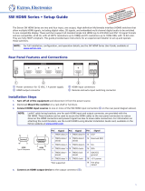
Front Panel
INPUT
DVC RGB-HD A
AA
BB
CC
Figure 1. DVC RGB-HD A Front Panel
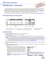
Rear Panel
OUTPUT
POWER
12V
0.2A MAX
CONFIG
CC
A
A
BB
Figure 2. DVC RGB-HD A Rear Panel
A
Power and signal status LED — This bi-color LED
lights as follows:
• Amber while the unit is powered by a 12 VDC
external power supply
• Green when the DVC detects horizontal sync on the
input
B
VGA input — Connect an RGBHV input, such as a
computer, to this 15-pin VGA connector (a male-to-male,
15-pin mini VGA cable is provided for this connection).
The DVC digitizes and converts the RGB input signal to
DVI or HDMI format.
C
Audio input — Connect an analog audio input to
this 3.5 mm TRS jack. The analog audio input can be
embedded onto the TMDS output. TMDS output with
embedded analog audio (HDMI RGB Full 4:4:4) is default.
A
Power connector — Connect a 12 VDC power supply
(not included) between this 2-pole, 3.5 mm captive screw
connector and a 100 to 240 VAC, 50 Hz or 60 Hz power
source.
B
HDMI output connector — Connect an HDMI sink to this
female HDMI connector.
• No input signal — When there is no input signal
present, this connector does not output TMDS data
or clock activity.
• Output 5 V mode — This mode is congurable via
SIS commands (see the DVC RGB-HD A User Guide
for information on these commands). Select either of
the following for the 5 V mode:
• Always enabled (default) — The 5 V pin is
always active, regardless of the input status. This
enables the unit to detect hot-plug assertion and
read the EDID from a connected sink.
• Auto — 5 V output is active only when a
source is connected to the input. If no source is
connected the 5 V output is disabled.
C
Config port — Use a USB A-to-mini B cable to connect
this port to a USB port on the computer.
#8 Screw
(2) Places
Each Side
MBU 125 Mounting Bracket
Mounting the DVC RGB-HD under Furniture

2
68-2898-50 Rev. A
07 16
Extron Headquarters
+800.633.9876 Inside USA/Canada Only
Extron USA - West Extron USA - East
+1.714.491.1500 +1.919.850.1000
+1.714.491.1517 FAX +1.919.850.1001 FAX
Extron Europe
+800.3987.6673
Inside Europe Only
+31.33.453.4040
+31.33.453.4050 FAX
Extron Asia
+65.6383.4400
+65.6383.4664 FAX
Extron Japan
+81.3.3511.7655
+81.3.3511.7656 FAX
Extron China
+86.21.3760.1568
+86.21.3760.1566 FAX
Extron Middle East
+971.4.299.1800
+971.4.299.1880 FAX
Extron Australia
+61.8.8351.2188
+61.8.8351.2511 FAX
Extron India
1800.3070.3777
(Inside India Only)
+91.80.3055.3777
+91.80.3055.3737 FAX
© 2016 Extron Electronics All rights reserved. All trademarks mentioned are the property of their respective owners. www.extron.com
Installation Overview
1. Disconnect power — Turn off or disconnect all equipment power sources.
2. (Optional) Mount the unit — Mount the DVC RGB-HD A either in a rack using a shelf mounting bracket kit (see the
instructions provided with the kit) or under furniture using a furniture mounting kit (see Mounting the DVC RGB-HD under
Furniture on page 1). Extron mounting kits are available at www.extron.com.
3. Connect the input — Connect an RGBHV source to the front panel VGA input connector (see figure 1,
B
, on the previous
page).
4. (Optional) Connect the audio input — Connect analog audio to the 3.5 mm TRS jack on the front panel (
C
).
5. Connect the digital output — Connect a digital sink to the rear panel HDMI output connector (see figure 2,
B
, on the
previous page).
6. Connect a PC — Connect a computer to the rear panel USB Cong port (
C
) to congure the converter via SIS commands
or the PCS Conguration Software, available at www.extron.com (see the DVC RGB-HD A User Guide, also available on the
Extron website, to download the PCS software). If the product rmware needs an update, connect the PC to the USB cong
port and use the Extron Firmware Loader software, available at www.extron.com, to update the rmware.
7. Connect power to the DVC — Connect a 12 VDC power supply (not included)
to the rear panel 2-pole captive screw power connector (
A
). The DVC can also
share power with another Extron product that has an external 12V power supply.
8. Configure the unit — Congure the DVC RGB-HD A as needed, using SIS
commands (see the DVC RGB-HD A User Guide) or the PCS software
(see the program help le).
Using the LockIt Cable Lacing Bracket
After connecting an input or output device to an HDMI connector, secure the
connector in place with the provided LockIt bracket as follows (see the illustration at
right):
1. Plug the HDMI cable into the panel connection (
1
).
2. Loosen the HDMI connection mounting screw from the panel enough to allow the
LockIt lacing bracket to be placed over it (
2
).
3. Place the LockIt lacing bracket onto the screw and slide it up against the HDMI
connector. Tighten the screw to secure the bracket (
3
).
4. Loosely place the included tie wrap around the HDMI connector and LockIt lacing
bracket (
4
).
5. While holding the connector securely against the lacing bracket, tighten the tie wrap,
then remove any excess length.
Application Diagram
HDMI with Audio
DVC RGB-HD A
INPUT
CONFIG
DTP CROSSPOINT 4K SERIES
DIGITAL PRESENTATION SWITCHER
Extron
CONTROL I/O
AUDIO
VIDEO
LOGO
SELECT
ENTERPRESET
VIEW
ESC
1
2
3
4
1
2
3
4
5
6
7
8
MIC VOLUME VOLUME
INPUTS
OUTPUTS
eBUS
COM
112
12 2334
12
34
IR/S I/O
RELAYS
SLIMIT
OVER
RTS
CTS
Tx
Rx
DTP HDMI 330 Rx
OVER DTP
RS-232
IR
Tx Rx Tx RxG
MODEL 80
FLAT PANEL
CAT× Cable
up to 330'
(100 m)
HDMI with Audio
VGAAudio
Laptop
Display
Ext
ron
DVC
RGB-HD A
RG
B to HDMI Converter
with Audio Embedding
Extron
DTP CrossPoint 82 4K IPCP SA
8×2 Seamless 4K Scaling Presentation
Matrix Switcher
Extron
DTP HDMI 330 Rx
Receiver
3
333
222
444
111
/