
OPERATING GUIDE
GPIB DC POWER SUPPLIES
Agilent Technologies Models
664xA, 665xA, 667xA, and 668xA
AGILENT Model 6641A: 3217A-00111 and Above *
AGILENT Model 6642A: 3204A-00111 and Above *
AGILENT Model 6643A: 3205A-00111 and Above *
AGILENT Model 6644A: 3213A-00111 and Above *
AGILENT Model 6645A: 3215A-00111 and Above *
AGILENT Model 6651A: 3130A-00171 and Above *
AGILENT Model 6652A: 3201A-00381 and Above *
AGILENT Model 6653A: 3145A-00551 and Above *
AGILENT Model 6654A: 3148A-00391 and Above *
AGILENT Model 6655A: 3152A-00176 and Above *
AGILENT Model 6671A: 3129A-00218 and Above *
AGILENT Model 6672A: 3138A-00101 and Above *
AGILENT Model 6673A: 3138A-00101 and Above *
AGILENT Model 6674A: 3133A-00161 and Above *
AGILENT Model 6675A: 3138A-00101 and Above *
AGILENT Model 6680A: 3302A-00101 and Above *
AGILENT Model 6681A: 3250A-00101 and Above *
AGILENT Model 6682A: 3339A-00101 and Above *
AGILENT Model 6683A: 3339A-00161 and Above *
AGILENT Model 6684A: 3339A-00101 and Above *
* For instruments with higher Serial Numbers, a change page may be included.
S1
Agilent Part No. 5961-2579 Printed in USA: March 1995
Microfiche Part No. 5961-2580 Reprinted: April 2000

2
CERTIFICATION
Agilent Technologies certifies that this product met its published specifications at time of shipment from the factory.
Agilent Technologies further certifies that its calibration measurements are traceable to the United States National
Bureau of Standards, to the extent allowed by the Bureau’s calibration facility, and to the calibration facilities of other
International Standards Organization members.
WARRANTY
This Agilent Technologies hardware product is warranted against defects in material and workmanship for a period of three
years from date of delivery. Agilent Technologies software and firmware products, which are designated by Agilent
Technologies for use with a hardware product and when properly installed on that hardware product, are warranted not to
fail to execute their programming instructions due to defects in material and workmanship for a period of 90 days from date
of delivery. During the warranty period Agilent Technologies will, at its option, either repair or replace products which
prove to be defective. Agilent Technologies does not warrant that the operation of the software, firmware, or hardware shall
be uninterrupted or error free.
For warranty service, with the exception of warranty options, this product must be returned to a service facility designated
by Agilent Technologies. Customer shall prepay shipping charges by (and shall pay all duty and taxes) for products returned
to Agilent Technologies for warranty service. Except for products returned to Customer from another country, Agilent
Technologies shall pay for return of products to Customer.
Warranty services outside the country of initial purchase are included in Agilent Technologies’ product price, only if
Customer pays Agilent Technologies international prices (defined as destination local currency price, or U.S. or Geneva
Export price).
If Agilent Technologies is unable, within a reasonable time to repair or replace any product to condition as warranted, the
Customer shall be entitled to a refund of the purchase price upon return of the product to Agilent Technologies.
LIMITATION OF WARRANTY
The foregoing warranty shall not apply to defects resulting from improper or inadequate maintenance by the Customer,
Customer-supplied software or interfacing, unauthorized modification or misuse, operation outside of the environmental
specifications for the product, or improper site preparation and maintenance. NO OTHER WARRANTY IS EXPRESSED
OR IMPLIED. Agilent Technologies SPECIFICALLY DISCLAIMS THE IMPLIED WARRANTIES OF
MERCHANTABILITY AND FITNESS FOR A PARTICULAR PURPOSE.
EXCLUSIVE REMEDIES
THE REMEDIES PROVIDED HEREIN ARE THE CUSTOMER’S SOLE AND EXCLUSIVE REMEDIES. AGILENT
TECHNOLOGIES SHALL NOT BE LIABLE FOR ANY DIRECT, INDIRECT, SPECIAL, INCIDENTAL, OR
CONSEQUENTIAL DAMAGES, WHETHER BASED ON CONTRACT, TORT, OR ANY OTHER LEGAL THEORY.
ASSISTANCE
The above statements apply only to the standard product warranty. Warranty options, extended support contracts, product
maintenance agreements and customer assistance agreements are also available. Contact your nearest Agilent
Technologies Sales and Service offices for further information on Agilent Technologies’ full line of Support Programs.

3
SAFETY SUMMARY
The following general safety precautions must be observed during all phases of operation, service, and repair of this
instrument. Failure to comply with these precautions or with specific warnings elsewhere in this manual violates safety
standards of design, manufacture, and intended use of the instrument. Agilent Technologies assumes no liability for the
customer’s failure to comply with these requirements.
BEFORE APPLYING POWER.
Verify that the product is set to match the available line voltage and the correct fuse is installed.
GROUND THE INSTRUMENT.
This product is a Safety Class 1 instrument (provided with a protective earth terminal). To minimize shock hazard, the instrument chassis
and cabinet must be connected to an electrical ground. The instrument must be connected to the ac power supply mains through a three-
conductor power cable, with the third wire firmly connected to an electrical ground (safety ground) at the power outlet. For instruments
designed to be hard-wired to the ac power lines (supply mains), connect the protective earth terminal to a protective conductor before any
other connection is made. Any interruption of the protective (grounding) conductor or disconnection of the protective earth terminal will
cause a potential shock hazard that could result in personal injury. If the instrument is to be energized via an external autotransformer for
voltage reduction, be certain that the autotransformer common terminal is connected to the neutral (earthed pole) of the ac power lines
(supply mains).
FUSES.
Only fuses with the required rated current, voltage, and specified type (normal blow, time delay, etc.) should be used. Do not use repaired
fuses or short circuited fuseholders. To do so could cause a shock or fire hazard.
DO NOT OPERATE IN AN EXPLOSIVE ATMOSPHERE.
Do not operate the instrument in the presence of flammable gases or fumes.
KEEP AWAY FROM LIVE CIRCUITS.
Operating personnel must not remove instrument covers. Component replacement and internal adjustments must be made by qualified
service personnel. Do not replace components with power cable connected. Under certain conditions, dangerous voltages may exist even
with the power cable removed. To avoid injuries, always disconnect power, discharge circuits and remove external voltage sources before
touching components.
DO NOT SERVICE OR ADJUST ALONE.
Do not attempt internal service or adjustment unless another person, capable of rendering first aid and resuscitation, is present.
DO NOT EXCEED INPUT RATINGS.
This instrument may be equipped with a line filter to reduce electromagnetic interference and must be connected to a properly grounded
receptacle to minimize electric shock hazard. Operation at line voltages or frequencies in excess of those stated on the data plate may
cause leakage currents in excess of 5.0 mA peak.
SAFETY SYMBOLS.
Instruction manual symbol: the product will be marked with this symbol when it is necessary for the user to refer to the
instruction manual (refer to Table of Contents) .
Indicates hazardous voltages.
Indicate earth (ground) terminal.
The WARNING sign denotes a hazard. It calls attention to a procedure, practice, or the like, which, if not correctly
performed or adhered to, could result in personal injury. Do not proceed beyond a WARNING sign until the
indicated conditions are fully understood and met.
The CAUTION sign denotes a hazard. It calls attention to an operating procedure, or the like, which, if not correctly
performed or adhered to, could result in damage to or destruction of part or all of the product. Do not proceed
beyond a CAUTION sign until the indicated conditions are fully understood and met.
DO NOT SUBSTITUTE PARTS OR MODIFY INSTRUMENT.
Because of the danger of introducing additional hazards, do not install substitute parts or perform any unauthorized modification to the
instrument. Return the instrument to an Agilent Technologies Sales and Service Offices for service and repair to ensure that safety
features are maintained.
Instruments which appear damaged or defective should be made inoperative and secured against unintended operation until they can be
repaired by qualified service personnel.

4
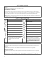
SAFETY SUMMARY (continued)
GENERAL
Any LEDs used in this product are Class 1 LEDs as per IEC 825-l.
ENVIRONMENTAL CONDITIONS
With the exceptions noted, all instruments are intended for indoor use in an installation category II, pollution degree 2
environment. They are designed to operate at a maximum relative humidity of 95% and at altitudes of up to 2000 meters.
Refer to the specifications tables for the ac mains voltage requirements and ambient operating temperature range.
Exceptions: Agilent Technologies Models 6680A, 6681A, 6682A, 6683A, 6684A, 6814A, and 6834A are intended for use
in an installation category III environment.
SAFETY SYMBOL DEFINITIONS
Symbol Description Symbol Description
Direct current Terminal for Line conductor on permanently
installed equipment
Alternating current Caution, risk of electric shock
Both direct and alternating current Caution, hot surface
Three-phase alternating current Caution (refer to accompanying documents)
Earth (ground) terminal In position of a bi-stable push control
Protective earth (ground) terminal Out position of a bi-stable push control
Frame or chassis terminal On (supply)
Terminal for Neutral conductor on permanently
installed equipment
Off (supply)
Terminal is at earth potential(Used for
measurement and control circuits designed to
be operated with one terminal at earth
potential.)
Standby (supply)
Units with this symbol are not completely
disconnected from ac mains when this switch is
off. To completely disconnect the unit from ac
mains, either disconnect the power cord or
have a qualified electrician install an external
switch.
Herstellerbescheinigung
Diese Information steht im Zusammenhang mit den Anforderungen der Maschinenläminformationsverordnung vom 18
Januar 1991.
* Schalldruckpegel Lp <70 dB(A) * Am Arbeitsplatz * Normaler Betrieb * Nach EN 27779 (Typprufung).
Manufacturer’s Declaration
This statement is provided to comply with the requirements of the German Sound Emission Directive, from 18 January
1991.
* Sound Pressure Lp <70 dB(A) *At Operator Position * Normal Operation * According to EN 27779 (Type Test).

5
DECLARATION OF CONFORMITY
according to ISO/IEC Guide 22 and EN 45014
Manufacturer’s Name: Agilent Technologies Inc.
Manufacturer’s Address: 140 Green Pond Road
Rockaway, New Jersey 07866
U.S.A.
declares that the Product
Product Name: a) Single Output System Power Supply
b) General Purpose Power Supply
Model Number: a) Agilent 6641A, 6642A, 6643A, 6644A, 6645A
b) Agilent 6541A, 6542A, 6543A, 6544A, 6545A
conforms to the following Product Specifications:
Safety: IEC 348:1978 / HD 401S1: 1981
1
EMC: CISPR 11:1990 / EN 55011:1991 - Group 1 Class B
IEC 801-2:1991 / EN 50082-1:1992 - 4 kV CD, 8 kV AD
IEC 801-3:1984 / EN 50082-1:1992 - 3 V / m
IEC 801-4:1988 / EN 50082-1:1992 - 0.5 kV Signal Lines
1 kV Power Lines
Supplementary Information:
The product herewith complies with the requirements of the Low Voltage Directive
73/23/EEC and the EMC Directive 89/336/EEC and carries the CE-marking accordingly.
Note 1: The product family was introduced prior to 12/93.
New Jersey January 1997
Location Date Bruce Krueger / Quality Manager
European Contact: Your local Agilent Technologies Sales and Service Office or Agilent Technologies GmbH,
Department TRE, Herrenberger Strasse 130, D-71034 Boeblingen (FAX:+49-7031-14-3143)

6
DECLARATION OF CONFORMITY
according to ISO/IEC Guide 22 and EN 45014
Manufacturer’s Name: Agilent Technologies Inc.
Manufacturer’s Address: 140 Green Pond Road
Rockaway, New Jersey 07866
U.S.A.
declares that the Product
Product Name: a) Single Output System Power Supply
b) General Purpose Power Supply
Model Number: a) Agilent 6651A, 6652A, 6653A, 6654A, 6655A
b) Agilent 6551A, 6552A, 6553A, 6554A, 6555A
conforms to the following Product Specifications:
Safety: IEC 348:1978 / HD 401S1: 1981
1
EMC: CISPR 11:1990 / EN 55011:1991 - Group 1 Class B
IEC 801-2:1991 / EN 50082-1:1992 - 4 kV CD, 8 kV AD
IEC 801-3:1984 / EN 50082-1:1992 - 3 V / m
IEC 801-4:1988 / EN 50082-1:1992 - 0.5 kV Signal Lines
1 kV Power Lines
Supplementary Information:
The product herewith complies with the requirements of the Low Voltage Directive
73/23/EEC and the EMC Directive 89/336/EEC and carries the CE-marking accordingly.
Note 1: The product family was introduced prior to 12/93.
New Jersey January 1997
Location Date Bruce Krueger / Quality Manager
European Contact: Your local Agilent Technologies Sales and Service Offices or Agilent Technologies GmbH,
Department TRE, Herrenberger Strasse 130, D-71034 Boeblingen (FAX:+49-7031-14-3143)

7
DECLARATION OF CONFORMITY
according to ISO/IEC Guide 22 and EN 45014
Manufacturer’s Name: Agilent Technologies Inc.
Manufacturer’s Address: 140 Green Pond Road
Rockaway, New Jersey 07866
U.S.A.
declares that the Product
Product Name: a) Single Output System Power Supply
b) General Purpose Power Supply
Model Number: a) Agilent 6671A, 6672A, 6673A, 6674A, 6675A
b) Agilent 6571A, 6572A, 6573A, 6754A, 6575A
conforms to the following Product Specifications:
Safety: IEC 348:1978 / HD 401S1: 1981
1
EMC: CISPR 11:1990 / EN 55011:1991 - Group 1 Class B
IEC 801-2:1991 / EN 50082-1:1992 - 4 kV CD, 8 kV AD
IEC 801-3:1984 / EN 50082-1:1992 - 3 V / m
IEC 801-4:1988 / EN 50082-1:1992 - 0.5 kV Signal Lines
1 kV Power Lines
Supplementary Information:
The product herewith complies with the requirements of the Low Voltage Directive
73/23/EEC and the EMC Directive 89/336/EEC and carries the CE-marking accordingly.
Note 1: The product family was introduced prior to 12/93.
New Jersey January 1997
Location Date Bruce Krueger / Quality Manager
European Contact: Your local Agilent Technologies Sales and Service Offices or Agilent Technologies GmbH,
Department TRE, Herrenberger Strasse 130, D-71034 Boeblingen (FAX:+49-7031-14-3143)

8
PRINTING HISTORY
The edition and current revision of this manual are indicated below. Reprints of this manual containing minor corrections
and updates may have the same printing date. Revised editions are identified by a new printing date. A revised edition
incorporates all new or corrected material since the previous printing date. Changes to the manual occurring between
revisions are covered by change sheets shipped with the manual. In some cases, the manual change applies only to specific
instruments. Instructions provided on the change sheet will indicate if a particular change applies only to certain
instruments.
Copyright 1993 Agilent Technologies Inc. Edition 1 - November, 1993
Edition 2 - March, 1995
Reprinted - April 2000
This document contains proprietary information protected by copyright. All rights are reserved. No part of this document
may be photocopied, reproduced, or translated into another language without the prior consent of Agilent Technologies.
Information contained in this document is subject to change without notice.
DECLARATION OF CONFORMITY
according to ISO/IEC Guide 22 and EN 45014
Manufacturer’s Name: Agilent Technologies Inc.
Manufacturer’s Address: 140 Green Pond Road
Rockaway, New Jersey 07866
U.S.A.
declares that the Product
Product Name: Single Output System Power Supply
Model Number: Agilent 6680A, 6681A, 6682A, 6683A, 6684A
conforms to the following Product Specifications:
Safety: IEC 348:1978 / HD 401S1: 1981
1
EMC: CISPR 11:1990 / EN 55011:1991 - Group 1 Class A
IEC 801-2:1991 / EN 50082-1:1992 - 4 kV CD, 8 kV AD
IEC 801-3:1984 / EN 50082-1:1992 - 3 V / m
IEC 801-4:1988 / EN 50082-1:1992 - 0.5 kV Signal Lines
1 kV Power Lines
Supplementary Information:
The product herewith complies with the requirements of the Low Voltage Directive
73/23/EEC and the EMC Directive 89/336/EEC and carries the CE-marking accordingly.
Note 1: The product family was introduced prior to 12/93.
New Jersey January 1997
Location Date Bruce Krueger / Quality Manager
European Contact: Your local Agilent Technologies Sales and Service Office or Agilent Technologies GmbH,
Department TRE, Herrenberger Strasse 130, D-71034 Boeblingen (FAX:+49-7031-14-3143)

9
Table Of Contents
1 General Information
Introduction...................................................................................................................................................15
Safety Considerations................................................................................................................................16
Instrument Identification ...........................................................................................................................16
Options......................................................................................................................................................16
Accessories................................................................................................................................................17
Description................................................................................................................................................17
Front Panel Programming........................................................................................................................18
Remote Programming..............................................................................................................................18
Analog Programming ..............................................................................................................................18
Output Characteristic...............................................................................................................................19
Specifications and Supplemental Characteristics ......................................................................................19
Performance Specifications for Series 664xA.........................................................................................20
Performance Specifications for Series 665xA.........................................................................................25
Performance Specifications for Series 667xA.........................................................................................30
Performance Specifications for Series 668xA.........................................................................................35
Supplemental Characteristics for Series 664xA ......................................................................................21
Supplemental Characteristics for Series 665xA ......................................................................................26
Supplemental Characteristics for Series 667xA ......................................................................................31
Supplemental Characteristics for Series 668xA ......................................................................................36
Supplemental GPIB Characteristics for All Models................................................................................40
Operator Replaceable Parts List ................................................................................................................41
2 Installation
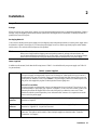
Inspection......................................................................................................................................................43
Damage....................................................................................................................................................43
Packaging Material..................................................................................................................................43
Items Supplied.........................................................................................................................................43
Location and Temperature.........................................................................................................................44
Bench Operation......................................................................................................................................44
Rack Mounting........................................................................................................................................44
Temperature Performance .......................................................................................................................44
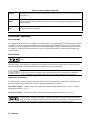
Input Power Source ...................................................................................................................................45
Series 664xA and 665xA Supplies..........................................................................................................45
Series 667xA Supplies.............................................................................................................................45
Series 668xA Supplies.............................................................................................................................47
3 Turn-on Checkout
Introduction...................................................................................................................................................49
Preliminary Checkout..................................................................................................................................49
Power-on Checkout.....................................................................................................................................50
Using the Keypad..........................................................................................................................................50
Shifted Keys..............................................................................................................................................50
Backspace Key..........................................................................................................................................50
Output Checkout..........................................................................................................................................50
Checking the Voltage Function.................................................................................................................51
Checking the Current Function..................................................................................................................52
Checking the Save and Recall Functions.....................................................................................................53
Determining GPIB Address.........................................................................................................................53
In Case of Trouble.......................................................................................................................................53
Line Fuse...................................................................................................................................................53
Condensation Fault (Series 668xA only)...................................................................................................55
Error Messages..........................................................................................................................................55

10
4 User Connections
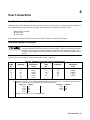
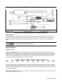
Rear Panel Connections.................................................................................................................................57
Load Wire Selection....................................................................................................................................57
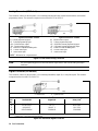
Analog Connector........................................................................................................................................58
Digital Connector........................................................................................................................................58
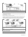
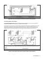
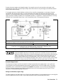
Connecting Series 664xA and 665xA Power Supplies to the Load.............................................................59
Output Isolation.........................................................................................................................................59
Load Considerations..................................................................................................................................59
Local Voltage Sensing ..............................................................................................................................60
Remote Voltage Sensing ...........................................................................................................................61
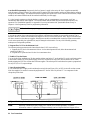
Operating Configurations..........................................................................................................................63
Connecting One Supply to the Load.........................................................................................................63
Connecting Supplies in Auto-Parallel.......................................................................................................64
Connecting Supplies in Series..................................................................................................................65
External Voltage Control...........................................................................................................................65
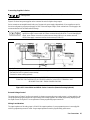
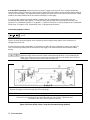
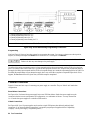
Connecting Series 667xA Power Supplies to the Load ...............................................................................66
Output Isolation.........................................................................................................................................66
Load Considerations..................................................................................................................................67
Local Voltage Sensing...............................................................................................................................68
Remote Voltage Sensing ...........................................................................................................................68
Operating Configurations..........................................................................................................................70
Connecting One Supply to a Single Load......................................................................................................70
Connecting One Supply to Multiple Loads ..............................................................................................70
Connecting Supplies in Auto-Parallel.......................................................................................................71
Connecting Supplies in Series..................................................................................................................72
External Voltage Control...........................................................................................................................73
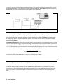
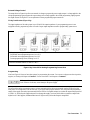
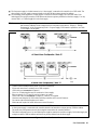
Connecting Series 668xA Power Supplies to the Load ...............................................................................74
Output Isolation.........................................................................................................................................74
Load Considerations..................................................................................................................................74
Local Voltage Sensing...............................................................................................................................75
Remote Voltage Sensing ...........................................................................................................................75
Operating Configurations..........................................................................................................................76
Connecting One Supply to a Single Load.................................................................................................77
Connecting One Supply to Multiple Loads ..............................................................................................77
Connecting Supplies in Auto-Parallel............................................................................................................78
Connecting Supplies in Series.................................................................................................................78
External Voltage Control...........................................................................................................................79
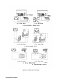
Controller Connections..............................................................................................................................80
Stand-Alone Connections........................................................................................................................80
Linked Connections.................................................................................................................................80
5 Front Panel Operation
Introduction...................................................................................................................................................83
Getting Acquainted.....................................................................................................................................83
Programming the Output............................................................................................................................86
Introduction...............................................................................................................................................86
Establishing Initial Conditions. .................................................................................................................86
Programming Voltage ...............................................................................................................................87
Programming Overvoltage Protection.......................................................................................................87
Programming Current................................................................................................................................88
Programming Overcurrent Protection........................................................................................................89
CV Mode vs. CC Mode..............................................................................................................................89
Unregulated Operation ...............................................................................................................................90
Saving and Recalling States ......................................................................................................................90
Turn-on Conditions ...................................................................................................................................90
Setting the GPIB Address..............................................................................................................................91

11
A Calibration
Introduction...................................................................................................................................................93
Equipment Required...................................................................................................................................93
General Procedure......................................................................................................................................93
Parameters Calibrated................................................................................................................................93
Test Setup..................................................................................................................................................94
Front Panel Calibration .................................................................................................................................94
Entering the Calibration Values ............................................................................................................... 94
Saving the Calibration Constants...............................................................................................................94
Disabling the Calibration Mode ................................................................................................................94
Changing the Calibration Password............................................................................................................94
Recovering From Calibration Problems.....................................................................................................97
Calibration over the GPIB.............................................................................................................................98
Calibration Example..................................................................................................................................98
Calibration Language Dictionary ..............................................................................................................98
CAL:CURR.............................................................................................................................................98
CAL:CURR:LEV....................................................................................................................................98
CAL:CURR:MON (Series 668xA only)..................................................................................................99
CAL:PASS..............................................................................................................................................99
CAL:SAVE .............................................................................................................................................99
CAL:STAT..............................................................................................................................................99
CAL:VOLT...........................................................................................................................................100
CAL:VOLT:LEV ..................................................................................................................................100
CAL:VOLT:PROT................................................................................................................................100
Agilent-Basic Calibration Program .........................................................................................................100
B Operation Verification
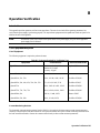
Introduction.................................................................................................................................................103
Test Equipment Required.........................................................................................................................103
List of Equipment....................................................................................................................................103
Current Monitoring Resistor....................................................................................................................103
Performing the Tests ................................................................................................................................105
General Measurement Techniques ..........................................................................................................105
Programming the Power Supply..................................................................................................................105
Order of Tests..........................................................................................................................................105
Turn-on Checkout....................................................................................................................................105
Voltage Programming and Readback Accuracy..........................................................................................105
Current Programming and Readback Accuracy.......................................................................................106
Verification Test Parameters....................................................................................................................107
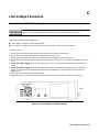
C Line Voltage Conversion
Series 664xA and 665xA Supplies..............................................................................................................115
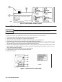
Series 667xA Supplies..............................................................................................................................116
Series 668xA Supplies..............................................................................................................................117
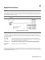
D Digital Port Functions
Digital Connector........................................................................................................................................119
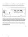
Fault/Inhibit Operation.............................................................................................................................119
Changing the Port Configuration.................................................................................................................122
Digital I/O Operation...................................................................................................................................122
Relay Link Operation..................................................................................................................................123
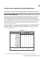
E Current Loop Compensation
Function of Loop Compensation.................................................................................................................125
Setting the Loop Compensation Switch.......................................................................................................128

12
F Using Agilent 668xA Series Power Supplies in Autoparallel
Auto parallel Procedure...............................................................................................................................129
Index
References...................................................................................................................................................131
Agilent Sales and Support Offices
Contacts.......................................................................................................................................................135

13
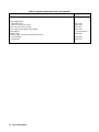
List of Figures
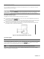
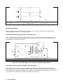
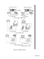
2-1. Series 664xA/665xA Power Connection..................................................................................45
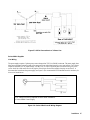
2-2. Connecting the Series 667xA Power Cord...............................................................................46
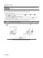
2-3. 667xA Connection to a 3-Phase Line.......................................................................................47
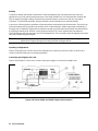
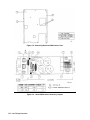
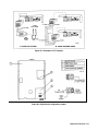
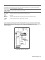
2-4. Series 668xA Overall Wiring Diagram....................................................................................47
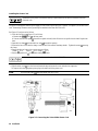
2-5. Connecting the Series 668xA Power Cord...............................................................................48
3-1. Series 667xA Line Fuse...........................................................................................................54
4-1. Rear Panel Analog Connector..................................................................................................58
4-2. Rear Panel Digital Connector ..................................................................................................58
4-3a. Series 664xA/665xA Rear Panel Output Connections.............................................................59
4-3b. Series 664xA/665xA Single Load Connection.........................................................................62
4-3c. Series 664xA/665xA Multiple Load Connection.....................................................................63
4-3d. Series 664xA/665xA Auto-Parallel Connection ......................................................................63
4-3e. Using Series Diodes with Series 664xA/665xA Auto-Parallel Operation................................64
4-3f. Series 664xA/665xA Series Connection..................................................................................65
4-3g. Series 664xA/665xA Analog Programming Connections ......................................................66
4-4a. Series 667xA Rear Panel Output Connections.........................................................................67
4-4b. Series 667xA Sense Lead Bypass Network..............................................................................70
4-4c. Series 667xA Single Load Connection ....................................................................................70
4-4d. Series 667xA Multiple Load Connection.................................................................................71
4-4e. Series 667xA Auto-Parallel Connection ..................................................................................71
4-4f. Series 667xA Series Connection..............................................................................................72
4-4g. Series 667xA Analog Programming Connections....................................................................73
4-5a. Series 668xA Rear Panel Output Connections.........................................................................74
4-5b. Series 668xA Sense Lead Bypass Network.............................................................................76
4-5c. Series 668xA Single Load Connection . ..................................................................................77
4-5d. Series 668xA Multiple Load Connection.................................................................................77
4-5e. Series 668xA Auto-Parallel Connection. .................................................................................78
4-5f. Series 668xA Series Connection..............................................................................................79
4-5g. Series 668xA Analog Programming Connections....................................................................80
4-6. Controller Connections............................................................................................................81
5-1. Front Panel Controls and Indicators.........................................................................................84
5-2. Typical Power Supply Operating Curve ..................................................................................87
A-l. Calibration Test Setup..............................................................................................................95
A-2. Agilent BASIC Calibration Program .....................................................................................101
B-l. Verification Test Setup ..........................................................................................................104
C-l. Series 664xA Line Select Switches........................................................................................115
C-2. Series 665xA Line Select Jumpers.........................................................................................116
C-3. Series 667xA Line Select Switch ..........................................................................................116
C-4. Removing the Series 668xA Inner Cover...............................................................................118
C-5. Series 668xA Line Conversion Jumpers................................................................................118
D-1. Digital Port Connector...........................................................................................................119
D-2. Example of Inhibit Input........................................................................................................120
D-3. Examples of Fault Outputs.....................................................................................................121
D-4. Digital Port Configuration Jumper.........................................................................................121
D-5. Digital I/O Port Applications ................................................................................................122
D-6. Relay Link Connections.........................................................................................................123
E-l. CC Loop Compensation Curves for Series 668xA.................................................................126
E-2. CC Loop Compensation Switch for Series 668xA.................................................................128
F-1. Master/Slave Current Division...............................................................................................130

14
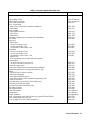
List of Tables
l-la. Performance Specifications - Series 664xA.............................................................................20
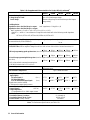
l-lb. Supplemental Characteristics - Series 664xA ..........................................................................21
1-2a. Performance Specifications - Series 665xA............................................................................25
1-2b. Supplemental Characteristics - Series 665xA ..........................................................................26
1-3a. Performance Specifications - Series 667xA............................................................................30
1-3b. Supplemental Characteristics - Series 667xA .........................................................................31
1-4a. Performance Specifications - Series 668xA.............................................................................35
1-4b. Supplemental Characteristics- Series 668xA ...........................................................................36
1-5. Supplemental GPIB Characteristics for All Models ................................................................40
1-6. Operator Replaceable Parts List...............................................................................................41
2-1. Items Supplied .........................................................................................................................43
3-1. Checking the Voltage Functions..............................................................................................50
3-2. Checking the Current Functions...............................................................................................52
3-3. Power-on Selftest Errors..........................................................................................................55
3-4. Runtime Error Messages..........................................................................................................56
4-1. Copper Wire Ampere Capacity and Resistance .......................................................................57
5-1. Front Panel Controls and Indicators.........................................................................................84
A-l. Equipment Required for Calibration........................................................................................93
A-2. Typical Front Panel Calibration Procedure..............................................................................96
A-3. GPIB Calibration Error Messages...........................................................................................97
B-l. Equipment Required for Verification Tests ...........................................................................103
B-2. Voltage Programming and Readback Accuracy Tests...........................................................105
B-3. Current Programming and Readback Accuracy Test.............................................................106
B-4. Test Parameters for Series 664xA..........................................................................................107
B-5. Test Parameters for Series 665xA..........................................................................................109
B-6. Test Parameters for Series 667xA..........................................................................................111
B-7. Test Parameters for Series 668xA..........................................................................................113
E-l. Settings for CC Loop Compensation Switch..........................................................................125

General Information 15
1
General Information
Introduction
Two guides are shipped with your power supply - an Operating Guide (this document) and a Programming Guide. You will
find information on the following tasks in these guides:
Quick Document Orientation
1
Topic Location
Calibrating the power supply Appendix A - this guide
Compatibility programming language Appendix B - Programming Guide
Configuring the digital port Appendix D - this guide
Line voltage:
Connecting ac power source Chapter 2 - this guide
Converting the ac source voltage Appendix B - this guide
Source current, frequency, and power ratings Chapter 1- this guide
Operator replaceable parts Chapter 1- this guide
Operator troubleshooting Chapter 3 - this guide
Output impedance characteristics Chapter 1- this guide
Power supply accessories Chapter 1- this guide
Power supply operating characteristics Chapter 1- this guide
Power supply options Chapter 1- this guide
Power supply performance specifications Chapter 1- this guide
Programming
discrete fault inhibit (DFI) operation Chapter 4 - Programming Guide
from the analog port Chapter 4 - this guide
from the front panel Chapter 5 - this guide
over the GPIB Chapter 2 - Programming Guide
remote inhibit (RI) operation Chapter 4 - Programming Guide
status registers Chapter 4 - Programming Guide
Quick operating checkout (without load) Chapter 3 - this guide
Rack mounting Chapter 2 - this guide
SCPI programming language Chapter 3 - Programming Guide
Wiring
analog programming port Chapter 4 - this guide
discrete fault indicator (DFI) operation Appendix D - this guide
digital port Appendix D - this guide
GPIB controller Chapter 4 - this guide
load or loads Chapter 4 - this guide
local sensing Chapter 4 - this guide
remote inhibit (RI) operation Chapter 4 - this guide
remote sensing Chapter 4 - this guide
1
See the Table of Contents for complete list of topics.

General Information16
Safety Considerations
This power supply is a Safety Class 1 instrument, which means it has a protective earth terminal. That terminal must be
connected to earth ground through a power source equipped with a 3-wire ground receptacle. Refer to the Safety Summary
page at the beginning of this guide for general safety information. Before installation or operation, check the power supply
and review this guide for safety warnings and instructions. Safety warnings for specific procedures are located at
appropriate places in the guide.
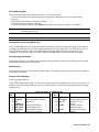
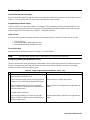
Instrument Identification
The power supply is identified by a unique two-part serial number, such as, 3343A-00177. The first part, or prefix, is a
number-letter combination that provides the following information:
3343 = The year and week of manufacture or last significant design change. Add 1960 to the first two digits to determine
the year. For example, 32=1992, 33=1993, etc. The last two digits specify the week of the year (43 = the 43rd
week).
A = The letter indicates the country of manufacture, where A = USA.
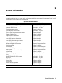
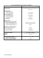
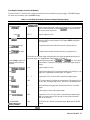
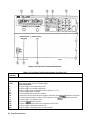
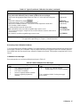
Options
List of Options
Option Description Used with Agilent Series
664xA 665xA 667xA 668xA
100
Input power 100 Vac, nominal x x
200
Input power 200 Vac, nominal x
220
Input power 220 Vac, nominal x x
240
Input power 240 Vac, nominal x x
400
Input power 360-440 Vac, 3 -phase x
601
Output connector kit required for bench applications x
602
Bus bar spacers for paralleling power supplies x
831
Power cord, 12 AWG, UL listed, CSA certified, without plug x
832
Power cord, 4 mm
2
, harmonized, without plug x
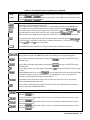
834
Power cord, 10 AWG, UL listed, CSA certified, without plug x
841
Power cord, 12 AWG, UL listed, CSA certified, with NEMA
6-20P 20A/250V plug
x
842
Power cord, 4 mm
2
, harmonized, with IEC 309 32A/220V
plug
x
843
Power cord, 12 AWG, UL listed, CSA certified, with JIS
C8303 25A/250V plug
x
844
Power cord, 10 AWG, UL listed, CSA certified, with NEMA
L6-30P-30A/250V locking plug
x
861
Power cord, 10 AWG, UL listed, 300 V, CSA certified,
without plug
x
862
Power cord, 2.5 mm
2
, 4-wire, harmonized, without plug
x
908
Rack mount kit (Agilent 5062-3974) x
Rack mount kit (Agilent 5062-3977) Support rails (E3663A)
are required.
xx
Rack mount kit (Agilent 5062-3977 & 5062-3974) Support
rails (E3663A) are required.
x

General Information 17
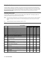
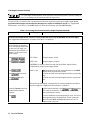
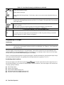
List of Options (continued)
Option Description Used with Agilent Series
664xA 665xA 667xA 668xA
909
Rack mount kit with handles (Agilent 5062-3975) x
909 Rack mount kit with handles (Agilent 5062-3983) Support
rails (E3663A) are required.
xx
Rack mount kit with handles (Agilent 5062-3983 &
5062-3974) Support rails (E3663A) are required.
x
910
Service manual with extra Operating and Programming
Guides
xx xx
ABD
Quick-Start Guide German x x x x
ABE
Quick-Start Guide, Spanish x x x x
ABF
Quick-Start Guide, French x x x x
ABJ
Operating Manual, Japanese x x x x
ABZ
Quick-Start Guide, Italian x x x x
AB0
Quick-Start Guide, Taiwanese x x x x
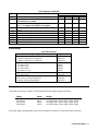
Accessories
List of Accessories
Description Agilent No. Agilent No.
Fuse replacement kit for Series 668xA
16 AM for 360-440 Vac, 3-phase line 5060-3512
30 AM for 180-235 Vac, 3-phase line 5060-3513
GPIB cable (all models)
0.5 meters (1.6 ft) 10833D
1.0 meter (3.3 ft) 10833A
2.0 meters (6.6 ft) 10833B
4.0 meters ( 13 .2 ft) 10833C
Serial link cable (all models)
2.0 meters (6.6 ft) 5080-2148
Slide mount kit
heavy duty, for Series 667xA/668xA 1494-0058
standard, for Series 664xA/665xA 1494-0059
Description
These units form a family of unipolar, GPIB programmable power supplies organized as follows:
Family Power Models
Series 664xA 200 W AGILENT 6641A, 6642A, 6643A, 6644A, 6645A
Series 665xA 500 W AGILENT 6651A, 6652A, 6653A, 6654A, 6655A
Series 667xA 2000 W AGILENT 6671A, 6672A, 6673A, 6674A, 6675A
Series 668xA 5000 W AGILENT 6680A, 6681A, 6682A, 6683A, 6684A
Each power supply is programmable locally from the front panel or remotely via a rear-panel analog control port.

General Information18
Operational features include:
■ Constant voltage (CV) or constant current (CC) output over the rated output range.
■ Built-in overvoltage (OV), overcurrent (OC), and overtemperature (OT) protection.
■ Automatic turn-on selftest.
■ Pushbutton nonvolatile storage and recall of up to 5 operating states (4 in Series 668xA supplies).
■ Local or remote sensing of output voltage.
■ Auto-parallel operation for increased total current.
■ Series operation for increased total voltage.
■ Analog input for remote programming of voltage and current.
■ Voltage output for external monitoring of output current.
■ User calibration from the front panel.
Front Panel Programming
The front panel has both rotary (RPG) and keypad controls for setting the output voltage and current. The panel display
provides digital readouts of the output voltage and current. Other front panel controls permit:
■ Enabling or disabling the output.
■ Setting the overvoltage protection (OVP) trip voltage.
■ Enabling or disabling the overcurrent protection (OCP) feature.
■ Saving and recalling operating states.
■ Setting the GPIB address.
■ Reading GPIB error message codes.
■ Calibrating the power supply, including changing the calibration protection password.
Remote Programming
The power supply may be remotely programmed via the GPIB bus and/or from an analog input port. GPIB programming is
with SCPI (Standard Commands for Programmable Instruments) commands that make the power supply programs
compatible with those of other GPIB instruments. (A software-controlled Compatibility Mode also permits programming in
the command set of the Agilent 6030xA Autoranging Series.) In addition to control functions, SCPI programming permits
writing to the front panel LCD and complete calibration functions. Power supply status registers permit remote monitoring
of the following conditions:
■ Overvoltage, overcurrent, overtemperature, and unregulated states.
■ Operating mode (constant voltage or constant current).
■ State of the RI (remote inhibit) input signal.
■ Power-on status (PON).
■ Status of the output queue (QYE).
■ Pending triggers (WTG).
■ GPIB interface programming errors (CME, DDE, and EXE).
■ Calibration state (enabled or disabled).
The status registers can be programmed to generate an output fault signal (FLT) upon the occurrence of one or more
selected status events.
Analog Programming
The power supply has an analog port for remote programming. The output voltage and/or current of the power supply may
be controlled by individual d-c programming voltages applied to this port. The port also provides a monitor output that
supplies a d-c voltage proportional to the output current.

General Information 19
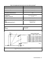
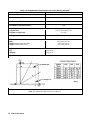
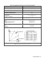
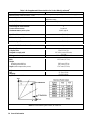
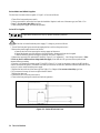
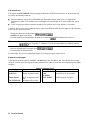
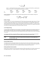
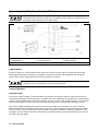
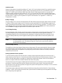
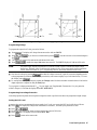
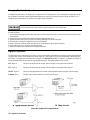
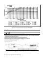
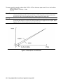
Output Characteristic
General
The power supply can operate in either CV (constant voltage) or CC (constant current) over its voltage and current ratings
(see Table 1-l). The operating locus is shown by the Output Characteristic Curve in Table 1-2. The operating point is
determined by the voltage setting (V
s
), the current setting (I
s
), and the load impedance. Two operating points are shown.
Point 1 is defined by the load line cutting the operating locus in the constant-voltage region. This region defines the CV
mode. Point 2 is defined by the load line cutting the operating locus in the constant-current region. This region defines the
CC mode.
Downprogramming
The power supply can sink current for more rapid down programming in the CV mode. For Series 664xA and 665xA
supplies, this capability is defined by the second quadrant area (-I
s
) of the Output Characteristic Curve. These supplies can
sink about 20% of their maximum rated positive output current. For Series 667xA and 668xA power supplies, this is an
uncharacterized current-sinking area that provides a limited downprogramming capability.
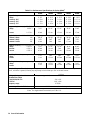
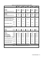
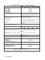
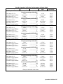
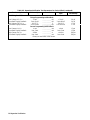
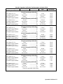
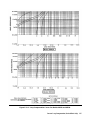
Specifications and Supplemental Characteristics
Tables 1-1 through 1-4 list the specifications and supplemental characteristics for the Series 664xA, 665xA, 667xA, and
668xA power supplies. The organization is as follows:
Series Specifications Characteristics
6641A-6645A Table l-la Table l-lb
6651A-6655A Table 1-2a Table 1-2b
6671A-6675A Table 1-3a Table 1-3b
6680A-6684A Table 1-4a Table 1-4b
Specifications are performance parameters warranted over the specified temperature range.
Supplemental Characteristics are not warranted but are descriptions of performance determined either by design or type
testing.

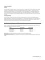
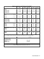
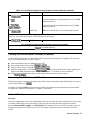
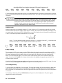
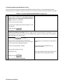
General Information20
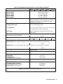
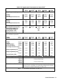
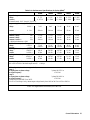
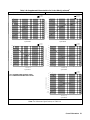
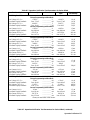
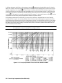
Table 1-1a. Performance Specifications for Series 664xA
1
Parameter Agilent Model Number
6641A 6642A 6643A 6644A 6645A
Output Ratings
Voltage: 0 - 8 V 0 - 20 V 0 - 35 V 0 - 60 V 0 - 120 V
Current:@ 40°C
0 - 20 A 0 - 10 A 0 - 6 A 0 - 3.5 A 0 - 1.5 A
Current:@ 50°C
0 - 18 A 0 - 9 A 0 - 5.4 A 0 - 3.2 A 0 - 1.4 A
Current:@ 55°C
0 - 17 A 0 - 8.5 A 0 - 5.1 A 0 - 3.0 A 0 -1.4 A
Programming Accuracy (@ 25 ± 5 °C)
Voltage: 0.06% +
5 mV
10 mV
15 mV
26 mV 51 mV
Current: 0 . l5 % + 26 mA
13 mA
6.7 mA
4.1 mA
1.7 mA
Ripple & Noise (from 20 Hz to 20 MHz with outputs ungrounded, or with either output terminal grounded)
Constant Voltage: rms
300 µV 300 µV 400 µV 500 µV 700 µV
Constant Voltage: p-p 3 mV 3 mV 4 mV 5 mV 7 mV
Constant Current: rms
10 mA
5 mA 3 mA 1.5 mA 1 mA
Readback Accuracy (from front panel or over GPIB with respect to actual output @ 25 ±:5 °C)
Voltage: 0.07% + 6 mV 15 mV 25 mV 40 mV 80 mV
+Current 0.15% + 18 mA 9.1 mA 5 mA 3 mA 1.3 mA
-Current 0.35% +
40 mA 20 mA 12 mA 6.8 mA 2.9 mA
Load Regulation (change in output voltage or current for any load change within ratings)
Voltage
1 mV 2 mV 3 mV 4 mV 5 mV
Current:
1 mA 0.5 mA 0.25 mA 0.25 mA 0.25 mA
Line Regulation (change in output voltage or current for any line change within ratings
Voltage:
0.5 mV 0.5 mV 1 mV 1 mV 2 mV
Current:
1 mA 0.5 mA 0.25 mA 0.25 mA 0.25 mA
Transient Response Time (for the output voltage to recover to its previous level (within 0.1% of the rated voltage or
20 mV, whichever is greater) following any step change in load current up to 50% of the rated current.
< 100 µs
AC Input Ratings (selectable via internal switching - see Appendix B)
Nominal line voltage
100,120,220,240 Vac:
230 Vac:
F requency range:
-13%, +6 %
-10%, +10%
47-63 Hz
Output Terminal Isolation
±240 Vdc (maximum, from chassis ground)
Notes:
1
For Supplemental Characteristics, see Table 1-1b.
Page is loading ...
Page is loading ...
Page is loading ...
Page is loading ...
Page is loading ...
Page is loading ...
Page is loading ...
Page is loading ...
Page is loading ...
Page is loading ...
Page is loading ...
Page is loading ...
Page is loading ...
Page is loading ...
Page is loading ...
Page is loading ...
Page is loading ...
Page is loading ...
Page is loading ...
Page is loading ...
Page is loading ...
Page is loading ...
Page is loading ...
Page is loading ...
Page is loading ...
Page is loading ...
Page is loading ...
Page is loading ...
Page is loading ...
Page is loading ...
Page is loading ...
Page is loading ...
Page is loading ...
Page is loading ...
Page is loading ...
Page is loading ...
Page is loading ...
Page is loading ...
Page is loading ...
Page is loading ...
Page is loading ...
Page is loading ...
Page is loading ...
Page is loading ...
Page is loading ...
Page is loading ...
Page is loading ...
Page is loading ...
Page is loading ...
Page is loading ...
Page is loading ...
Page is loading ...
Page is loading ...
Page is loading ...
Page is loading ...
Page is loading ...
Page is loading ...
Page is loading ...
Page is loading ...
Page is loading ...
Page is loading ...
Page is loading ...
Page is loading ...
Page is loading ...
Page is loading ...
Page is loading ...
Page is loading ...
Page is loading ...
Page is loading ...
Page is loading ...
Page is loading ...
Page is loading ...
Page is loading ...
Page is loading ...
Page is loading ...
Page is loading ...
Page is loading ...
Page is loading ...
Page is loading ...
Page is loading ...
Page is loading ...
Page is loading ...
Page is loading ...
Page is loading ...
Page is loading ...
Page is loading ...
Page is loading ...
Page is loading ...
Page is loading ...
Page is loading ...
Page is loading ...
Page is loading ...
Page is loading ...
Page is loading ...
Page is loading ...
Page is loading ...
Page is loading ...
Page is loading ...
Page is loading ...
Page is loading ...
Page is loading ...
Page is loading ...
Page is loading ...
Page is loading ...
Page is loading ...
Page is loading ...
Page is loading ...
Page is loading ...
Page is loading ...
Page is loading ...
Page is loading ...
Page is loading ...
Page is loading ...
-
 1
1
-
 2
2
-
 3
3
-
 4
4
-
 5
5
-
 6
6
-
 7
7
-
 8
8
-
 9
9
-
 10
10
-
 11
11
-
 12
12
-
 13
13
-
 14
14
-
 15
15
-
 16
16
-
 17
17
-
 18
18
-
 19
19
-
 20
20
-
 21
21
-
 22
22
-
 23
23
-
 24
24
-
 25
25
-
 26
26
-
 27
27
-
 28
28
-
 29
29
-
 30
30
-
 31
31
-
 32
32
-
 33
33
-
 34
34
-
 35
35
-
 36
36
-
 37
37
-
 38
38
-
 39
39
-
 40
40
-
 41
41
-
 42
42
-
 43
43
-
 44
44
-
 45
45
-
 46
46
-
 47
47
-
 48
48
-
 49
49
-
 50
50
-
 51
51
-
 52
52
-
 53
53
-
 54
54
-
 55
55
-
 56
56
-
 57
57
-
 58
58
-
 59
59
-
 60
60
-
 61
61
-
 62
62
-
 63
63
-
 64
64
-
 65
65
-
 66
66
-
 67
67
-
 68
68
-
 69
69
-
 70
70
-
 71
71
-
 72
72
-
 73
73
-
 74
74
-
 75
75
-
 76
76
-
 77
77
-
 78
78
-
 79
79
-
 80
80
-
 81
81
-
 82
82
-
 83
83
-
 84
84
-
 85
85
-
 86
86
-
 87
87
-
 88
88
-
 89
89
-
 90
90
-
 91
91
-
 92
92
-
 93
93
-
 94
94
-
 95
95
-
 96
96
-
 97
97
-
 98
98
-
 99
99
-
 100
100
-
 101
101
-
 102
102
-
 103
103
-
 104
104
-
 105
105
-
 106
106
-
 107
107
-
 108
108
-
 109
109
-
 110
110
-
 111
111
-
 112
112
-
 113
113
-
 114
114
-
 115
115
-
 116
116
-
 117
117
-
 118
118
-
 119
119
-
 120
120
-
 121
121
-
 122
122
-
 123
123
-
 124
124
-
 125
125
-
 126
126
-
 127
127
-
 128
128
-
 129
129
-
 130
130
-
 131
131
-
 132
132
-
 133
133


Ask a question and I''ll find the answer in the document
Finding information in a document is now easier with AI
Related papers
-
Agilent Technologies E4356A User manual
-
-
-
-
-
-
-
Agilent Technologies Network Card E3632A User manual
-
-
Other documents
-
HP 6269A User manual
-
B&K Precision PVS10005 User manual
-
-
 B & K Precision Model XLN10014-GL User manual
-
 XP PLS6002005 User manual
-
SEFRAM 8624 User manual
-
Tektronix PS2521G User manual
-
Megger LCR131 User manual
-
Elenco XP-770 Owner's manual
-

