Page is loading ...

OPERATOR’S
MANUAL
Model C300NP
Non-Pressurized Slush Freezer
9/22//06 (Original Publication)
(Updated 6/28/2018)
Original Operating Instructions
055072NP

Complete this page for quick reference when service is required:
Taylor Distributor: __________________________________________________________
Address:_________________________________________________________________
Phone: _______________________________________________________
___________
Service: _________________________________________________________________
Parts: ___________________________________________________________________
Date of Installation: ________________________________________________________
Information found on the data label:
Model Number: ___________________________________________________________
Serial Number: ____________________________________________________________
Electrical Specs: Voltage__________________ Cycle__________
Phase__________________________________
Maximum Fuse Size: ______________________________________________________ A
Minimum Wire Ampacity: ___________________________________________________ A
Note: Continuing research results in steady improvements; therefore, information in this manual is subject to change
without notice.
Note: Only instructions originating from the factory or its authorized translation representative(s) are considered to be
the original set of instructions.
© 2006 Taylor Company
055072NP
Any unauthorized reproduction, disclosure, or distribution of copies by any person of any portion of this work may be
a violation of copyright law of the United States of America and other countries, could result in the awarding of
statutory damages of up to $250,000 (17 USC 504) for infringement, and may result in further civil and criminal
penalties. All rights reserved.
Taylor Company
750 N. Blackhawk Blvd.
Rockton, IL 61072

Table of Contents
055072NP i
Section 1: To the Installer
Installer Safety . . . . . . . . . . . . . . . . . . . . . . . . . . . . . . . . . . . . . . . . . . . . . . . . . . . . . . . 1-1
Site Preparation . . . . . . . . . . . . . . . . . . . . . . . . . . . . . . . . . . . . . . . . . . . . . . . . . . . . . . 1-1
Air-Cooled Units . . . . . . . . . . . . . . . . . . . . . . . . . . . . . . . . . . . . . . . . . . . . . . . . . . . . . . 1-2
Water-Cooled Refrigeration Units . . . . . . . . . . . . . . . . . . . . . . . . . . . . . . . . . . . . . . . . . 1-2
Water Connections . . . . . . . . . . . . . . . . . . . . . . . . . . . . . . . . . . . . . . . . . . . . . . . . . . . . 1-2
Electrical Connections. . . . . . . . . . . . . . . . . . . . . . . . . . . . . . . . . . . . . . . . . . . . . . . . . . 1-2
Beater Rotation . . . . . . . . . . . . . . . . . . . . . . . . . . . . . . . . . . . . . . . . . . . . . . . . . . . . . . . 1-3
Section 2: To the Operator
Compressor Warranty Disclaimer . . . . . . . . . . . . . . . . . . . . . . . . . . . . . . . . . . . . . . . . . 2-2
Section 3: Safety
Section 4: Operator Parts Identification
Exploded View . . . . . . . . . . . . . . . . . . . . . . . . . . . . . . . . . . . . . . . . . . . . . . . . . . . . . . . 4-1
Beater Door Assembly . . . . . . . . . . . . . . . . . . . . . . . . . . . . . . . . . . . . . . . . . . . . . . . . . 4-2
Accessories. . . . . . . . . . . . . . . . . . . . . . . . . . . . . . . . . . . . . . . . . . . . . . . . . . . . . . . . . . 4-3
Section 5: User Interface
Symbol Definitions . . . . . . . . . . . . . . . . . . . . . . . . . . . . . . . . . . . . . . . . . . . . . . . . . . . . 5-1
Control Switch. . . . . . . . . . . . . . . . . . . . . . . . . . . . . . . . . . . . . . . . . . . . . . . . . . . . . . . . 5-2
Liquid Crystal Display . . . . . . . . . . . . . . . . . . . . . . . . . . . . . . . . . . . . . . . . . . . . . . . . . . 5-2
Operational Mode Display. . . . . . . . . . . . . . . . . . . . . . . . . . . . . . . . . . . . . . . . . . . . . . . 5-2
Operator Menu Display . . . . . . . . . . . . . . . . . . . . . . . . . . . . . . . . . . . . . . . . . . . . . . . . . 5-2
Operator Menu Timeout . . . . . . . . . . . . . . . . . . . . . . . . . . . . . . . . . . . . . . . . . . . . . . . . 5-2
Finding Current Fault Conditions . . . . . . . . . . . . . . . . . . . . . . . . . . . . . . . . . . . . . . . . . 5-2
Syrup Out Indicator . . . . . . . . . . . . . . . . . . . . . . . . . . . . . . . . . . . . . . . . . . . . . . . . . . . . 5-7
CO2 Out Indicator . . . . . . . . . . . . . . . . . . . . . . . . . . . . . . . . . . . . . . . . . . . . . . . . . . . . . 5-7
Water Out Indicator. . . . . . . . . . . . . . . . . . . . . . . . . . . . . . . . . . . . . . . . . . . . . . . . . . . . 5-7
Audio Alarm Silencer. . . . . . . . . . . . . . . . . . . . . . . . . . . . . . . . . . . . . . . . . . . . . . . . . . . 5-7
Product Light. . . . . . . . . . . . . . . . . . . . . . . . . . . . . . . . . . . . . . . . . . . . . . . . . . . . . . . . . 5-7
Sampling Valve . . . . . . . . . . . . . . . . . . . . . . . . . . . . . . . . . . . . . . . . . . . . . . . . . . . . . . . 5-7
Daily Procedures. . . . . . . . . . . . . . . . . . . . . . . . . . . . . . . . . . . . . . . . . . . . . . . . . . . . . . 5-7

ii 055072NP
Table of Contents
Section 6: Operating Procedures
Assembly . . . . . . . . . . . . . . . . . . . . . . . . . . . . . . . . . . . . . . . . . . . . . . . . . . . . . . . . . . . 6-1
Sanitizing . . . . . . . . . . . . . . . . . . . . . . . . . . . . . . . . . . . . . . . . . . . . . . . . . . . . . . . . . . . 6-6
Priming/Brixing . . . . . . . . . . . . . . . . . . . . . . . . . . . . . . . . . . . . . . . . . . . . . . . . . . . . . . . 6-8
120 Day Closing Procedure . . . . . . . . . . . . . . . . . . . . . . . . . . . . . . . . . . . . . . . . . . . . 6-10
Draining Product from the Freezing Cylinder . . . . . . . . . . . . . . . . . . . . . . . . . . . . . . . 6-10
Rinsing . . . . . . . . . . . . . . . . . . . . . . . . . . . . . . . . . . . . . . . . . . . . . . . . . . . . . . . . . . . .6-10
Cleaning . . . . . . . . . . . . . . . . . . . . . . . . . . . . . . . . . . . . . . . . . . . . . . . . . . . . . . . . . . . 6-11
Disassembly . . . . . . . . . . . . . . . . . . . . . . . . . . . . . . . . . . . . . . . . . . . . . . . . . . . . . . . . 6-12
Brush Cleaning . . . . . . . . . . . . . . . . . . . . . . . . . . . . . . . . . . . . . . . . . . . . . . . . . . . . . . 6-12
Section 7: Operator Checklist
During Cleaning and Sanitizing . . . . . . . . . . . . . . . . . . . . . . . . . . . . . . . . . . . . . . . . . . 7-1
Troubleshooting Bacterial Count . . . . . . . . . . . . . . . . . . . . . . . . . . . . . . . . . . . . . . . . . 7-1
Regular Maintenance Checks. . . . . . . . . . . . . . . . . . . . . . . . . . . . . . . . . . . . . . . . . . . . 7-1
Winter Storage . . . . . . . . . . . . . . . . . . . . . . . . . . . . . . . . . . . . . . . . . . . . . . . . . . . . . . . 7-1
Section 8: Troubleshooting Guide
Section 9: Parts Replacement Schedule
Section 10: Limited Warranty on Equipment
Section 11: Limited Warranty on Parts

Section 1
1-1
Model C300NP
To the Installer
1
To the Installer
The following information has been included in the
manual as safety and regulatory guidelines. For complete
installation instructions, please see the Installation
Checklist.
Installer Safety
IMPORTANT! In all areas of the world,
equipment should be installed in accordance with
existing local codes. Please contact your local authorities
if you have any questions.
Care should be taken to ensure that all basic safety
practices are followed during the installation and
servicing activities related to the installation and service
of Taylor
®
equipment.
• Only authorized Taylor service personnel should
perform installation, maintenance, and repairs
on Taylor equipment.
• Authorized service personnel should consult
OSHA Standard 29CFRI910.147 or the
applicable code of the local area for the industry
standards on lockout/tagout procedures before
beginning any installation or repairs.
• Authorized service personnel must ensure that
the proper protective equipment (PPE) is
available and worn when required during
installation and service.
• Authorized service personnel must remove all
metal jewelry, rings, and watches before
working on electrical equipment.
DANGER! The main power supply(s) to the
unit must be disconnected prior to performing any
installation, maintenance, or repairs. Failure to follow this
instruction may result in personal injury or death from
electrical shock or hazardous moving parts as well as
poor performance or damage to the unit.
Note: All repairs must be performed by an authorized
Taylor service technician.
WARNING! This unit has many sharp edges
that can cause severe injuries.
Site Preparation
Review the area where the unit will be installed. Make
sure that all possible hazards to the user and unit have
been addressed.
For Indoor Use Only: This unit is designed to operate
indoors, under normal ambient temperatures of
70°F to 75°F (21°C to 24°C). The uni t has successfully
performed in high ambient temperatures of up to 104
°F
(40°C) at reduced capacities.
WARNING! This unit must NOT be installed in
an area where a water jet or hose can be used. NEVER
use a water jet or hose to rinse or clean the unit. Failure
to follow this instruction may result in electrocution.
CAUTION! This unit must be installed on a
level surface to avoid the hazard of tipping. Extreme care
should be taken in moving this unit for any reason. Two
or more persons are required to safely move this unit.
Failure to comply may result in personal injury or damage
to the unit.
The authorized installer should inspect the unit for
damage and promptly report any damage to the local
authorized Taylor distributor.
This unit is made using USA sizes of hardware. All metric
conversions are approximate and vary in size.
!

1-2
TO THE INSTALLER
Model C300NP
To the Installer
1
Air-Cooled Units
Do not obstruct air intake and discharge openings.
Air-cooled units require a minimum of 3 in. (76 mm) of
clearance around all sides of the freezer and 12 in. (305
mm) of clearance on the top to allow for adequate air flow
across the condensers. Failure to allow adequate
clearance can reduce the refrigeration capacity of the
freezer and possibly cause permanent damage to the
compressor.
Water-Cooled Refrigeration Units
(Water-Cooled Units Only)
On the back of the unit, two additional 3/8 in. (9.5 mm)
F.P.T. water connections for condenser inlet and outlet
have been provided for easy hookup. 3/8 in. (9.5 mm)
inside diameter water lines should be connected to the
machine. Flexible lines are recommended if local codes
permit. Failure to use adequately sized water lines may
cause the unit to go on high head pressure and shut
down.
Do not install a hand shutoff valve on the out line. Water-
cooled units are counter flow and the water should flow in
this order: first through the automatic water valve;
second, through the inlet located at the bottom of the
condenser; third, through the outlet fitting located at the
top of the condenser to an open trap drain.
Important! Water pressures are pre-set at the factory.
Do not adjust the water pressure. Improper water adjust-
ments may cause operation discrepancies.
Water Connections
An adequate cold water supply must be provided with a
hand shutoff valve. On the back of the unit, two 3/8 in.
(9.5 mm) male flare water connections have been
provided for easy hookup. A flexible line is recommended,
if local codes permit. A minimum of 25 psi. (172 kPa)
water pressure is required to avoid having the unit cut out
the low water pressure switch. A booster pump must be
provided if this pressure is not available.
Note: Water lines beyond 200 ft. (61 m) require 1/2 in.
(13 mm) water lines.
IMPORTANT! A backflow prevention device is
required on the incoming water connection side. Please
see the applicable national, state, and local codes for
determining the proper configuration.
Depending on local water conditions, it may be advisable
to install a water strainer to prevent foreign substances
from clogging the automatic water valve.
It is always a good practice to have a filter system to
improve the quality of the water and to avoid clogging the
operating components.
Important! The water filter (064422-SER) must be
thoroughly flushed with water before connecting it to the
machine. This removes any loose particles present from
the manufacture of the filter that could clog the flow
control. To flush the filter, connect the inlet end of the filter
to the water supply. Position the outlet end of the filter
over an empty pail. Open the water supply. Allow water to
flow through the filter until the water exiting the filter is
clear. Close the water supply. Attach the outlet end of the
filter to the machine. Reopen the water supply.
Figure 1-1
Electrical Connections
In the United States, this equipment is intended to be
installed in accordance with the National Electrical Code
(NEC), ANSI/NFPA 70-1987. The purpose of the NEC
code is the practical safeguarding of persons and
property from hazards arising from the use of electricity.
This code contains provisions considered necessary for
safety. Compliance there with and proper maintenance
will result in an installation essentially free from hazard. In
all other areas of the world, equipment should be installed
in accordance with the existing local codes. Please
contact your local authorities.
!

TO THE INSTALLER
1-3
Model C300NP
To the Installer
1
Each unit requires one power supply for each data label
on the unit. Check the data label(s) on the freezer for
branch circuit overcurrent protection or fuse, circuit
ampacity, and other electrical specifications. Refer to the
wiring diagram provided inside the control box for proper
power connections.
WARNING! This equipment must be properly
grounded. Failure to do so can result in severe personal
injury from electrical shock.
WARNING! Avoid injury.
• DO NOT operate the unit unless it is properly
grounded.
• DO NOT operate the unit with larger fuses than
specified on the unit's data label.
• All repairs should be performed by an
authorized Taylor service technician.
• The main power supplies to the unit must be
disconnected prior to performing installation,
repairs, or maintenance.
• Units that are permanently connected to fixed
wiring and for which leakage currents may
exceed 10 mA, particularly when disconnected
or not used for long periods, or during initial
installation, shall have protective devices to
protect against the leakage of current, such as a
GFI, installed by the authorized personnel to the
local codes.
• Stationary units which are not equipped with a
power cord and a plug or another device to
disconnect the appliance from the power source
must have an all-pole disconnecting device with
a contact gap of at least 0.125 in. (3 mm)
installed in the external installation.
• Supply cords used with this unit shall be
oil-resistant, sheathed flexible cable not lighter
than ordinary polychloroprene or other
equivalent synthetic elastomer-sheathed cord
(code designation 60245 IEC 57) installed with
the proper cord anchorage to relieve conductors
from strain, including twisting, at the terminals
and protect the insulation of the conductors from
abrasion.
• If the supply cord is damaged, it must be
replaced by an authorized Taylor service
technician in order to avoid a hazard.
Failure to follow these instructions may result in
electrocution. Contact your local authorized Taylor
distributor for service.
IMPORTANT! An equipotential grounding lug is
provided with this unit. Some countries require the
grounding lug to be properly attached to the rear of the
frame by the authorized installer. The installation location
is marked by the equipotential bonding symbol (5021 of
IEC 60417-1) on both the removable panel and the unit's
frame.
Beater Rotation
NOTICE! Beater rotation must be clockwise as
viewed looking into the freezing cylinder.
To correct the rotation on a three-phase unit, interchange
any two incoming power supply lines at the freezer main
terminal block only. To correct rotation on a single-phase
unit, exchange leads inside the beater motor. (Follow the
diagram printed on the motor.)
Electrical connections are made directly to the terminal
block provided in the main control box located behind the
service panel.
It is recommended that beater rotation be performed by
an authorized Taylor service technician.
!
FOLLOW YOUR LOCAL ELECTRICAL CODES.

1-4
TO THE INSTALLER
Model C300NP
To the Installer
1
Notes:

Section 2
2-1
Model C300NP
To the Operator
2
To the Operator
The freezer you have purchased has been carefully
engineered and manufactured to give you dependable
operation.
The Model C300NP, when properly operated and cared
for, will produce a consistent quality product. Like all
mechanical products, this machine will require cleaning
and scheduled maintenance. A minimum amount of care
and attention is necessary if the operating procedures
outlined in this manual are followed closely.
IMPORTANT! This manual should be read
before operating or performing any maintenance on the
unit.
Your Taylor unit will NOT compensate for and/or correct
any errors made during the setup or filling operations.
Thus, the initial assembly, setup, and priming procedures
are of extreme importance. It is strongly recommended
that all personnel responsible for the unit's operation,
including assembly and disassembly, go through these
procedures together in order to be properly trained and to
make sure that all personnel understand their role in
using and maintaining the unit.
In the event you should require technical assistance,
please contact your local authorized Taylor distributor.
Note: Your Taylor warranty is valid only if the parts are
authorized Taylor parts, purchased from the local
authorized Taylor distributor, and only if all required
service work is provided by an authorized Taylor service
technician. Taylor reserves the right to deny warranty
claims on units or parts if non-Taylor approved parts or
incorrect refrigerant were installed in the unit, system
modifications were performed beyond factory
recommendations, or it is determined that the failure was
caused by abuse, misuse, neglect, or failure to follow all
operating instructions. For full details of your Taylor
warranty, please see the Limited Warranty section in this
manual.
IMPORTANT! If the crossed-out wheeled-bin
symbol is affixed to this unit, it signifies that this unit is
compliant with the EU Directives as well as other similar
end-of-life legislation in effect after August 13, 2005.
Therefore, it must be collected separately after its use is
completed and cannot be disposed as unsorted
municipal waste.
The user is responsible for returning the unit to the
appropriate collection facility, as specified by your local
code.
For additional information regarding applicable local
disposal laws, please contact the municipal waste facility
and/or local authorized Taylor distributor.

2-2
TO THE OPERATOR
Model C300NP
To the Operator
2
Compressor Warranty Disclaimer
The refrigeration compressor(s) on this unit are
warranted for the term stated in the Limited Warranty
section in this manual. However, due to the Montreal
Protocol and the U.S. Clean Air Act Amendments of
1990, many new refrigerants are being tested and
developed, thus seeking their way into the service
industry. Some of these new refrigerants are being
advertised as drop-in replacements for numerous
applications. It should be noted that in the event of
ordinary service to this unit's refrigeration system, only
the refrigerant specified on the affixed data label
should be used. The unauthorized use of alternate
refrigerants will void your Taylor compressor warranty. It
is the unit owner's responsibility to make this fact known
to any technician he employs.
It should also be noted that Taylor does not warrant the
refrigerant used in its equipment. For example, if the
refrigerant is lost during the course of ordinary service
to this machine, Taylor has no obligation to either supply
or provide its replacement either at billable or unbillable
terms. Taylor does have the obligation to recommend a
suitable replacement if the original refrigerant is banned,
obsoleted, or no longer available during the five year
warranty of the compressor.
Taylor will continue to monitor the industry and test new
alternates as they are being developed. Should a new
alternate prove, through our testing, that it would be
accepted as a drop-in replacement, then the above
disclaimer would become null and void. To find out the
current status of an alternate refrigerant as it relates to
your compressor warranty, call the local Taylor distributor
or the Taylor factory. Be prepared to provide the model/
serial number of the unit in question.

Section 3
3-1
Model C300NP
Safety
3
Safety
We, at Taylor Company, are concerned about the safety
of the operator when he or she comes in contact with the
freezer and its parts. Taylor has gone to extreme efforts to
design and manufacture built-in safety features to protect
both the operator and the service technician. As an
example, warning labels have been attached to the
freezer to further point out safety precautions.
DANGER! Failure to adhere to the following
safety precautions may result in severe personal injury or
death. Failure to comply with these warnings may also
damage the unit and/or its components. Such damage
may result in component replacement and service repair
expenses.
NOTICE! DO NOT operate this machine
without reading this entire manual first. Failure to follow
all of these operating instructions may result in damage
to the machine, poor performance, health hazards, or
personal injury.
WARNING! Avoid injury.
• DO NOT allow untrained personnel to operate
this unit.
• DO NOT operate the unit unless all service
panels and access doors are restrained with
screws.
• DO NOT remove any internal operating parts
(including, but not limited to, freezer door,
beater, or scraper blades), unless all control
switches are in the OFF position.
Failure to follow these instructions may result in severe
personal injury, especially to fingers or hands, from
hazardous moving parts.
IMPORTANT! An equipotential grounding lug is
provided with this unit. Some countries require the
grounding lug to be properly attached to the rear of the
frame by the authorized installer. The installation location
is marked by the equipotential bonding symbol (5021 of
IEC 60417-1) on both the removable panel and the unit's
frame.
WARNING! Avoid injury.
• DO NOT operate the unit unless it is properly
grounded.
• DO NOT operate the unit with larger fuses than
specified on the unit's data label.
• All repairs should be performed by an
authorized Taylor service technician.
• The main power supplies to the unit must be
disconnected prior to performing installation,
repairs, or maintenance.
• Units that are permanently connected to fixed
wiring and for which leakage currents may
!

3-2
SAFETY
Model C300NP
Safety
3
exceed 10 mA, particularly when disconnected
or not used for long periods, or during initial
installation, shall have protective devices to
protect against the leakage of current, such as a
GFI, installed by the authorized personnel to the
local codes.
• Stationary units which are not equipped with a
power cord and a plug or another device to
disconnect the appliance from the power source
must have an all-pole disconnecting device with
a contact gap of at least 0.125 in. (3 mm)
installed in the external installation.
• Supply cords used with this unit shall be
oil-resistant, sheathed flexible cable not lighter
than ordinary polychloroprene or other
equivalent synthetic elastomer-sheathed cord
(code designation 60245 IEC 57) installed with
the proper cord anchorage to relieve conductors
from strain, including twisting, at the terminals
and protect the insulation of the conductors from
abrasion.
• If the supply cord is damaged, it must be
replaced by an authorized Taylor service
technician in order to avoid a hazard.
Failure to follow these instructions may result in
electrocution. Contact your local authorized Taylor
distributor for service.
WARNING! DO NOT use a water jet to clean or
rinse the unit. Failure to follow these instructions may
result in serious electrical shock.
WARNING! This unit is pressurized when in
operation. The control switch must be in the OFF position
until the unit is completely assembled. No part should
ever be removed from the machine while it is in operation.
No parts should be removed until the control switch has
been turned to the OFF position.
•
DO NOT
allow untrained personnel to
operate this
machine.
• DO NOT operate the freezer unless all service panels
and access doors are restrained with screws.
• DO NOT remove any internal operating parts
(example: freezer door, beater, scraper blades, etc.)
unless all control switches are in the OFF position.
Failure to follow this instruction may result in severe
personal injury from hazardous moving parts or from the
impact of propelled parts.
WARNING! This unit has many sharp edges
that can cause severe injuries.
• DO NOT put objects or fingers in the door
spout. This may contaminate the product and
cause severe personal injury from blade
contact.
• USE EXTREME CAUTION when removing the
beater assembly. The scraper blades are very
sharp.
CAUTION! This unit must be installed on a
level surface to avoid the hazard of tipping. Extreme care
should be taken in moving this unit for any reason. Two
or more persons are required to safely move this unit.
Failure to comply may result in personal injury or damage
to the unit.
The authorized installer should inspect the unit for
damage and promptly report any damage to the local
authorized Taylor distributor.
This unit is made using USA sizes of hardware. All metric
conversions are approximate and vary in size.
IMPORTANT! Access to the service area of
the unit must be restricted to persons having knowledge
and practical experience with the unit, in particular as far
as safety and hygiene are concerned.
NOTICE! Cleaning and sanitizing schedules
are governed by your federal, state, or local regulatory
!
!

SAFETY
3-3
Model C300NP
Safety
3
agencies and must be followed accordingly. Please see
the cleaning section of this manual for the proper
procedure to clean this unit.
CAUTION! This unit is equipped with a
refrigerated cabinet, designed to maintain product
temperature at or below 41°F (5°C). Before replenishing
the mix supply, the product must be refrigerated at or
below 41°F (5°C). Failure to follow this instruction may
result in health hazards and poor freezer performance.
DO NOT run the unit without product. Failure to follow
this instruction can result in damage to the unit.
DO NOT obstruct air intake and discharge openings. A
minimum of 3 in. (76 mm) air clearance on both sides of
the unit is required. It is recommended to place the rear
of the unit against the wall to prevent the recirculation of
warm air. Failure to follow this instruction may cause poor
freezer performance and damage to the machine.
For Indoor Use Only: This machine is designed to
operate indoors, under normal ambient temperatures of
70°F to 75°F (21°C to 24°C). The machine has
successfully performed in high ambient temperatures of
up to 104°F (40°C) at reduced capacities.
Noise Level: Airborne noise emission does not exceed
78 dB(A) when measured at a distance of 39 in. (1.0 m)
from the surface of the machine and at a height of 62 in.
(1.6 m) from the floor.
!

3-4
SAFETY
Model C300NP
Safety
3
Notes:

Section 4
4-1
Model C300NP
Operator Parts Identification
4
Operator Parts Identification
Exploded View
Figure 4-1
1
2
4
5
6
7
3
8
9
10
11
Item
Description Part No.
1 Panel-Side-Left
054676
2 Panel-Rear
054672
3 Panel-Side-Right
054671
4 Display-Lighted
054683-27
5 Panel-Front-Upper
069142
6 Panel-Front-Shell
054668
Item Description Part No.
7 Panel-Front-Lower
054670
8 Shelf-Drip Tray
057938
9 Tray-Drip
057738
10 Shield-Splash
057939
11 Switch-Rocker-OFF-ON
078418

4-2
OPERATOR PARTS IDENTIFICATION
Model C300NP
Operator Parts Identification
4
Beater Door Assembly
Figure 4-2
1g
1c
9
10
2
5
4
6
8
1b
1i
1a
3
5
7
1f
1h
11
1d
1e
Item
Description Part No.
1 Door A.-Slush-SLF-Close-Ice
Buster
items 1a—1i
1a Buster-Ice 047735
1b Spring-Comp.970x.082x3.87 030344
1c Pin A.-Valve Handle X83812
1d Valve-Draw Self Close 080662
1e O-ring-1in.OD X.139w 032504
1f Handle A.-Draw-Slushblack X47384
1g Plug-Prime*STNLS 050405
1h O-ring-.563 OD X .070w-#013 043758
1i Door A.-Slush-Partial Self Close X83472SSP
Item Description Part No.
2 Gasket-Door 5.109 X 5.630 014030
3 Bearing-Front 013116
4 Beater A.-7qt-1 Pin X46233
5 Blade-Scraper-Plastic 081094
6 Shaft-Beater 036412
7 O-ring-7/8 OD X .139w 025307
8 Seal-Drive Shaft 032560
9 Arm-Baffle 047729
10 Baffle A. X47731
11 Nut-Stud 043666

OPERATOR PARTS IDENTIFICATION
4-3
Model C300NP
Operator Parts Identification
4
Accessories
Figure 4-3
NOTE: Items 2a—2d are included in brush a.-package, part no.
X64275.
1
3
4
5
2d
2c
2b
2a
Item
Description Part No.
1 Pail-10 QT.
013163
2a Brush-Mix Pump Body-3”x7”
023316
2b Brush-Double Ended
013072
2c Brush-Rear BRG 1”Dx2“L
013071
Item Description Part No.
2d Brush-Draw Valve 1-1/2”OD
014753
3 Kit A.-Tune Up
X56829
4 Lubricant-Taylor Hi Perf
048232
5 Sanitizer-Stera Sheen
055492

4-4
OPERATOR PARTS IDENTIFICATION
Model C300NP
Operator Parts Identification
4
Notes:

Section 5
5-1
Model C300NP
User Interface
5
User Interface
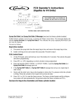
Figure 5-1
Symbol Definitions
To better communicate in the international arena,
symbols have replaced words on many of our operator
switches, function, and fault indicators. Your Taylor
equipment is designed with these international symbols.
The following chart identifies the symbol definitions.
2
3
4
5
1
6
Item
Description
1 Product Light—Left Side
2 Control Switch
3 Keypad—Left Side
4 Liquid Crystal Display
5 Keypad—Right Side
6 Product Light—Right Side
= OFF
=ON

5-2
USER INTERFACE
Model C300NP
User Interface
5
Control Switch
The control switch is located at the top left corner of the
control channel. When placed in the ON position,
SLUSHTECH is able to operate.
Liquid Crystal Display
The liquid crystal display (LCD) is located on the front
control panel. The LCD is used to show the current
operating mode of the freezing cylinders. The LCD also
indicates whether there is enough syrup, CO
2
, and water
being supplied to the freezer. If an error in the machine
operation occurs, a warning tone will sound and the word
FAULT will flash on the third line of the display.
Operational Mode Display
The following displays illustrate the Operational Mode
Displays. This information appears on the LCD during
normal operation.
When the unit is plugged into the wall receptacle and the
control switch is in the ON position, this screen appears.
This display will remain on the LCD for 60 seconds
unless a key is pressed. If any key is pressed (or 60
seconds pass), then the next screen appears.
Note: Syrup, CO
2,
and water are satisfied.
Pressing the AUTO (- ->) keys on both sides of the unit
will display this screen.
Line 1 indicates the operating mode for each freezing
cylinder.
Line 2 indicates the status of the syrup systems in each
freezing cylinder. As long as syrup is available, the word
OK will appear on the LCD. When the syrup supply is
insufficient, the word OUT will flash on the LCD. The
same rules apply to the fourth line, which indicates the
status of the CO
2
and the H
2
O.
The third line of this display is a fault indicator. If an error
in machine operation occurs, the word FAULT will be
displayed on the LCD.
Operator Menu Display
The OPERATOR MENU is used to enter into the
operating screens. To access the OPERATOR MENU,
simply press the MENU (SEL) key. The cursor will flash
under the letter A, indicating that this is screen A. To
select a different screen, use the AUTO (- ->) and OFF
(<- -) keys to move the cursor to the desired screen
selection and press the MENU (SEL) key.
Operator Menu Timeout
If the display is left in the operator menu or any of the
operator menu selections, except for Current Conditions,
the display will return to the system mode screen 60
seconds after the last key press. The Current Conditions
screen will be displayed until manually changed.
Finding Current Fault Conditions
Screen B is FAULT DESCRIPTION.
The fault description will indicate if there is a fault in one
of the freezing cylinders. When the actual fault is
corrected, the warning tone will stop. Only BRL NOT
COOLING requires pressing the OFF (<- -) key to clear
the fault message and the warning tone.
SAFETY TIMEOUT
ANY KEY ABORT
OFF MODE OFF
OK SYRUP OK
KO-RETAWKO-2OC
AUTO MODE AUTO
OK SYRUP OK
KO-RETAWKO-2OC
BEATER MODE BEATER
OUT SYRUP OUT
--TLUAF----TLUAF--
TUO-O2HTUO-2OC
OPERATOR MENU
A
BCDEFGHI
EXIT MENU
LES>----<
/