Page is loading ...

GT15M-TH Transducer
Installation Instructions
Important Safety Information
WARNING
See the Important Safety and Product Information guide in the
chartplotter or fishfinder product box for product warnings and
other important information.
The device must be installed with at least one of the included
anti-rotation bolts. Failure to do so could result in the device
rotating while the boat is moving and could cause damage to
your vessel.
You are responsible for the safe and prudent operation of your
vessel. Sonar is a tool that enhances your awareness of the
water beneath your boat. It does not relieve you of the
responsibility of observing the water around your boat as you
navigate.
CAUTION
Failure to install and maintain this equipment in accordance with
these instructions could result in damage or injury.
Always wear safety goggles, ear protection, and a dust mask
when drilling, cutting, or sanding.
NOTICE
When drilling or cutting, always check what is on the opposite
side of the surface.
To obtain the best performance and to avoid damage to your
boat, you must install the Garmin
®
device according to these
instructions.
Read all installation instructions before proceeding with the
installation. If you experience difficulty during the installation,
contact Garmin Product Support.
Registering Your Device
Help us better support you by completing our online registration
today.
• Go to my.garmin.com/registration.
• Keep the original sales receipt, or a photocopy, in a safe
place.
Software Update
You may need to update the device software when you install
the device or add an accessory to the device.
This device supports up to a 32 GB memory card, formatted to
FAT32.
Loading the New Software on a Memory Card
You must copy the software update to a memory card using a
computer that is running Windows
®
software.
NOTE: You can contact Garmin customer support to order a
preloaded software update card if you do not have a computer
with Windows software.
1
Insert a memory card into the card slot on the computer.
2
Go to garmin.com/support/software/marine.html.
3
Select Download next to the software bundle that
corresponds with your chartplotter.
NOTE: The software download includes updates for all
devices connected to the chartplotter. Select the correct
bundle that corresponds to the chartplotter to be updated.
You can select See All Devices in this Bundle to confirm the
devices included in your download.
4
Read and agree to the terms.
5
Select Download.
6
If necessary, select Run.
7
If necessary, select the drive associated with the memory
card, and select Next > Finish.
8
Extract the files to the memory card.
NOTE: The software update can take several minutes to load
onto the memory card.
Updating the Device Software
Before you can update the software, you must obtain a
software-update memory card or load the latest software onto a
memory card.
1
Turn on the chartplotter.
2
After the home screen appears, insert the memory card into
the card slot.
NOTE: In order for the software update instructions to
appear, the device must be fully booted before the card is
inserted.
3
Follow the on-screen instructions.
4
Wait several minutes while the software update process
completes.
5
When prompted, leave the memory card in place and restart
the chartplotter manually.
6
Remove the memory card.
NOTE: If the memory card is removed before the device
restarts fully, the software update is not complete.
Mounting Considerations
• On a boat with more than a 5° deadrise angle, a fairing block
will need to be fabricated (not available for sale).
• On a boat with a 12° deadrise angle, the transducer with a
fairing block can accommodate a hull up to 29 mm (1.15 in.)
thick.
• On a boat with a 20° deadrise angle, the transducer with a
fairing block can accommodate a hull up to 19 mm (
3
/
4
in.)
thick.
• On displacement hull vessels, the transducer should be
mounted near the centerline.
• On planing hull vessels, the transducer should be mounted
aft, on or near the centerline, inboard of the first set of lifting
strakes.
• On displacement hull and planing hull vessels, the transducer
should be mounted on the starboard side of the hull where
the propeller blades are moving downward.
• On stepped hull vessels, the transducer should be mounted
directly in front of the first step.
April 2017
190-02161-02 _0B

• On fin-keel vessels, the transducer should be mounted more
than 300 mm (12 in.) and less than 600 mm (24 in.) in front of
the keel and on or near the centerline.
• On full-keel vessels, the transducer should be mounted in the
center of the ship, away from the keel at the point of
minimum deadrise.
• On single-drive vessels, the transducer must not be mounted
in the path of the propeller.
• On twin-drive vessels, the transducer should be mounted
between the drives, if possible.
• The transducer must be mounted on a flat location at less
than 6° of deadrise angle.
• The transducer should be mounted well ahead of the
propellers and shafts.
• The transducer should be mounted in a location where it is
vertical when the boat is underway. If the transducer leans
forward, the marine bottom can appear to slope upward. If
the transducer leans aft, some surface clutter may appear.
• The transducer should be mounted more than 600 mm
(24 in.) from other transducers.
• The transducer should be mounted in a location that is
unobstructed by the keel or propeller shafts.
• The transducer must be mounted in a location where it is
continuously immersed in water.
• The transducer should be mounted in a location that allows
accessibility to the transducer from the inside of the vessel.
• The transducer should not be mounted behind strakes, struts,
fittings, water intake or discharge ports, or anything that
creates air bubbles or causes the water to become turbulent.
• The transducer should not be mounted in a location where it
might be jarred when launching, hauling, or storing.
• The transducer can cause cavitation that can degrade the
performance of the boat and damage the propeller.
• The transducer must be in clean (non-turbulent) water for
optimal performance.
• If you have a question about the location of the thru-hull
transducer, contact your vessel builder or other owners of
similar vessels for advice.
Tools Needed
• Drill and 3 mm (
1
/
8
in.) bit
• 25 mm (1 in.) hole saw (fiberglass hull)
• 32 mm (1
1
/
4
in.) hole saw (metal hulls)
• Sandpaper
• Masking tape
• Marine sealant
• Slip-joint pliers (metal hulls)
• Metal file (metal hulls)
• Epoxy or exposed core sealant (cored fiberglass hulls)
• Fiberglass cloth and resin (option for sealing a cored-
fiberglass hull)
• Cable ties
Cored Fiberglass Boat Hull Installation
Instructions
Drilling a Hole in a Cored-Fiberglass Hull
1
From inside the boat, drill a 3 mm (
1
/
8
in.) pilot hole
completely through the hull.
2
Examine the pilot hole on the outside of the boat, and select
an option:
• If the pilot hole is not in the correct location, seal the hole
with epoxy and repeat step 1.
• If the pilot hole is in the correct location, use a 25 mm (1
in.) hole saw to cut a hole from the outside of the boat
through the outer fiberglass skin only. Do not cut
completely through the hull.
3
On the inside of the boat, at the pilot hole location, use a hole
saw to cut a hole 9 to 12 mm (
3
/
8
to
1
/
2
in.) larger than the
hole you cut in the outside of the boat in step 2.
Cut through the inner fiberglass skin and most of the core,
without cutting the outer skin.
NOTE: When cutting the inner fiberglass skin and core, be
careful to not cut the outer fiberglass skin, or you will not be
able to correctly seal the hull.
4
Remove the inner fiberglass skin and core you cut in step 3.
You should be able to see the inside of the outer fiberglass
skin.
5
Sand the inside of the hole and the areas immediately around
both the inside and outside fiberglass skin.
6
Clean the area using a mild detergent or weak solvent, such
as isopropyl alcohol, to remove any dust and dirt.
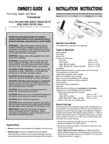
Preparing a Cored-Fiberglass Hull
NOTICE
If the core of a cored-fiberglass hull is not sealed properly, water
may seep into the core and severely damage the boat.
À
Fiberglass or casting epoxy (not included)
Á
Cylinder spacer (included bushing)
Â
Inner fiberglass skin
Ã
Core
Ä
Outer fiberglass skin
1
Drill the hole through the hull.
2
Seal the core inside the hull using either fiberglass (Sealing
the Core with Fiberglass, page 3) or casting epoxy
(Sealing the Core with Casting Epoxy, page 3).
2

Sealing the Core with Fiberglass
1
From inside the boat, coat a layer of fiberglass cloth with
fiberglass resin and place it inside the hole to seal the core.
2
Add layers of fiberglass cloth and resin until the hole is
25 mm (1 in.) in diameter.
3
After the fiberglass has hardened, sand and clean inside and
around the hole.
The cored-fiberglass hull is now prepared, and you can
complete the transducer installation.
Sealing the Core with Casting Epoxy
1
Coat the included 25 mm (1 in.) cylinder with wax.
2
From outside the boat, insert the cylinder into the hole, and
tape it in place on the outer surface.
3
Fill the space between the cylinder and the core with casting
epoxy.
4
After the epoxy has hardened, remove the cylinder, sand and
clean inside and around the hole.
The cored-fiberglass hull is prepared, and you can complete
the transducer installation.
Applying Marine Sealant to a Thru-hull Transducer
You must apply marine sealant to the water path to ensure a
tight, waterproof seal between the transducer and hull.
Apply a 2 mm (
1
/
16
in.) layer of marine sealant to the flange of
the housing that will contact the hull, and up the sidewall of
the housing.
NOTE: The sealant must extend 6 mm (
1
/
4
in.) above the top
of the hull to seal the hull and secure the hull nut.
Installing the Transducer in a Fiberglass Hull
It is recommended that two installers complete these
instructions, with one positioned outside the boat and one inside
the boat.
NOTE: When installing a transducer in a fiberglass hull, avoid
over-tightening the nuts to prevent damaging the hull.
1
From outside the hull, insert the transducer
À
through the
mounting hole, using a twisting motion to squeeze out excess
sealant.
2
From inside the hull
Á
, slide the rubber washer
Â
, nylon
washer
Ã
, and hull nut
Ä
onto the stem.
3
Use slip-joint pliers or a crescent wrench to hold the stem,
and secure the hull nut to the transducer stem.
Do not over-tighten the hull nut.
4
Before the sealant hardens, remove all excess sealant on the
outside of the exterior hull to ensure smooth water flow over
the transducer.
Non-cored/Fiberglass/Wooden Boat Hull
Installation Instructions
Drilling a Hole in a Non-Cored Hull
1
Select a mounting location (Mounting Considerations,
page 1).
2
Drill a 3 mm (
1
/
8
in.) pilot hole from outside the hull.
3
If the vessel has a fiberglass hull, place masking tape over
the pilot hole and surrounding area outside the hull to prevent
damage to the fiberglass.
4
If you taped over the pilot hole, use a utility knife to cut out
the hole in the tape.
5
While holding a 25 mm (1 in.) spade bit plumb, cut a hole
from outside the hull at the stem hole location.
6
Sand and clean the area around the hole.
Applying Marine Sealant to a Thru-hull Transducer
You must apply marine sealant to the water path to ensure a
tight, waterproof seal between the transducer and hull.
Apply a 2 mm (
1
/
16
in.) layer of marine sealant to the flange of
the housing that will contact the hull, and up the sidewall of
the housing.
NOTE: The sealant must extend 6 mm (
1
/
4
in.) above the top
of the hull to seal the hull and secure the hull nut.
Installing the Transducer in a Fiberglass Hull
It is recommended that two installers complete these
instructions, with one positioned outside the boat and one inside
the boat.
NOTE: When installing a transducer in a fiberglass hull, avoid
over-tightening the nuts to prevent damaging the hull.
1
From outside the hull, insert the transducer
À
through the
mounting hole, using a twisting motion to squeeze out excess
sealant.
2
From inside the hull
Á
, slide the rubber washer
Â
, nylon
washer
Ã
, and hull nut
Ä
onto the stem.
3
Use slip-joint pliers or a crescent wrench to hold the stem,
and secure the hull nut to the transducer stem.
Do not over-tighten the hull nut.
4
Before the sealant hardens, remove all excess sealant on the
outside of the exterior hull to ensure smooth water flow over
the transducer.
Metal Boat Hull Installation Instructions
Drilling a Hole in a Metal Hull
1
Select a mounting location (Mounting Considerations,
page 1).
2
From outside the hull, drill a 3 mm (
1
/
8
in.) pilot hole through
the hull.
The hole must be perpendicular to the water surface.
3
Using a 32 mm (1
1
/
4
in.) hole saw, cut the stem hole from
outside the hull.
4
Sand and clean the area around the holes.
Applying Marine Sealant to a Thru-hull Transducer in
a Metal Hull
You must apply marine sealant to the water path to ensure a
tight, waterproof seal between the transducer and hull.
1
Apply a 2 mm (
1
/
16
in.) layer of marine sealant to the flange of
the housing that will contact the hull, and up the sidewall of
the housing.
3

NOTE: The sealant must extend 6 mm (
1
/
4
in.) above the top
of the hull to seal the hull and secure the hull nut.
2
Slide the isolation plate and bushing onto the stem, and apply
sealant to the surfaces of the plate and bushing that will
contact the hull. Fill the cavities in and around the plate and
bushing.
Installing the Transducer in a Metal Hull
It is recommended that two installers complete these
instructions, with one positioned outside the boat and one inside
the boat.
1
From outside the hull, insert the transducer
À
through the
isolation plate
Á
and bushing
Â
.
2
Insert the transducer with plate and bushing through the
mounting hole, using a twisting motion to squeeze out excess
sealant.
3
If necessary, trim the bushing.
NOTE: The bushing must be below the hull nut when
installed.
4
From inside the hull
Ã
, slide the rubber washer
Ä
, nylon
washer
Å
, and hull nut
Æ
onto the stem.
5
Use slip-joint pliers or a crescent wrench to hold the stem,
and secure the hull nut to the transducer stem.
Do not over-tighten the hull nut.
6
Before the sealant hardens, remove all excess sealant on the
outside of the exterior hull to ensure smooth water flow over
the transducer.
Maintenance
Testing the Installation
NOTICE
You should check your boat for leaks before you leave it in the
water for an extended period of time.
Because water is necessary to carry the sonar signal, the
transducer must be in the water to work properly. You cannot
get a depth or distance reading when out of the water. When
you place your boat in the water, check for leaks around any
screw holes that were added below the water line.
Anti-Fouling Paint
To prevent corrosion on metal hulls and to slow the growth of
organisms that can affect a vessel's performance and durability,
you should apply a water-based anti-fouling paint to the hull of
your vessel every six months.
NOTE: Never apply ketone-based anti-fouling paint to your
vessel, because ketones attack many types of plastic and could
damage or destroy your transducer.
Cleaning the Transducer
Aquatic fouling accumulates quickly and can reduce your
device's performance.
1
Remove the fouling with a soft cloth and mild detergent.
2
If the fouling is severe, use a scouring pad or putty knife to
remove growth.
3
Wipe the device dry.
Specifications
Specification Measurement
Frequencies* From 80 to 160 kHz
Maximum depth** 549 m (1800 ft.)
Transmit power 600 W
Operating temperature range From 0° to 50°C (from 32° to 122°F)
Storage temperature range From -40° to 70°C (from -40° to 158°F)
*Dependent upon the chartplotter or fishfinder model.
**Dependent upon water conditions.
© 2017 Garmin Ltd. or its subsidiaries
Garmin
®
and the Garmin logo are trademarks of Garmin Ltd. or its subsidiaries,
registered in the USA and other countries.
Panoptix
™
is a trademark of Garmin Ltd. or its
subsidiaries. These trademarks may not be used without the express permission of
Garmin.
/