Miller KC289996 Owner's manual

Category
Welding System
Type
Owner's manual

This manual is also suitable for

cover 8/92 Ref. ST-151 666 / ST-145 432-A PRINTED IN USA
Read and follow these instructions and all
safety blocks carefully.
Have only trained and qualified persons
install, operate, or service this unit.
Call your distributor if you do not understand
the directions.
Give this manual to the operator.
For help, call your distributor
or: MILLER ELECTRIC Mfg. Co., P.O. Box
1079, Appleton, WI 54912 414-734-9821
OWNER’S
MANUAL
October 1992 Form: OM-1581C
Effective With Serial No. KC289996
115 Volts AC Wire Feeder And 30 Volts DC Gun
For GMAW Welding
For Use With CV Or CC Welding Power Source
70-875 ipm (1.9-22.2 mpm) Wire Feed Speed Range
For .030-1/16 in Aluminum And .030-.045 in Hard Or Cored Wire
Air Or Water Cooled Models Available
Control Circuit And Motor Overload Protection
XR A And XR W
OM-1581C 10/92
TABLE OF CONTENTS
SECTION 1 SAFETY INFORMATION 1. . . . . . . . . . . . . . . . . . . . . . . . . . . . . . . . . . . . . . . . . . . . . . . . . . . . .
SECTION 2 SPECIFICATIONS
2-1. Duty Cycle 2. . . . . . . . . . . . . . . . . . . . . . . . . . . . . . . . . . . . . . . . . . . . . . . . . . . . . . . . . . . . . . . . . . . .
SECTION 3 INSTALLATION
3-1. Equipment Connection Diagrams 3. . . . . . . . . . . . . . . . . . . . . . . . . . . . . . . . . . . . . . . . . . . . . . . . .
3-2. Removing Top Cover Of Gun 5. . . . . . . . . . . . . . . . . . . . . . . . . . . . . . . . . . . . . . . . . . . . . . . . . . . .
3-3. Gun To Feeder Connections 6. . . . . . . . . . . . . . . . . . . . . . . . . . . . . . . . . . . . . . . . . . . . . . . . . . . . .
3-4. Internal Connections To Feeder 8. . . . . . . . . . . . . . . . . . . . . . . . . . . . . . . . . . . . . . . . . . . . . . . . . .
3-5. Adjusting Contact Tube Position 10. . . . . . . . . . . . . . . . . . . . . . . . . . . . . . . . . . . . . . . . . . . . . . . . .
3-6. Voltage Sensing Lead Connections 10. . . . . . . . . . . . . . . . . . . . . . . . . . . . . . . . . . . . . . . . . . . . . . .
3-7. 115 VAC/Contactor Control Plug Information 11. . . . . . . . . . . . . . . . . . . . . . . . . . . . . . . . . . . . . . .
3-8. Replacing 115 VAC/Contactor Control Plug With Supplied 5-Pin Or Twistlock Plug 12. . . . . .
3-9. Installing Wire Spool 13. . . . . . . . . . . . . . . . . . . . . . . . . . . . . . . . . . . . . . . . . . . . . . . . . . . . . . . . . . . .
3-10. Threading Welding Wire 14. . . . . . . . . . . . . . . . . . . . . . . . . . . . . . . . . . . . . . . . . . . . . . . . . . . . . . . .
3-11. Coolant Guidelines 15. . . . . . . . . . . . . . . . . . . . . . . . . . . . . . . . . . . . . . . . . . . . . . . . . . . . . . . . . . . . .
SECTION 4 OPERATION 16. . . . . . . . . . . . . . . . . . . . . . . . . . . . . . . . . . . . . . . . . . . . . . . . . . . . . . . . . . . . . . .
SECTION 5 MAINTENANCE & TROUBLESHOOTING
5-1. Routine Maintenance 21. . . . . . . . . . . . . . . . . . . . . . . . . . . . . . . . . . . . . . . . . . . . . . . . . . . . . . . . . . .
5-2. Changing Or Cleaning Gun Drive Roll 22. . . . . . . . . . . . . . . . . . . . . . . . . . . . . . . . . . . . . . . . . . . . .
5-3. Changing Feeder Drive Roll And Wire Inlet Guide 23. . . . . . . . . . . . . . . . . . . . . . . . . . . . . . . . . .
5-4. Replacing Or Cleaning Gun Drive Roll Bearing 24. . . . . . . . . . . . . . . . . . . . . . . . . . . . . . . . . . . . .
5-5. Replacing Or Cleaning Feeder Drive Roll Bearing 24. . . . . . . . . . . . . . . . . . . . . . . . . . . . . . . . . .
5-6. Changing Gun Contact Tube And Liner 25. . . . . . . . . . . . . . . . . . . . . . . . . . . . . . . . . . . . . . . . . . .
5-7. Replacing Contact Tube Adapter 25. . . . . . . . . . . . . . . . . . . . . . . . . . . . . . . . . . . . . . . . . . . . . . . . .
5-8. Replacing Hub Assembly 26. . . . . . . . . . . . . . . . . . . . . . . . . . . . . . . . . . . . . . . . . . . . . . . . . . . . . . .
5-9. Adjusting Hub Tension 27. . . . . . . . . . . . . . . . . . . . . . . . . . . . . . . . . . . . . . . . . . . . . . . . . . . . . . . . . .
5-10. Overload Protection 27. . . . . . . . . . . . . . . . . . . . . . . . . . . . . . . . . . . . . . . . . . . . . . . . . . . . . . . . . . . .
5-11. Water Flow Switch (Optional For Water-Cooled Models) 28. . . . . . . . . . . . . . . . . . . . . . . . . . . . .
5-12. Troubleshooting 28. . . . . . . . . . . . . . . . . . . . . . . . . . . . . . . . . . . . . . . . . . . . . . . . . . . . . . . . . . . . . . .
SECTION 6 ELECTRICAL DIAGRAMS 30. . . . . . . . . . . . . . . . . . . . . . . . . . . . . . . . . . . . . . . . . . . . . . . . . . .
SECTION 7 PARTS LIST
Figure 7-1. Main Assembly 34. . . . . . . . . . . . . . . . . . . . . . . . . . . . . . . . . . . . . . . . . . . . . . . . . . . . . . . . . . . .
Figure 7-2. Motor & Wire Drive 37. . . . . . . . . . . . . . . . . . . . . . . . . . . . . . . . . . . . . . . . . . . . . . . . . . . . . . . . .
Figure 7-3. Panel, Front w/Components (XR-W Model Illustrated) 38. . . . . . . . . . . . . . . . . . . . . . . . . . .
Figure 7-4. Exploded View Of Gun 40. . . . . . . . . . . . . . . . . . . . . . . . . . . . . . . . . . . . . . . . . . . . . . . . . . . . .
OM-1581 Page 1
SECTION 1 SAFETY INFORMATION
mod1.1 8/92
Read all safety messages throughout this manual.
Obey all safety messages to avoid injury.
Learn the meaning of WARNING and CAUTION.
1 Safety Alert Symbol
2 Signal Word
WARNING means possible death
or serious injury can happen.
CAUTION means possible minor
injury or equipment damage can
happen.
3 Statement Of Hazard And
Result
4 Safety Instructions To Avoid
Hazard
5 Hazard Symbol (If Available)
6 Safety Banner
Read safety blocks for each sym-
bol shown.
7 NOTE
Special instructions for best oper-
ation not related to safety.
2
NOTE
ELECTRIC SHOCK can kill.
Do not touch live electrical parts.
Disconnect input power before
installing or servicing.
WARNING
READ SAFETY BLOCKS at start of
Section 3-1 before proceeding.
WARNING
5
4
6
7
1 2
CAUTION
MOVING PARTS can injure.
Keep away from moving parts.
Keep all panels and covers closed
when operating.
3
Turn OFF switch when using high frequency.
Figure 1-1. Safety Information
SECTION 2 SPECIFICATIONS
Table 2-1. Wire Feeder
Specification Description
Type Of Input Power 115 Volts AC, 3 Amperes At 50/60 Or 100 Hz Power
Control Circuit Voltage Provided At Gun 30 Volts DC
Wire Feed Speed Range 70-875 ipm (1.9-22.2 mpm)
Overall Dimensions Length: 19 in (483 mm); Width: 9-1/4 in (235 mm); Height: 15-1/4 in (387 mm)
Maximum Spool Capacity 12 in (305 mm)
Cooling Method Air-Cooled (A Models) Or Water-Cooled (W Models)
Weight (Feeder With Gun) Models With 15 ft (4.6 m) Cable Assembly
Net: 56 lb (25 kg); Ship: 58 lb (26 kg)
Models With 30 ft (9.1 m) Cable Assembly
Net: 63 lb (29 kg); Ship: 65 lb (30 kg)
Table 2-2. Gun
Specification Description
Input Voltage 30 Volts DC
Duty Cycle (Air-Cooled Models) At 200 Amperes, 100% Using Argon Or Argon Mixture Shielding Gas
At 250 Amperes, 60% Using Argon Or Argon Mixture Shielding Gas (See Sec-
tion 2-1)
Duty Cycle (Water-Cooled Models) At 400 Amperes, 100% Using Argon Or Argon Mixture Shielding Gas (See
Section 2-1)
Wire Size Range .030 Thru 1/16 in (0.8 Thru 1.6 mm) Aluminum Wire
.030 Thru .045 in (0.8 Thru 1.1 mm) Hard Or Cored Wire
OM-1581 Page 2
2-1. Duty Cycle
CAUTION
USING GUN BEYOND DUTY CYCLE RATING can damage gun.
Do not exceed indicated duty cycles.
Duty cycle is how long the gun can operate within a ten minute period without causing overheating or damage. Both
models are rated using argon or argon mixture shielding gas.
The air-cooled model is rated at 100% duty cycle when operated at 200 amperes, allowing continuous welding. When
operated at 250 amperes, the air-cooled model is rated at 60% duty cycle, allowing welding 6 minutes out of every 10
minutes.
The water-cooled model is rated at 100% duty cycle when operated at 400 amperes, allowing continuous welding.
SECTION 3 INSTALLATION
Table 3-1. Items Included With Feeder And Gun
Item Quantity
Feeder Drive Roll (Small Groove For .030 Thru .035 in
Wire, Large Groove For .047 Thru 1/16 in Wire) Shipped
With Large Groove In Feed Position
1
Gun Drive Roll* (Small Groove For .025 Thru .035 in Wire,
Large Groove For .047 Thru 1/16 in Wire) Shipped With
Large Groove In Feed Position
1
Contact Tubes (1 For Each Wire Size .023/.025, .030,
.035, .047, And 1/16 in) Shipped With .047 Installed
5
10 ft (3 m) Gas Hose 1
10 ft (3 m) Water Hose With Adapter Fitting (Water-Cooled
Models Only)
1
10 ft (3 m) Water Hose (Water-Cooled Models Only) 1
Contact Tube Wrench 1
5-Pin Plug 1
Two-Prong Twistlock Plug 1
*A .023/.025 contact tube is supplied with gun, but feeder is not designed to feed
these wire sizes.
Be sure that contact tube, liner, and drive rolls are correct for wire size and type,
see Section 5 to change parts as needed. See Section 7 for list of other available
contact tubes.
NOTE
OM-1581 Page 3
3-1. Equipment Connection Diagrams
CYLINDERS can explode if damaged.
Keep cylinders away from welding and other
electrical circuits.
Never touch cylinder with welding electrode.
Always secure cylinder to running gear, wall, or
other stationary support.
HOT SURFACES can burn skin.
Allow gun to cool before touching.
ELECTRIC SHOCK can kill.
Do not touch live electrical parts.
Turn OFF wire feeder and welding power source,
and disconnect input power before making
connections.
The welding wire, drive rolls, drive assembly, and all
metal parts touching the welding wire are electrically
live when welding or feeding wire using gun trigger.
Have only qualified persons install this unit.
WARNING
wfwarn7.1* 9/91
Review Figure 3-1 through Figure 3-4 to determine how equipment will be connected. Air-cooled models are shown in
Figure 3-1 through Figure 3-4. For water-cooled models, supplied water hoses must be connected from wire feeder to
coolant supply.
Read entire Section 3 before installing equipment.
1 CV Or CC/CV Welding Power
Source
2 115 VAC/Contactor Control
14-Pin Plug PLG5
3 Positive (+) Weld Cable
4 Negative () Weld Cable
5 Workpiece
6 Voltage Sensing Lead
Connect lead to workpiece for CC
welding only.
7 Gun
8 Wire Feeder
9 10 ft (3 m) Gas Hose
10 115 VAC/Contactor Control
Cord
11 Gas Cylinder
ST-151 774
1
2
3
4
5
6
7
8
9
10
11
Figure 3-1. Connections With A Constant Voltage (CV) Or Constant Voltage/Constant Current (CV/CC)
Welding Power Source Having A 14-Socket Receptacle
OM-1581 Page 4
1 CV Welding Power Source
2 Plug
Obtain matching plugs for connect-
ing to power source receptacles.
3 Positive (+) Weld Cable
4 Negative () Weld Cable
5 Workpiece
6 Voltage Sensing Lead
Do not connect to workpiece.
7 Gun
8 Wire Feeder
9 10 ft (3 m) Gas Hose
10 115 VAC/Contactor Control
Cord
11 Gas Cylinder
ST-151 775-A
1
2
3
4
5
6
7
8
9
10
11
Figure 3-2. Connections With A Constant Voltage (CV) Welding Power Source Having Separate 115 VAC
And Contactor Control Receptacles
1 CC Welding Power Source
2 5-Pin Or Two-Prong Twistlock
Plug (Supplied)
3 Positive (+) Weld Cable
4 Negative () Weld Cable
5 Workpiece
6 Voltage Sensing Lead
7 Gun
8 Wire Feeder
9 10 ft (3 m) Gas Hose
10 2-Conductor Contactor Con-
trol Cord
11 3-Conductor 115 VAC Cord
12 Gas Cylinder
13 115 VAC Plug
Obtain plug for wire feeder.
ST-151 776
1
2
3
4
5
6
7
8
9
10
12
11
13
Figure 3-3. Connections With A Constant Current (CC) Welding Power Source Having Contactor
Control Receptacle
OM-1581 Page 5
1 CC Welding Power Source
2 Positive (+) Weld Cable
3 Negative () Weld Cable
4 Workpiece
5 Voltage Sensing Lead
6 Gun
7 Wire Feeder
8 10 ft (3 m) Gas Hose
9 3-Conductor 115 VAC Cord
10 2-Conductor Contactor Con-
trol Cord
11 5-Pin Plug (Supplied)
12 Secondary Contactor
13 Gas Cylinder
14 115 VAC Plug
Obtain plug for wire feeder.
ST-151 777
1
2
3
4
5
6
7
8
9
13
10
14
2
11
12
Figure 3-4. Connections With A Constant Current (CC) Welding Power Source And A 115VAC/12VDC
Secondary Contactor
3-2. Removing Top Cover Of Gun
1 Top Cover
Push back and lift off as shown.
To reinstall cover, set rear of cover
in gun, and push cover back, down,
and forward until it clicks into posi-
tion.
Ref. ST-150 882-A
1
Figure 3-5. Removing Top Cover Of Gun
OM-1581 Page 6
3-3. Gun To Feeder Connections
WARNING
ELECTRIC SHOCK can kill.
Do not touch live electrical parts.
Turn OFF wire feeder and welding power source, and disconnect input power before inspecting or installing. Stop engine on
welding generator.
wfwarn1.1 9/91
A. Air-Cooled Gun Connections
3
1 Gun Control Cable
Insert plug into GUN CONTROL
receptacle, and tighten threaded
collar.
2 Gas Hose
Connect to GAS fitting on feeder.
3 Weld Cable
4 Weld Cable Terminal In
Feeder
Connect gun weld cable to weld
cable terminal in feeder.
5 Wire Conduit
6 Thumbscrew
7 Wire Conduit Block
Loosen thumbscrew, and insert
conduit through WIRE opening un-
til it bottoms against block. Tighten
thumbscrew. Close and latch door.
Ref. ST-151 778-A / ST-151 666 / ST-145 432-A
Tools Needed:
5/8 in, 3/4 in
4
3
7
6 5
1
2
5
Left Side
Figure 3-6. Air-Cooled Gun Connections
OM-1581 Page 7
B. Water-Cooled Gun Connections
READ SAFETY BLOCKS at start of
Section 3-3 before proceeding.
WARNING
1 Gas Hose
Connect to GAS fitting on feeder.
2 Water Hose
Connect to WATER TO GUN fitting
on feeder (left-hand threads).
3 Wire Conduit
4 Thumbscrew
5 Wire Conduit Block
Loosen thumbscrew, and insert
conduit through WIRE opening un-
til it bottoms against block. Tighten
thumbscrew.
6 Gun Control Cable
Insert plug into GUN CONTROL
receptacle, and tighten threaded
collar.
7 Strain Relief
Remove strain relief as shown.
8 Power/Water Cable
Route cable through strain relief
and connect to WELD/WATER
FROM GUN outlet on feeder. Rein-
stall strain relief. Close and latch
door.
Ref. ST-151 778-A / ST-152 456
1
2
3
6
8
7
43
5
5/8 in, 1-1/8 in
Tools Needed:
Left Side
Figure 3-7. Water-Cooled Gun Connections
OM-1581 Page 8
3-4. Internal Connections To Feeder
ELECTRIC SHOCK can kill.
Do not touch live electrical parts.
Turn OFF wire feeder and welding power source,
and disconnect input power before inspecting or
installing. Stop engine on welding generator.
The welding wire, drive rolls, drive assembly, and all
metal parts touching the welding wire are electrically
live when welding or feeding wire using gun trigger.
CYLINDERS can explode if damaged.
Keep cylinders away from welding and other
electrical circuits.
Never touch cylinder with welding electrode.
Always secure cylinder to running gear, wall, or
other stationary support.
HIGH GAS PRESSURE can cause gun
gas valve to leak.
Do not use gas pressure above 50 psi (345 kPa) or
mechanical gas valve in gun can leak.
OVERHEATING can damage gun parts.
If using recirculating coolant system, do not make
connections from coolant system to water valve;
instead make connections directly from coolant
system to gun hoses.
INCORRECT COOLANT FLOWRATE
can damage gun parts.
Maintain minimum 1 qt/min flowrate at all times.
WARNING
wfwarn7.1* 9/91
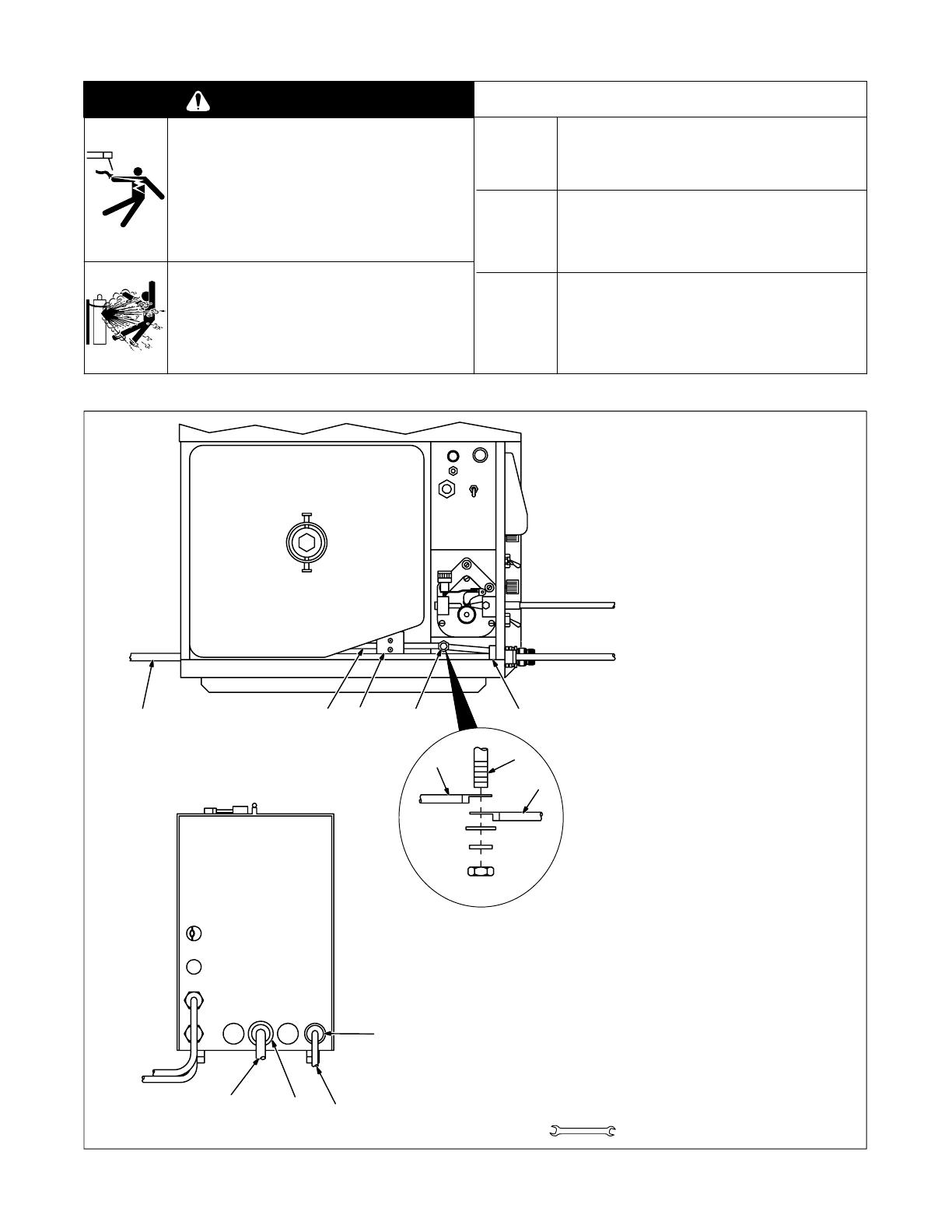
A. Air-Cooled Feeder Connections
1 Gas Hose Grommet
2 10 ft (3 m) Gas Hose
3 Rear Of Gas Fitting
Route one end of gas hose through
grommet, and connect hose to rear
of GAS fitting in feeder. Connect re-
maining end of hose to regulator/
flowmeter.
4 Weld Cable To Welding Power
Source
Select and prepare weld cable ac-
cording to welding power source
manual.
5 Weld Cable Grommet
6 Reed Switch
7 Weld Cable Terminal In Feeder
Route one end of weld cable through
grommet, through reed switch, and
connect to weld cable terminal in
feeder. Connect remaining end of
cable to positive (+) weld output ter-
minal on welding power source.
8 Gun Weld Cable
Be sure that terminal of welding pow-
er source weld cable is in direct con-
tact with terminal from gun weld
cable. Close and latch door.
Ref. ST-151 771
Tools Needed:
5/8 in, 1-1/8 in
Top View
4
7
8
Connect To
Positive (+) Weld
Output Terminal On
Welding Power Source
Connect To
Regulator/
Flowmeter
1
5
246 7 3
Rear Panel
Figure 3-8. Air-Cooled Feeder Connections
OM-1581 Page 9
B. Water-Cooled Feeder Connections
READ SAFETY BLOCKS at start of
Section 3-4 before proceeding.
WARNING
Obtain coolant supply.
1 Gas Hose Grommet
2 10 ft (3 m) Gas Hose
3 Rear Of Gas Fitting
Route one end of gas hose through
grommet, and connect hose to rear
of GAS fitting in feeder. Connect
remaining end of hose to regulator/
flowmeter.
4 Coolant Supply Hose Grom-
met
5 10 ft (3 m) Water Supply
Hose With 5/8 in Adapter Fit-
ting
6 Rear Of Water Fitting (Left-
Hand Threads)
Remove 5/8 in adapter fitting from
hose. Route one end of a water
hose through grommet, and con-
nect to rear of WATER TO GUN fit-
ting in feeder. Connect remaining
end to supply fitting on coolant sup-
ply.
7 Coolant Return Hose Grom-
met
8 10 ft (3 m) Water Return
Hose
9 Connection Block (Left-Hand
Threads)
Route one end of remaining water
hose through grommet, and con-
nect to rear of connection block
(not shown). Connect remaining
end of hose to return fitting on cool-
ant supply.
10 Weld Cable Grommet
11 Weld Cable To Welding Pow-
er Source
Select and prepare weld cable ac-
cording to welding power source
manual.
12 Current Sensing (Reed)
Relay
13 Weld Cable Screw In Feeder
Route one end of weld cable
through grommet, through reed
switch, and connect to block in
feeder using hardware shown.
Connect remaining end of cable to
positive (+) weld output terminal on
welding power source.
Close and latch door.
Ref. ST-152 431-A
5/8 in, 1-1/8 in
Tools Needed:
141078
Connect To
Return Fitting On
Coolant Supply
Connect To
Positive (+) Weld
Output Terminal On
Welding Power Source
Connect To
Supply FittingOn
Coolant Supply
Connect To
Regulator/
Flowmeter
5
9112312
6
11
Top View
Rear Panel
13
Figure 3-9. Water-Cooled Feeder Connections
OM-1581 Page 10
3-5. Adjusting Contact Tube Position
WARNING
ELECTRIC SHOCK can kill.
Do not touch live electrical parts.
Turn OFF wire feeder and welding power source, and disconnect input power before inspecting or installing. Stop engine on
welding generator.
wfwarn1.1 9/91
1 Contact Tube
2 Nozzle
Adjusting barrel changes contact
tube location from 1/16 in (1.6 mm)
out beyond end of nozzle to 1/4 in
(6.3 mm) inside nozzle.
3 Jam Nut
4 Barrel
To change contact tube location,
loosen jam nut, and turn barrel.
Tighten jam nut.
ST-150 434 / Ref. ST-150 431
1
3
2
1
2
4
3
4
Air Cooled ModelWater Cooled Model
Figure 3-10. Adjusting Contact Tube Position
3-6. Voltage Sensing Lead Connections
WARNING
ELECTRIC SHOCK can kill.
Do not touch live electrical parts.
Turn OFF wire feeder and welding power source,
and disconnect input power before inspecting or
installing. Stop engine on welding generators.
STATIC ELECTRICITY can damage parts
on circuit boards.
Put on grounded wrist strap BEFORE handling
boards or parts.
fwarn5.1* 9/91
Unit is factory set for constant volt-
age (CV) welding. To set unit for
constant current (CC) welding,
proceed as follows:
1 Terminal Strip 2T
2 Strain Relief
Loosen screws of strain relief.
3 Voltage Sensing Lead
Route ring terminal end of lead
through strain relief, and connect
ring terminal to terminal A of termi-
nal strip 2T. Tighten screws on
strain relief.
4 Motor Speed Control Board
PC1
5 Jumper Plug
6 Receptacle RC5
For constant voltage (CV) welding,
place jumper plug in INT. position.
Do not connect voltage sensing
lead clamp to workpiece.
For constant current (CC) welding,
place plug in EXT. position. Con-
nect clamp end of voltage sensing
lead to workpiece.
Reinstall right side panel.
Ref. ST-151 772
Tools Needed:
1/4 in
EDCBA
3
4
EXT INT
RC5
321
6 5
1
3
2
Figure 3-11. Voltage Sensing Lead Connections
OM-1581 Page 11
3-7. 115 VAC/Contactor Control Plug Information
Pin information to connect the following equipment:
Remote Contactor
A,B Contact closure completes the contactor control circuit.
Remote Voltage Control (Optional)
C Command reference; +10 volts dc.
D Remote control circuit common.
E Remote power source voltage command signal from feeder; poten-
tiometer wiper 0 to +10 volts dc.
Remote Contactor
G Circuit common for 115 volts ac circuit.
I 115 volts ac.
J Contact closure to pin I completes 115 volts ac contactor control cir-
cuit.
K Circuit common.
Remaining pins are not used.
1 Interconnecting Cord
2 115 VAC/Contactor Control
Plug PLG5
If CC or CC/CV welding power
source is equipped with matching
14-socket receptacle, insert plug,
and tighten threaded collar. Pro-
ceed to Section 3-9.
If plug PLG5 will not connect to CC
welding power source receptacle,
use the following pin information
and Section 3-8 to replace PLG5
with a suitable plug.
Ref. S-0004-A / Ref. ST-151 772
AJ
B
K
I
C
L
NH
D
M
G
E
F
1
2
Figure 3-12. 115 VAC/Contactor Control Plug Information
OM-1581 Page 12
3-8. Replacing 115 VAC/Contactor Control Plug With Supplied 5-Pin Or Twistlock Plug
ELECTRIC SHOCK can kill.
Do not touch live electrical parts.
Turn OFF wire feeder and welding power source, and disconnect input power before inspecting or installing. Stop engine on
welding generator.
Have only qualified persons make wiring connections.
WARNING
wfwarn1.1* 9/91
1 115 VAC/Contactor Control
Plug PLG5
2 Contactor Control Cord
3 115 VAC Cord
Find and label cords by following
leads to back of PLG5:
Contactor control cord connects to
pins A & B of PLG5
115 VAC cord connects to pin J of
PLG5.
Cut off plug PLG5.
4 5-Pin Plug
5 Two-Prong Twistlock Plug
For connections shown in Figure
3-3 or Figure 3-4, install 5-pin or
twistlock plug onto contactor con-
trol cord.
For Figure 3-2 connection, obtain
plug to match contactor control re-
ceptacle on welding power source,
and install plug onto contactor con-
trol cord.
Obtain 115 VAC plug and connect
to 115 VAC cord as follows:
green lead to ground
white lead to 115VAC common
black lead to 115VAC hot.
6 Plug PLG50
7 Plug PLG51
8 Plug PLG52
Unit shipped with PLG50 con-
nected to PLG51 to provide 115
VAC for contactor.
If contact closure needed for con-
tactor, connect PLG50 to PLG52.
ST-151 773-B
1
Tools Need-
ed:
254
3
8
7
6
Or
Figure 3-13. Replacing 115 VAC/Contactor Control Plug With Supplied 5-Pin Or Twistlock Plug
OM-1581 Page 13
3-9. Installing Wire Spool
Turn OFF wire feeder and welding
power source.
1 Wire Spool
2 Top Cover
3 Pressure Roll Assembly
4 Gun Contact Tube
If wire spool is being replaced, open
pressure roll assembly in gun, and
cut welding wire off at contact tube.
For welding power sources without
contactor, retract wire onto spool.
For welding power sources with a
contactor, energize power source,
turn ON feeder, press Brake Re-
lease button (see Figure 4-11), and
retract wire onto spool.
Close gun pressure roll assembly
and reinstall top cover.
5 Hub
6 Hub Pin
7 Compression Spring (Optional
For 8 in Spool)
8 Retaining Ring
Slide spool onto hub so wire feeds
off bottom. Turn spool until hub pin
fits hole in back of spool. Reinstall
retaining ring.
Thread welding wire (see Section
3-10). Close and latch door.
Ref. ST-151 771 / Ref. ST-072 573-B / Ref. ST-151 599
Tools Needed:
6
5
1
8
2
4
3
7
Figure 3-14. Installing Wire Spool
OM-1581 Page 14
3-10. Threading Welding Wire
ELECTRIC SHOCK can kill.
Do not touch live electrical parts.
The welding wire, drive rolls, drive assembly, and all
metal parts touching the welding wire are electrically
live when welding or feeding wire using gun trigger.
HOT SURFACES can burn skin.
Allow gun to cool before touching.
CYLINDERS can explode if damaged.
Keep cylinders away from welding and other
electrical circuits.
Never touch cylinder with welding electrode.
Always secure cylinder to running gear, wall, or
other stationary support.
WELDING WIRE can cause puncture
wounds.
Do not press gun trigger until instructed to do so.
Do not point gun toward any part of the body, other
people, or any metal when threading welding wire.
WARNING
wfwarn7.1* 9/91
A. Threading Welding Wire Through Feeder
Turn OFF wire feeder and welding
power source.
1 Wire Spool
Loosen wire from spool, cut off
bent wire, and pull 6 in (150 mm) of
wire off spool.
2 Tension Arm
3 Mounting Arm
To open pressure roll assembly,
open tension arm and lift mounting
arm.
4 Wire Inlet Guide
5 Drive Roll
6 Wire Conduit Fitting
Thread wire through wire inlet
guide, along drive roll groove, and
into fitting.
Close and secure pressure roll as-
sembly.
7 Tension Thumbnut
8 Jog Switch
For proper adjustment, loosen
thumbnut until drive roll slips when
JOG switch is pushed up. Grasp
spool with one hand, and turn
thumbnut clockwise until motor
stalls when JOG switch is pushed
up.
Feed welding wire through gun
(see Figure 3-16). Close and latch
door.
Ref. ST-131 328 / Ref. ST-151 778
Tools Needed:
1
3
2
456
8
7
Figure 3-15. Threading Welding Wire Through Feeder
  • Page 1 1
  • Page 2 2
  • Page 3 3
  • Page 4 4
  • Page 5 5
  • Page 6 6
  • Page 7 7
  • Page 8 8
  • Page 9 9
  • Page 10 10
  • Page 11 11
  • Page 12 12
  • Page 13 13
  • Page 14 14
  • Page 15 15
  • Page 16 16
  • Page 17 17
  • Page 18 18
  • Page 19 19
  • Page 20 20
  • Page 21 21
  • Page 22 22
  • Page 23 23
  • Page 24 24
  • Page 25 25
  • Page 26 26
  • Page 27 27
  • Page 28 28
  • Page 29 29
  • Page 30 30
  • Page 31 31
  • Page 32 32
  • Page 33 33
  • Page 34 34
  • Page 35 35
  • Page 36 36
  • Page 37 37
  • Page 38 38
  • Page 39 39
  • Page 40 40
  • Page 41 41
  • Page 42 42
  • Page 43 43
  • Page 44 44
  • Page 45 45
  • Page 46 46
  • Page 47 47
  • Page 48 48
  • Page 49 49
  • Page 50 50
  • Page 51 51
  • Page 52 52
  • Page 53 53
  • Page 54 54

Miller KC289996 Owner's manual

Category
Welding System
Type
Owner's manual
This manual is also suitable for

Ask a question and I''ll find the answer in the document

Finding information in a document is now easier with AI