Page is loading ...

YEid 01
4a
Installation lniiitions and
Use & Care Guide
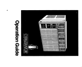
Control panel
Model and
serial number
plate
(not shown)
Air discharge
Control panel
Model and
serial number
plate
AIR CONDITIONERS
Models ACS602XT ACS802XV ACSl02XT ACC602XT
a-s3

Contents
Page
Electrical Requirements. ..........
Receptacle wiring .................
Electrical requirements .............
Electrical connection ..............
Installation Instructions ...........
Installation instructions 1 ...........
Installation instructions 2 ...........
Operating Instructions ............
Starting your air conditioner
.........
The exhaust control ...............
Changing air direction ..............
Cleaning and caring for your
air conditioner ..................
It You Need Service Or Assistance
Whirlpool Room Air Conditioner
Warranty ..........................
3
3
3
3
4
4
8
11
11
11
11
12
15
16
01969 Whirlpool Corporation
Thank you for buying a Whirlpool appliance.
Please complete and mail the Owner
Registration Card provided with this prod-
uct. Then complete the form below. Have this
information ready if you need service or call with
a question.
l
Copy model and serial numbers from plate
(see diagram on page 12) and purchase date
from sales slip.
l
Keep this book and sales slip together in a
handy place.
It is your personal responsibility to be sure
your air conditioner:
l
Has been properly installed.
l
Is the right size for the area you want to cool.
l
Is properly connected and grounded to electrical
supply.
l
Is used only for the job it was intended to do.
l
Is not used by children or anyone unable to
operate it properly.
l
Is properly maintained.
l
Also, remove energy label and buy guide. Use
damp cloth to take off any glue residue. Do not
use a sharp instrument or any harsh or abrasive
cleaners.
Important:
Please read this Use & Care Guide before install-
ing or using your air conditioner. It tells you how to
install and operate it, and gives important electrical
information. Save it for future use in case you have
a question or move the air conditioner.
Personal Injury Hazard
The metal fins on the coils are sharp. Han-
dle the air conditioner with care. Failure to
do so could result in personal injury.
Model Number
Serial Number
Purchase Date
Servlce Company Phone Number
2

Electrical Requirements
Electrical requirements are different for the two
models pictured on the cover, depending on the
ampere rating of your unit. The number of
amperes is printed on the serial plate, which is
attached to the front of the unit behind the front
panel (see diagram on page 12).
Observe all local governing codes and
ordinances.
Do not, under any circumstances, remove
the power supply cord grounding prong.
Receptacle wiring
Receptacle wiring should be a minimum of 14
gauge. Use copper wire only. It is the personal
responsibility of the consumer to provide proper
and adequate receptacle wiring installed by a
qualified electrician. Observe National Electrical
Code and all local governing codes and
ordinances.
Z&prong
Electrical requirements
Electrical Shock Hazard
l
Check with a qualified electrician if you
are in doubt as to whether the appliance is
properly grounded. Do not modify the
power supply cord plug - if it will not fit
the outlet, have a proper outlet installed
by a qualified electrician. Improper
connection of the equipment-grounding
conductor can result
in a risk of
electrical shock.
l
Do not use an extension cord with this
appliance. Such use may result in a fire,
electrical shock or other personal injury.
. Do not have a fuse in the neutral or
grounding circuit. This could result in a
risk of electrical shock.
A 115 volt, 60 Hz AC only, 15 ampere fused elec-
trical supply is required (time delay fuse or time
delay circuit breaker required). It is recommended
that a separate circuit, serving only this appliance,
be provided for models with serial plate amperes
up through 7.5. A separate circuit is required
for models with serial plate amperes of 7.6
through 12.0.
Electrical connection
Electrical ground is required on this appliance.
Recommended grounding method
For your personal safety, this appliance must be
grounded. This air conditioner is equipped with a
power supply cord having a 3-prong grounding
plug. To minimize possible shock hazard, the cord
must be plugged into a mating 3-prong grounding
type wall receptacle, grounded in accordance with
the National Electrical Code, ANSVNFPA 70-1987
(or to the latest), and local codes and ordinances.
If a mating wall receptacle is not available, it is the
personal responsibility of the customer to have a
properly grounded 3-prong wall receptacle
installed by a qualified electrician.
3

Electrical Requirements
Continued
Electrically
grounded metal
cold water pipe
Ground assembly
(attach to grounded
Grounded eyelet
Grounding prong
Temporary grounding method
If changing and properly grounding the wall recep-
tacle is impossible and where local codes permit
(consult your electrical inspector), a temporary
adapter may be plugged into the existing 2-prong
wall receptacle to male with the 3-prong power
supply cord. This, however, is not recommended.
If this is done, however, you must connect the
grounded eyelet on the adapter to the wall recep-
tacle cover plate screw and from this same screw,
you must connect a separate copper ground wire
(#14 minimum) to a grounded cold water pipe.
‘Do not ground to a gas supply pipe. Do not
connect to electrical supply until appliance is
grounded. Do not, under any circumslances,
remove the power supply cord grounding prong.
*Cold water pipe must have metal continuity to
electrical ground and not be interrupted by plas-
tic, rubber or other electrically insulating connec-
tors (including water meter or pump) without
adding a jumper wire at these connections.
Installation Instructions
If you have one of these models:
ACS602XT
ACS802XV
ACS102XT,
follow “Installation instructlons 1” below.
If you have model ACC602XT, follow “lnstalla-
tion instrucGons 2” on page 8.
Installation instructions 1
To help avoid any installation problems and to help
‘assure trouble-free performance of your new air
conditioner, read these installation instructions, as
well as the operating instructions and electrical
requirements before installing your unit.
Also, inspect thecondition of the window where
the air conditioner will be installed. Be sure it will
support the weight of the unit.
Personal Injury Hazard
l
Because this air conditioner weighs about
90 to 105 pounds, it is recommended that
you have someone help you install your
new unit and that you both use proper lift-
ing techniques.
l
This appliance must be installed
according to all applicable codes and
ordinances.
l
Handle the air conditioner with care.
The metal fins on the front and rear
coils are sharp.
. Do not use the collected water for
drinking purposes. It is not sanitary.
l
Be sure air conditioner does not fall out
of window during or after installation.
Failure to follow the above precautions
could result in personal injury.

1 n
back I’I
_
1. Unpack mounting parts before installing
your air conditioner. Make sure you have all the
necessary parts. A normal installation can be
made with a screwdriver, saw, small level, pocket
knife, tape measure, drill and W:
9/64”
and
%6”
drill bits.
Description of parts
1 Shelf (1)
2 Support bracket (1)
3 Sill bracket (1)
4
%6”
bolt (2)
4A %” nut (2)
48
%6”
flat washer (2)
4C
%6”
lockwasher (2)
5 Translucent panel (1)
6 Screw-10x1”(2)
6A screw - 10 x
13/4”
(2)
7 Screw - 8 x 34” (5)
8 Side seal strip (1)
9 Lower track seal (1)
10 Locking bracket (1)
11 Foam seal strip (1)
12 Panel frame (1)
13 Thread cutting screw #% x %” (4)
If using Item 13 for fastening Item 10 or 12 to metal
or plastic, use
‘h4”
dia. or #28 drill.
2. Pick the right window. First, decide what
room(s) you want to cool. Then choose a window
that will allow the air-conditioned air to flow freely
and directly into the room(s) you want cooled.
Remember, it’s difficult to move air around corners.
If the inner sliding window slides to the left, the unit
will be installed on the right. Remove window
screen if there is one. Choose a sliding window
that’s also near an electrical outlet. (Refer to
“Electrical Requirements” on page 3 for type of
receptacle and wiring needed.) Do not use an
extension cord.
The sliding window in which you place your air
conditioner should have an opening of at least
15%” wide and 21%” to 40%” high (see diagram).
For installations up to 62%” high, a special kit (Part
No. 977449) is available. For windows as low as
207/re’: you must install without filler frame and
remove top angle on unit, reinstalling 3 screws into
top of cabinet.
This model may also be installed in steel hinged
casement windows. The steel hinged casement
window
mUSt
have an opening at least 15%” wide
and no more than 16%” wide.
3. Place shelf In wlndow with tabs down
against the track surface.

Installation Instructions
Continued
Room side
-16”-
Flush with
window
Use screws 6 or 6A
Predrill Yr4” holes
if tracks are metal
6
4. Attach support bracket (Item 2) loosely to
the underside of shelf with either short or long leg
down and with end of bracket either toward or
away from window, depending upon construction
and depth of wall and window sill (see diagram).
Attach sill bracket (Item 3). Each bracket is
attached using one
%6”
bolt, nut and washers
(Items 4,4A, 48 and 4C).
5. With the assembled shelf and brackets still
in the window opening, adjust brackets until shelf
is firmly seated and sloping down to outside. If you
use a level, be sure you have % bubble of slope.
Without a level, place the translucent panel (Item
5) on shelf. The top of long side of the panel will be
%6”
back from the window line (see diagram).
6. If slope back is correct, tighten all nuts
securely. Install lower track seal (Item 9) shown in
diagram. This track seal has two holes which line
up with matching screw holes in shelf.
7. Install shelf 2%” from side of window open-
ing, securing it in place with screws 6 or 6A.
6. Measure height of opening (see diagram).
Subtract
20%6”
from measured height. This will be
the actual height of translucent panel.
9. Measure out the distance determined in
Step 8 and mark it along the 20%” side of translu-
cent panel. Clamp panel between a board and an
appropriate supporting surface close to the mark
and cut with fine tooth saw. Remove burrs.
10. Lift vertically removing panel frame from
unit. Slide translucent panel into groove in frame,
keeping honeycomb side to the face side of frame
(see diagram). Slide frame back into place on unit.
Panel should enter the top angle groove.

11. Peel backing from seal strip (Item 8) and
press it onto side filler frame guides on each side
of unit.
Butt to bottom
of flller frame.
cut off axcess
length below
unlt.
Seal
strip
12. Place unit in wlndow by resting unit on
shelf. Push unit toward window so side angles are
sealing against the side jamb stop (see diagram).
Slide the opened window sash firmly to make cer-
tain the frame and unit sealing strips are sealing.
13. Using Ye” drill, install locking screws
(Item 7). Use two screws in top jamb and in the
side bottom flanges. If you need additional holding
strength, add two more screws at upper sides of
filler frame (marked ‘A”). Also, two screws can be
added at unit sides (marked “B”). However, if yqu
add screws at “B:’ you must use a
%6”
drill bit to
predrill through the plastic sides of air conditioner.
14. Lock the sllding sash at bottom using lock
bracket (Item 10) and screw (Item 7) as shown in
diagram at left. Use a ‘/a” drill bit to drill through
track before inserting screw.
15. Cut seal strip (Item 11) to length. Install it
between space of opened sash and glass of the
closed sash (see diagram).

Installation Instructions
Continued
Add angle
Add wood
Add angle
16
or 19 gauge
as shown
to wood stop
Shelf -
Seal, item 9
Use screws,
item 6 or 6A
Tab on -
shelf
avallable opening
side
16. For installation In windows having no
slde flanges or with wood stops.
The flanges (top and two sides) on the air condi-
tioner must mate against companion flanges on
the window, not more than
1/16”
(.2 cm) in thickness.
On the side with the opened sash, the leading
edge of the sash becomes the flange. On the top
and jamb side of most metal windows, the flange
is there.
In windows where there are no flanges or where
there are thick wood flanges or stops, use metal
angles or wood to provide a stop for the unit
flange. Diagrams at left show three suggested
methods.
17. For installation in steel casement
windows.
Follow Steps 2 and 3 on page 5. NOTE: In
Step 3, the shelf labs must butt to the front of the
bottom angle on the casement (see diagram
at leff).
When Step 3 is finished, follow Steps 4
through 10 on page 6, and Steps 11 and 12 on
page 7. Then proceed with the final two para-
graphs in this Step 17, which immediately follow.
Open window at least 16O’to allow room for
unit cabinet. If necessary, remove window crank
handle so the window will open wide enough and
not interfere with shelf against the bottom sill
angle. Tie opened window to the wall or frame to
prevent the window from swinging.
Drill V”” holes in the window jamb top to
line up with holes in filler frame (see diagram at
left). Use two thread cutting screws (Item 13) to
secure unit. If you need additional holding
strength, add screws at the bottom of the unit
side channels (see Step 13 diagram).
Installation instructions 2
To help avoid any installation problems and to help
assure trouble-free performance of your new air
conditioner, read these installation instructions, as
well as the operating instructions and electrical
requirements before installing your unit.
Inspect the condition of the window where
the air conditioner will be installed. Be sure it will
support the weight of the unit.
Personal Injury Hazard
Be sure air conditioner does not fall out of,
window during installation. Personal injury
or damage could result.
8

Installation Instructions
Continued
conditioner
%” Max.
-I I-
outslde of
wlndow
Back of air
conditioner
5. Check the knurled knob screws to see that
the top mounting brackets (Item 5) are retracted to
the center of the unit. They must not interfere with
the window frame when the unit is installed.
6. Lift the unit into the window opening and
slide it back until the mounting frame comes into
contact with the window frame.
7. Replace the bottom mounting brackets
(Item 3) by hooking the bracket over the window
frame. Replace the top screws (Item 1) in the
mounting bracket, leaving them loose enough so
there is about
%6”
of play. Tighten the bottom
screws (Item 2). This will pull the unit mounting
flange tigh:ly to the window frame, sealing and
locking the air conditioner in place.
6. Loosen the two knurled knob screws and
slide the top mounting bracket (Item 5) toward the
outside of the unit, engaging the window frame.
Tighten the knurled knob screw in this position.
This will lock the unit in place so it cannot tilt into
the room. The installation is now complete.
9. Optional mounting instructions. If the win-
dow thickness will not allow you to use the four
mounting brackets provided with the unit, remove
brackets and fasten flanges of unit with sheet
metal screws. These screws are not included with
your air conditioner. The window opening for your
installation must not be wider than 15’:
Sheet
metal
screw ‘S -
10

Knurled
I I
knob
Wlndow
opening
frame -
Personal Injury Hazard
l
Because this air conditioner weighs about
70 to 75 pounds, it is recommended that
you have someone help you tnstall your
new unit and that you both use proper lift-
ing techniques.
l
This appliance must be installed
according to all applicable codes and
ordinances.
l
Handle the air conditioner with care.
Watch out for the sharp metal fins on the
front and rear coils.
l
Do not use the collected water for
drinking purposes. It is not sanitary.
Failure to follow the above precautions
could result in personal injury.
1. Unpack mounting parts before installing
your air conditioner. Be sure you have all the nec-
essary parts (see top two diagrams at left). This air
conditioner will fit most steel casement windows. A
normal installation can be made with a screw-
driver,
%6”
socket driver, tape measure and drill.
Description of parts (top hvo diagrams at left)
1 #lO x W long s.m. screw
2 # 1 O-32 x 3/s” long math. screw
3 Bottom mounting bracket
4 Knurled knob screw
5 Top mounting bracket
NOTE: Above parts (not shipped loose) installed
on unit by factory.
2. Pick the right window. First, decide what
room(s) you want to cool. Then choose a window
that will allow the air-conditioned air to flow freely
and directly into the room(s) you want cooled.
Remember, it’s difficult to move air around corners.
Choose a window that’s also near an electrical
outlet. (Refer to “Electrical Bequirements” on
page 3 for type of receptacle and wiring needed.)
Do not use an extension cord.
To be able to use the window mounting parts
shown in the diagram to the left of Step 1 above,
the window should have a minimum width of 14%”
and a maximum width of 16” (see “A” in bottom
diagram). The window should have a minimum
height of 10%” and a maximum height of 11%”
(see “B” in bottom diagram).
3. Remove the glass from the frame opening
selected. Clear away any hardened putty.
4. Before sliding unit through the casement
opening, remove the bottom window bracket
(Item 3) on both sides of the unit. NOTE: Only the
top screws (Item 1) need to be removed.
9

Operating Instructions
Starting your air conditioner
L
Models
ACSSOZXT
ACSSO2XV
ACSlO2XT
Model
ACC602XT
EXHAUST
Fan
Open only
CLOSED
UN17 OFF
(J) 2:&
OPEN
LO COOL
EXHAUST
Fan
Closed
only
Figure A
Figure B
1. Set exhaust control (if your unit is so
equipped) to CLOSED for maximum cooling.
2. Choose either LO COOL or HI COOL fan
speed setting.
LO COOL . . . . . . for sleeping comfort
HI COOL . . . . . for maximum cooling
FAN ONLY . . . . . . . . for circulating room air
when no cooling is desired
I
If you turn your air conditioner off, wait at
least two minutes before turning it back on
or you may blow a fuse.
I
3. mm the thermostat control to number 6
(mid-setting). You can adjust the air conditioner’s
cooling performance by resetting the thermostat
control to a higher number for maximum cooling.
Lower the number setting for less cooling. You will
need to experiment to find the setting which suits
you best.
The exhaust control
The exhaust control setting draws stale or smoky
air from the room.
1. To exhaust room air
Set exhaust control to OPEN. Adjust fan control
to speed desired. If no cooling is desired, use FAN
ONLY setting.
2. To circulate room air
Set exhaust control to CLOSED. Adjust fan control
to FAN ONLY
Changing air direction
The louvers in the grille area at the top of the air
conditioner control the direction of the cooled air.
If your unit looks like Figure A, move
the lever at the top of the grille to the right, left or
straight ahead. Simply move the lever in the
direction you want the air to go. The rear vertical
louvers in the grille can be adjusted left, right or
straight ahead. The front set is fixed and directed
upward.
If your unit looks like Figure B, turn the
circular air discharge grilles on top of the unit Both
grilles can be adjusted to the right or left, or ad-
justed individually.
11

Operating Instructions
Continued
Cleaning and caring for your
air conditioner
Proper use and care of your air conditioner will
help ensure longer life of the unit and lower operat-
ing costs. Follow these instructions carefully. Call
your Whirlpool servicing dealer for an annual
checkup.
Cleaning of front panel
Electrical Shock Hazard
Disconnect from electrical supply before
cleaning unit. Failure to do so could result
in personal injury.
1. Remove the front panel from unit when clean-
ing. Press down at top edge of the front, as
shown in diagrams at left (depending on your
2. When the front moves away from top of cabinet,
pull top of front toward you.
3. Lift up and away from the bottom spring clips.
serial number
4. Clean front panel with warm water and mild
soap or detergent. Use a soft cloth. Rinse and
dry. Replace front panel.
5. Wipe control panel clean with a soft dry cloth.
Cleaning air conditioner filter
The filter is cleanable. A clean filter helps remove
dust, lint and other particles from the air. Check
every two weeks to see if filter needs cleaning.
1. Remove front panel as shown above.
2. Remove filter by releasing it from plastic clips
as shown in diagrams at left (depending on your
model).
3. Clean filter, using a vacuum cleaner.
-OR-
4. If very dirty, wash filter with warm water and mild
detergent. Air dry thoroughly before replacing.
Back side of

Annual maintenance for your air
conditioner
Your air conditioner needs annual maintenance to
help ensure steady, top performance throughout
the year.
Call the service company recommended by your
dealer to:
l
Inspect and clean the coils and condensate
water passages.
l
Check fan and oil the fan motor.
l
The compressor is sealed and needs no oiling.
Expense of annual inspection is customer’s
responsibility.
-OR-
If you are familiar with electrical appliances, you
can do the cleaning and maintenance yourself. If
you decide to go ahead, follow these steps:
Electrical Shock Hazard
I
Disconnect power cord from receptacle
before performing any maintenance. Be
sure no liquid gets into the motor, electrical
control box or compressor electrical termi-
nals. Failure to follow the above precau-
tions could result in personal injury.
1. Disconnect power supply.
2. Remove unit from cabinet. Wrap the motor,
electrical control box and electrical terminals
box in plastic film and make sure no water or
other liquid gets inside any of these parts. It
could damage the insulation and cause serious
trouble.
3. Carefully clean and hose out the base, coils and
condensate pans. Clean at least once a year or
more often if the condenser coils and pans col-
lect dirt, sand, leaves, insects or algae. Also,
clean if you detect an odor from the air condi-
tioner. While the cabinet is open, this is a good
time to oil the fan motor.
4. Remove plastic film from motor and electrical
parts.
5. Replace unit in cabinet.
6. Reconnect power supply.
NOTE: It is a good idea to wail 24 hours before
starting the unit again. This allows time for all
areas to dry out. The water from rainfall or from
normal operation does not harm these
components.
Personal Injury Hazard
l
Because your air conditioner weighs from
70 to 105 pounds, it is recommended that
you have someone help you wtien you
remove and reinstall your unit and that
you both use proper lifting techniques.
l
Handle the air conditioner with care.
Watch out for the sharp metal fins on the
front and rear coils.
l
Do not use the collected water for drinking
purposes. It is not sanitary.
Failure to follow the above precautions
could result in personal Injury.
13

Operating Instructions
Continued
Oiling the fan motor
Electrical Shock Hazard
Disconnect power cord from receptacle
before oiling motor. Failure to do so could
result in personal injury.
1. Oil the fan motor per instructions on the motor.
To add oil, pull out the oil hole plug at each end
of the motor (see diagram). An easy-to-use
one-ounce capsule of especially recommended
oil (Part No. 10943) can be ordered from your
Whirlpool servicing dealer, or use SAE #20
non-detergent oil.
2. Replace the plug to keep dirt from motor
bearings.
3. Reinstall the unit in cabinet after performing
maintenance. Refer to the “lnslallation instruc-
tions” section for your unit.
Energy saving tips
l
Improve home insulation (seal doors, windows,
and close fireplace flue).
l
Close blinds or drapes on sunny side of house;
add window awnings.
l
Keep air filter clean. Don’t block air flow with
drapes or furniture.
l
Ventilate attic (high temperature levels add to
normal cooling load).
l
Try not to use heal producing appliances during
the hottest part of the day. Turn lights, radios,
televisions, and other appliances off when not
needed.
l
Keep heat registers and cool air returns closed
or blocked off so cooled air won’t escape.
l
Use a vent fan in areas where cooking, laundry,
or bathing is done to pull out extra heat and
moisture near its source.
14

If You Need Service Or Assistance
We suggest you follow
these five steps:
1. Before calling for assistance...
Performance problems often result from little
things you can find and fix yourself without tools
of any kind.
Air conditioner won’t run:
l
Is unit plugged into a live circuit with proper
voltage?
l
Is switch turned on?
. Is thermostat set correctly?
. Have you checked your home’s main fuses or
circuit breaker box?
l
Has the time-delay fuse blown?
l
Has the local power failed?
Unit blows fuses:
l
Are time-delay fuses being used?
l
Is an extension cord being used? (Do not use
an extension cord to run your air
conditioner.)
l
Are you waiting two minutes after turning cooling
circuit off before trying to restart unit?
Unit turns on and off, or does not cool room:
l
Is filter clean?
l
Are coils clean (both evaporator [inside] and
condenser [outside])?
l
Is there excessive moisture or heat (open vessel
cooking, showers, etc.)?
l
Try setting fan to higher speed.
l
Try setting thermostat to a cooler settng.
Operating sounds:
l
When your room air conditioner is operating
normally, you will hear sounds such as:
l
Droplets of water hitting the condenser, caus-
ing a “pinging” or “clicking” sound. Water
droplets help to cool the condenser.
l
Air movement from the fan, especially on high
fan speed setting.
l
Clicks from the thermostat cycle.
l
Sounds also may be caused by house construc-
tion - such as vibration of the unit due to wall
construction or unsteady window mounting area.
2. If you need assistance?..
Call Whirlpool COOL-LINE@ service
assistance telephone number. Dial free
from anywhere in the U.S.:
l-800-253-1301
and talk with one of our trained consultants.
The consultant can instruct you in how to obtain
satisfactory operation from your appliance or,
if service is necessary, recommend a qualified
service company in your area.
3. If you need service’...
Whirlpool has a nationwide
network of franchised
1 TECH-CARE@ Service
( .,ZSER”.. I
Companies. TECH-CARE
7-,-&ff-CARE
service technicians are
trained to fulfill the product
warranty and provide after-warranty service, any-
where in the United States. To locate TECH-CARE
service in your area, call our COOL-LINE service
assistance telephone number (see Step 2) or look
in your telephone directory Yellow Pages under:
4. If you have a problem’...
Call our COOL-LINE service assistance telephone
number (see Step 2) and talk with one of our
consultants, or if you prefer, write to:
Mr. Donald Skinner
Director of Customer Relations
Whirlpool Corporation
2000 M-63
Benton Harbor, Ml 49022
Please include a daytime phone number in your
correspondence.
5. If you need FSP@ replacement parts:..
FSP is a registered trademark of Whirlpool
Corporation for quality parts. Look for this symbol
of quality whenever you need a replacement part
for your Whirlpool appliance. FSP replacement
parts will fit right and work right, because they are
made to the same exacting specifications used
to build every new Whirlpool appliance.
To locate FSP replacement parts in your area,
refer to Step 3 above or call the Whirlpool COOL-
LINE service assistance number in Step 2.
‘If you must call or write, please provide: model
number, serial number, date of purchase, and a
complete description of the problem. This
information is needed in order to better respond
to your request for assistance.
15

Whirlpool”
Room Air
Conditioner
Warranty
AC00
LENGTH OF WARRANTY 1 WHIRLPOOL WILL PAY FOR
I
FULL ONE-YEAR WARRANTY
From Date of Purchase
FULL FIVE-YEAR WARRANTY
From Date of Purchase
FSP@ replacement parts and repair labor to correct defects
in materials or workmanship.
FSP replacement parts and repair labor to correct defects in
materials or workmanship in the sealed refrigeration system.
These parts are:
1. Compressor 4. Drier-Strainer
2. Evaporator
5. Connecting Tubing
3,‘Condenser
WHIRLPOOL WILL NOT PAY FOR
A. Service calls to:
1. Correct the installation of the air conditioner.
2. Instruct you how to use the air conditioner.
3. Replace house fuses or correct house wiring.
4. Clean or replace air filter.
B. Pick up and delivery. This product is designed to be repaired in the home.
C. Damage to the air conditioner caused by accident, misuse, fire, flood, acts of God or use of
products not approved by Whirlpool.
D. The removal and reinstallation of the air conditioner if it is installed in an overhead or other
inaccessible location or not installed in accordance with published installation instructions.
Service under the full warranties must be provided by a franchised TECH-CARE@’ service company.
WHIRLPOOL CORPORATION SHALL NOT BE LIABLE FOR INCIDENTAL OR CONSEQUENTIAL
DAMAGES. Some states do not allow the exclusion or limitation of incidental or consequential damages so
this limitation or exclusion may not apply to you. This warranty gives you specific legal rights, and you may
also have other rights which vary from state to state.
Outside the United States, a different warranty may apply. For details, please contact your franchised
Whirlpool distributor or military exchange.
Pat-l No. 510937/789540
01989 Whirlpool Corporation
/