Page is loading ...

READ BEFORE iNSTALLiNG UNiT
For Slider Casement Air Conditioners
To avoid risk of personal injury, property damage, or product damage due to the weight of this device and sharp
edges that may be exposed:
Air conditioners covered in this manual pose an excessive weight hazard. Two or more people are needed to
move and install the unit. To prevent injury or strain, use proper lifting and carrying techniques when moving unit.
Carefully inspect location where air conditioner will be installed. Be sure it will support the weight of the unit over
an extended period of time.
Handle air conditioner with care. Wear protective gloves whenever lifting or carrying the unit. AVOID the sharp
metal fins of front and rear coils.
Make sure air conditioner does not fall during installation.
• These instructions describe installation in a typical wood framed window with a wood SLIDE-BY sash, or
installation in a metal CASEMENT window. Modification may be necessary when installing in windows made
differently than those shown in these instructions.
A high window accessory kit is available for window heights up to 62" (1575 mm). Part # EA103W.
Call 1-800-4-MY-HOME to order kit.
Meeting Electrical Requirements
Electrical Shock and Personal Injury Hazard
• Electrical ground is required on this appliance.
• DO NOT ground to a gas line.
• If cold water pipe is interrupted by plastic, non-metallic gaskets, or other insulating materials, DO NOT use for
grounding.
• Check with a qualified electrician if you are in doubt as to whether the appliance is properly grounded.
• DO NOT modify power supply cord plug. If it does not fit outlet, have a proper outlet installed by a qualified
electrician.
• DO NOT have a fuse in the neutral or grounding circuit. Afuse in the neutral, or grounding circuit could result in
an electrical shock.
• DO NOT use an extension cord with this appliance.
Failure to follow these instructions could result in electrical shock, serious injury, or death.
OBSERVE ALL LOCAL GOVERNING CODES AND ORDINANCES. DO NOT, UNDER ANY CIRCUMSTANCES,
REMOVE THE POWER SUPPLY CORD GROUNDING PRONG.
o If codes permit, and a separate grounding wire is used, it is recommended that a qualified electrician determine
that the grounding path is adequate and not interrupted by plastic, non-metallic gaskets, or other insulating
materials.
2020211A2590

ReceptacleWiring:
Receptaclewiringshouldbeaminimumof14gauge.Usecopperwireonly.It is your responsibility to provide proper
and adequate receptacle wiring, installed by a qualified electrician.
Electrical Requirements:
A 115 volt (103.5 minimum, 126.5 maximum), 60 Hertz, AC only, 15 ampere fused electrical supply is required. Atime
delay fuse or time delay circuit breaker is also required. A separate circuit, serving this appliance only, MUST be
provided.
Electrical Connection:
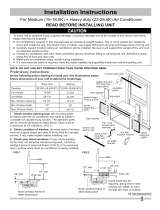
Electrical grounding is required on this appliance.
Recommended grounding method:
For your personal safety, this appliance must be grounded.
This air conditioner includes a power supply cord with a
3-prong grounding plug. To minimize possible electrical shock
hazard:
cord must be plugged into a matching 3-prong grounding type
wall receptacle.
must be grounded in accordance with National Electrical
Code (ANSI/NFPA 70-latest version) and all local codes and
ordinances.
If a matching 3-prong grounding type wall receptacle is not available,
it is the responsibility of the consumer to have a properly grounded
3-prong wall receptacle installed by a qualified electrician.
3-Prong Grounding
Type Wall Rece
3-Prong
Grounding plug
Grounding prong
Power Supply Cord
(6 feet long)
FIG. 1
Preparing for Installation
Installation Tips
For wood-frame casement windows:
It may be necessary to construct a frame, using at least
1" thick wood, with a 15-1/2" wide opening.
For brick or cement building construction:
It may be necessary to put a wood stool strip under air
conditioner, for mounting purposes as shown FIG. 2.
wood strip Bottom Rail of
mounted on air conditioner
top of inner sill /
FIG. 2
Failure to adhere to the following precautions could result in personal injury and product damage.
• Because this unit weighs about 60 to 80 pounds, it is recommended that you have someone help you when
installing your new unit, and that you both use proper lifting techniques. Inspect the condition of the window
where unit will be installed. Be sure it will support the weight of the unit.
This appliance must be installed according to all applicable codes and ordinances.
Handle air conditioner with care. AVOID sharp metal fins on front and rear coils.
Make sure your air conditioner does not fall during installation.
Do not use water collected in the unit for drinking purposes. It is not sanitary.
Tools Required
Flat-head screwdriver • Carpenter's level • Fine tooth saw • Knife and scissors
Phillips-head screwdriver • Tape measure • Electric orhanddrill • Pencil
® DO NOT USE ANY SCREWS OTHER THAN THOSE SPECIFIED IN THESE INSTRUCTIONS.

_Make sureyouhaveallthenecessaryparts•
Installation kit contents (FIG.3):
No. Hardware Qty.
1 Platform 1
2 Support brace 1
3 Adjustment bolt 1
4 Hex flange nut- 1/4 1
5 Track seal 1
6 Side channel seat 1
7 Window sash seal 1
8 Safety bracket 1
9 Screw #10 x 2-1/2" flat-head 2
10 Screw #10 x 1-3/4" flat-head 2
No• Hardware Qty.
11 Screw #10 x 1" pan-head 2
12 Screw #8 x 3/4" pan-head 6
13 Screw #8 x 3/4" self-threading 7
14 Window locking bracket 1
15 Plastic window panel 1
16 Side channel 2
17 Screw-#8 x 3/8"truss head 10 .
18 Panel frame/seal assembly 1
Support bracket 1
19 (For VinyFClad windows)
20 Safety bracket 1
(For VinyFCtad windows)
FIG.3
9or10
or 11or 17
e Use scale below to measure length of your screws• The scale will come in handy
when separating screws for installation•
18
IDENTIFY SCREWS
BY LENGTH ,f ..... 1/2"
318" 3/4"
(10ram) (19ram)
(13mm) (25mm) (44mm) (63mm)
1" 1-3/4" 2-1/2"
1=1/2" 2"
(38mm) (50ram)
_ Choose a sized window, as shown
proper (FIG.4).
* 15-1/2" minimum width
16-1/4" maximum width (for casement windows)
21-1/2" minimum height (with window panel retainer)
* 20-5/16" minimum height (window panel retainer removed)
40" maximum height
16-1/4"
maximum
width
casement
windows)
FIG.4
15-1/2"
minimum
width
21-1/2"
minimum
height
40"
maximum
height
l
q
l
• Height measurement must be of a clear opening above mounting platform•
In some cases, due to a variety of stop and track arrangements, the above
dimensions may vary slightly• If necessary, installation can be made by
alternating window jambs• (See Alternate Window Jamb Applications•)
Choose the proper window location•
Choose a window that allows the cooled air to flow freely and directly into
room(s) you wish to cool. Remember, it is difficult to move air around
corners• Also, choose a window that is within 6 feet of an electrical outlet
as shown (FIG.5). (See Meeting Electrical Requirements/Receptacle wiring
needs•) Do not use an extension cord.
-_FIG.5

Installing Unit in a Sliding Window:
D Attach support brace to platform as shown (FIG.6). Use adjustment
bolt and hex flange nut to complete assembly. Choose slot and adjustment
bolt hole locations that will create a 45 degree angle between platform and
support brace. Try assembly in the window to determine if platform will rest
properly, and allow proper slope (3/16" lower on out side).
• If you are planning to use a siding-protection board (see Step 8) on the
outside of your house, hold board in place when testing assembly in window.
FIG.6
PlatformAssembly
8-11/16" inches FIG.7
E_ Measure, and lightly mark a line 8-11/16" from window jamb:
If any sash stop protrudes more than 1 from the s_dewindow jambs, the
8-11/16" measurement must be increased accordingly (FIG.7). Screen and
storm window frames may also require adjustments to the measurement.
E_ Center platform assembly on the line with inside platform tab
pressed against inside edge of window track as shown (FIG.8A, FIG.8B).
Using the holes in the platform as a guide, mark and drill two 9/64" diameter
holes. Drill holes in either track or stool.
For vinyl-clad windows, you need to install the support bracket on the
window track before you install the platform. Follow the instructions below to
do that.
1. Place the support bracket on the window sill as shown (FIG.8C). Using the
holes in the support bracket as a guide, mark and drill two 1/8" diameter holes.
2. Follow Step 7 to applly the track seal on the room side of window track.
3. After applly the track seal, use two 3/8" screw (item 17) to fixing the support
bracket. Make sure the support bracket is level form side to side.
Proceed to Step 9 after you finish fixing the support bracket.
I_ Peel off protective backing from track seal. Apply seal to room side
of window track (FIG.9). Center of seal strip should coincide with the line
marked in Step 5. The two screw holes drilled in Step 6 should be directly
above seal strip in the inner track.
I_ Securely attach a siding-protection board to side of house (FIG.10).
NOTE: Siding-protection board should be long enough to span 2 wall studs.
?
/
/
FIG.8A
Center platform
assembly on the line
with platform tab pressed
against window track
Alternate screw location
(depending on the inner sill depth)
Platform tab FIG.8B
window track window seal
FIG.8C FIG.9
8-11/16" inches Apply track seal
to window side
Alternate the screw
location (depending on
the height of the sill)
Inside wall
of house
FIG.10
Siding-protection
board

D Place platform assembly, with platform tab against inside of window
track, and attach it to window jamb (FIG.11A). Use appropriate length
screws (Items 9-11 in preparing For Installation).
For Vinyl= Clad windows, place platform assembly, with platform tab
against insidh edge of the support bracket, and use two 3/8" screw (item 17)
to attach it to support bracket as shown (FIG.lIB).
_ Adjust platform assembly so that outside edge is 3/16" lower than
inside edge, as shown (FIG.11). This ensures proper water drainage from
the air conditioner.
li_ Level platform assembly from side=to=side. Also, make sure window
track is level. Use leveling shims as necessary to ensure unit is level from
side-to-side.
li_ Measure height of window opening from top of platform assembly as
shown (FIG.12). Subtract 20-5/8". Mark this measurement on plastic window
panel, along the longer side.
li_ Clamp plastic window panel between a board and a work table, and
cut along cutting line with a fine tooth saw. Remove any burrs with a file.
li_ Fasten side channels to the sides of the air conditioner using 3 screws
(Item 17) per channel as shown (FIG.13). Start with first screw at top of
channel. Make sure hook ends of channels face toward back of unit.
li_ Slide plastic window panel into panel frame as shown (FIG.14), with
the smooth side to the room. Slide panel frame assembly into side channels
of the AC cabinet. Make sure plastic window panel is firmly enclosed on all
sides by the retainer grooves.
Put platform
tab against
inside oftrack
FIG.I1B
FG13•
Fastening
/Side Channels _..___
Plastic _
J window panel ----------
_Cut side channel seal into 2 equal lengths. Remove protective backing
and apply it to the rear side of cabinet side channels, starting just below panel
frame assembly (FIG.15). Pinch off excess length so seal is even with the bottom
of the cabinet side channel.
_To remove front as shown (FIG.16)
1. Remove the two front retaining screws from the front frame.
Outside edge is 3/16"
___wer than inside\
Put platformtab Outside edge is 3/16"
against inside edge lower than inside.\
FIG.12
2. Press firmly on each side of the metal case close to front, approximately 2/3 of the way down.
3. While pressing on the sides of the metal case, gently pull the front out and lift up to release it from the case.
4. Then release the electrical coupler plug.
NOTE: DO NOT push or pull air direction louvers.
_ Place air conditioner in window opening. As shown (FIG.17), it should sit on platform assembly so that
window panel frame and cabinet side channels are against top and side window jambs.
J
FIG.15 FIG.16 FIG.17
Front/ //
Retaining/I L---_
Screw
Apply side
channel seal
to side
just below edge
of panel frame
Slide inner
window sash
firmly against
cabinet.

II!1_ Slide inner window sash firmly against side of the cabinet. Make sure not to peel the seal strips from the window
track and cabinet side channels. If the panel frame does not fit snugly to the inner window sash, secure the panel frame
to the sash with #8 x 3/4" self-threading screws. Use the partially plugged holes in the panel frame. Drill 1/8" pilot
holes for the screws.
_Hook the safety bracket over the base of the unit and fasten it to the front of the platform assembly (FIG.18). Use
a #8-32 x 3/4" self-threading screw.
For Vinyl-Clad windows, use Item 20 (refer to page 3) to fasten the unit to the platform.
NOTE: The bracket prevents movement of the air conditioner (either in or out) after completing the installation.
_Stuff the window sash seal between the vertical sash and the window glass, as shown (FIG.19).
_Use the window locking bracket to lock the inner window sash to the base of the outer window sash (FIG.19).
Use one #8 x 3/4" screw, or #8-32 x 3/4" self-threading screw. (Drill 1/8" pilot hole).
_To replace the front first reconnect the coupler plugs, make the exhaust control positioned through the front in
the proper location. Gently push the front into position on the cabinet. It should click into place. Then replace the
retaining screws that holds the panel in place. DO NOT push or pull the front panel louvers.
Insttall safety bracket
FIG.18 9
window sash seal
safety bracket
(choose the correct
safety bracket
according to your Window
window type) locking
bracket
Alternate Window Jamb Applications
To install in windows having no flanges or wood stops on the top and side jambs, the channels and panel frame must
fit against a matching flange (or 1/16" max. thick angle) attached to the window jambs. FIG.20A shows this angle
installed. FIG.20B & FIG.20C show alternate treatments. On the sash side of the opening, the leading corner of the inner
sash becomes the flange. You can purchase the angle strip locally.
FIG.20A
Add angle to wood stop
FIG.20B
Add wood as shown
FIG.20C
Add 16- or 18- gage angle
Installing the Unit in a Casement Window
Platform Assembly FIG.21
® Open the window the maximum amount to allow for clearance of the cabinet.
The crank handle should be removed to allow the platform to be fastened to
the jamb. If the window cannot open far enough (more than 15-1/2 ) for the
cabinet to clear the window, remove the window entirely by drilling out the
rivets. Bolts can serve as the pivots in the feature.
• To avoid crank handle and window clearance problems, the unit can be
installed in a stationary sash section. However the horizontal mullion and
the 2 glass panels must be removed before installation.
_ Attach support brace to platform as shown (FIG.21). Use the adjustment bolt
and hex flange nut to complete the assembly. Choose the slot and adjustment bolt
hole location that will create a 45 degree angle between the platform and support
brace. Try the assembly in the window to determine if the platform will rest properly,
and allow the proper slope (3/16" lower on outside).
1/4" (6mm) HEX
FLANGE NUT

......._ii!iiiiiiiiiiiiiiiiiiiiiiiiiiiiiiiiiiiiiiiiiiiiiiiiiiiiiiiiiiiiiiiiiiiiiiiiiiiiiiiiiiiiiiiiiiiiiiiiiiiiiiiiiiiiiiiiiiiiiiiiiiiiiiii_!!!ii
® If you are planning to use a siding-protection board (see Step 29) on the outside of your house, hold the board in
place when testing the assembly in the window.
_ Drill a 9/64" diameter pilot hole in the window jamb an equal distance from each side of the jamb (FIG.22),
and 3/16" up from the window sill. If the hole coincides with the window lever slot in the jamb bottom, an additional hole
will have to be drilled through the platform edge and the window jamb to miss this slot.
_Peel off the protective backing from the track seal, and stick the seal to the window sill on the outside of the
bottom jamb as shown (FIG.23).
_ Screw the platform assembly to the window jamb through the pilot hole you drilled in Step 25. Use a #8 x 314"
self-threading screw (FIG.24).
Equal distance from both sides
/_/_/_/64" diameter
_/_FIG.22 pilot hole
Apply track seal to the outside
edge of the bottom window jamb.
Track seal
scr
Window jamb
FIG.24
_ Adjust the platform assembly so that the rear of the air conditioner will be 3/16" lower than the front (tilted about
2° to 4° downward to the outside). After proper installation, condensate should not drain from the overflow drain hole
during normal use, correct the slope otherwise.
• A projection below the base of the air conditioner will require the rear of the platform to be 7/16" lower than the
front to create the 3/16" slant from front to rear (FIG.25).
_ Securely attach a siding-protection board to the side of the house where the platform assembly hit the house
as shown (FIG.26). The siding-protection board should be long enough to span 2 wall studs.
Rear is at least
7/16" lower than
front
FIG.25
Fasten siding
protection board to
the house siding.
FIG.26
_ Measure the height of the window opening from the top of the platform
assembly as shown (FIG.27). Subtract 20-5/8". Mark this measurement on the
plastic window panel, along the longer side.
_ Clamp the plastic window panel between a board and a work table, and
cut along the cutting line with a fine tooth saw. Remove any burrs with a file.
_ Fasten the side channels to the sides of the unit using three screws
(Item 17) per channel. Make sure hook ends of channels face toward the back
of unit.
_ Slide the plastic window panel into the panel frame with the smooth
side to the room. Slide the panel frame assembly into the side channels of
the air conditioner cabinet. Make sure the plastic window panel is firmly
enclosed on all sides by the retainer grooves (FIG.28).
FIG°28
Panel frame
Plastic window panel

_Cut side channel seal into 2 equal lengths. Remove the protective backing and apply it to the rear side of the
cabinet side channels, starting just below the panel frame assembly. Pinch off excess length so the seal is even with
the bottom of the cabinet side channel (FIG.29).
_To remove front as shown (FIG.30)
1. Remove the two front retaining screws from the front frame.
2. Press firmly on each side of the metal case close to the front, approximately 2/3 of the way down.
3. While pressing on the sides of the metal case, gently pull the front out and lift up to release it from the case.
4. Then release the electrical coupler plug.
NOTE: DO NOT push or pull air direction louvers.
_ Place the air conditioner in the window opening as shown (FIG.31). It should sit on the platform assembly
so that the window panel frame and the cabinet side channels are against the top and side window jambs. Side
channels should overlap side window jambs equally.
FiG .29
Apply side
channel
seat to side
channels just
below edge of
panel frame.
FIG.30
i i!! /
FIG.31
_ Drill two 9/64" diameter pilot holes in the top window jamb in line with the partially plugged holes in the panel
frame. Secure the panel frame to the window jamb with two #8-32 x 3/4" self-threading screws. If additional holding is
necessary, two screws may be used on the sides of the panel frame as well.
_ Drill two screw-clearance holes in the cabinet side channels (near bottom) and two 9/64" diameter pilot holes
in the side window jambs. Secure the cabinet side channels to the window jambs with two #8-32 x 3/4" self-threading
screws. When doing this, be careful not to twist the side channel seals with the screws.
NOTE: Inserting screws will prevent the air conditioner from being pushed into the room.
_To replace the front first reconnect the coupler plugs, make the exhaust control positioned through the front
in the proper location. Gently push the front into position on the cabinet. It should click into place. Then replace the
retaining screws that holds the panel in place.
Do not push against or pull upon the front panel louvers.

LEA ESTO ANTES DE MONTAR LA UNIDAD
Para Acondicionadores de Aire en Ventanas de Bisagras y Deslizantes
Para evitar el riesgo de lesiones, de dafios materiales y de dafios al equipo debido a su peso y a los bordes
afilados que puedan quedar expuestos:
Los aparatos de aire acondicionado detallados en este manual suponen un peligro por su excesivo peso. Es
necesaria la intervenci6n de dos o mas personas para mover e instalar el equipo. Para evitar lesiones y
problemas musculares, emplee t6cnicas adecuadas de levantamiento y desplazamiento del mismo.
Inspeccione cuidadosamente la Iocalizaci6n donde piensa instalar el equipo de aire acondicionado. Aseg0rese
de que es capaz de soportar el peso del mismo durante un largo periodo de tiempo.
Manipule el aparato de aire acondicionado con cuidado. Utilice guantes protectores cuando necesite levantarlo
o moverlo. EVlTE tocar las afiladas aletas metalicas que existen en el frontal y en la parte posterior.
Evite que el aparato de aire acondicionado se caiga durante la instalaci6n.
• Estas instrucciones describen la instalaci6n en una ventana de madera tipica con una hoja deslizante
HORIZONTAL, o la instalaci6n en una ventana metalica de BISAGRAS. Puede ser necesaria alguna
modificaci6n cuando se realicen instalaciones en otras ventanas distintas de las aqui mostradas.
Existe un kit de accesorios para ventanas altas que midan hasta 62" (1575 mm). N0mero de parte # EA103W.
Llame al 1-800-4-MY-HOME para pedir el kit.
Cumpliendo los Requisitos Electricos
Peligro de Descargas EI6ctricas y Dafios Personales
• Es necesario conectar a tierra este dispositivo.
• NO LO CONECTE a tierrajunto con una linea de gas.
• NO use una cafieria de agua fria para conectar a tierra si 6sta queda interrumpida en algOn momento por
tramos de plastico, juntas no metalicas o cualquier material aislante.
• Consulte a un electricista cualificado si tiene dudas sobre si el dispositivo queda adecuadamente conectado a tierra.
• NO modifique el enchufe del cable de alimentaci6n. Si no encaja en su tomacorriente, consiga uno
adecuadamente instalado por un electricista cualificado.
• NO coloque un fusible en el circuito de conexi6n neutral o de tierra. Un fusible en esos circuitos puede resultar
en una descarga el6ctrica.
• NO use un cable de extensi6n con este dispositivo.
No seguir estas instrucciones puede provocar descargas el6ctricas, dafios personales serios e incluso la muerte.
RESPETE TODAS LAS NORMATIVAS Y ORDENANZAS LOCALES. NUNCA, BAJO NINGUNA ClRCUNSTACIA,
ELIMINE LA CLAVlJA DE CONEXlON A TIERRA DEL ENCHUFE.
o Si la normativa Io permite, y utiliza un cable de conexi6n a tierra separado, se recomienda que sea un
electricista cualificado quien determine que la via es adecuada para tierra y que no est6 interrumpida por
plasticos, juntas no metalicas u otros materiales aislantes.
2020211A2590

Cableadodeltomacordente:
Elcableadodeltomacorrientedebeseralmenosdelcalibre14.Usesolamentecableadodecobre.Es
responsabilidadsuyadisponerdeuncableadoadecuadoen el tomacorriente, instalado por un electricista cualificado.
Requisitos Electricos:
Una fuente de corriente alterna (AC) de 115 voltios (minimo 103.5, m_ximo 126.5) a 60 Hertzios, con un fusible de
15 amperios en el circuito. Tambi6n se requiere un fusible retardante o un diferencial. DEBE disponer de un circuito
separado que d6 servicio s61oa este dispositivo.
Conexion Electrica: Tomacorriente de 3 clavijas
Se requiere conexi6n a tierra para este dispositivo, con conexi6n a tierra -,
\.
IVletodo recomendado de conexion a tierra:
Para su seguridad personal, este dispositivo debe ser conectado a tierra. Enchufe de 3 clavijas con
Este acondicionador de aire viene provisto de un cable con un enchufe
de 3 clavijas. Para minimizar el posible riesgo de descarga el6ctrica:
el cable debe conectarse a un tomacorriente adecuado.
debe estar conectado a tierra de acuerdo con la Normativa
Nacional Electr6nica (ANSI/NFPA 70-_ltima versi6n) y las
normativas y ordenanzas locales.
Si no dispone de un tomacorriente adecuado de 3 clavijas con
conexi6n a tierra, es responsabilidad del cliente el conseguir que
un electricista cualificado instale uno adecuadamente.
conexi6n a tierra
Clavija de conexi6n a tierra
Cable de Alimentaci6n
(6 pies de largo)
FIG. 1
Preparando la Instalacion
Consejos para la Instalacion
Para ventanas de madera con sistema de bisagras:
Puede ser necesario construir un marco, usando madera de
al menos 1" de grosor, con una apertura de 15-1/2" de ancho.
Para construcciones de ladrillo o cemento:
Puede ser necesario colocar un poyete de madera por debajo
del acondicionador para facilitar el montaje, tal como se
muestra en la FIG. 2.
Rail Inferior del
poyete de madera ubicado en
acondicionador
la parte superior del antepecho /
El no observar las siguientes precauciones puede resultar en dados personales y dados al producto.
• Dado que esta unidad pesa entre 60 y 80 libras, se recomienda que alguien le ayude durante la instalaci6n de
su nueva unidad, y que ambos usen t6cnicas adecuadas de levantamiento de peso. Inspeccione el estado de
la ventana donde instalar_ la unidad. AsegQrese de que ser_ capaz de soportar el peso de la unidad.
Este dispositivo debe instalarse de acuerdo a todas las normativas y ordenanzas aplicables.
Manipule el acondicionador con cuidado. EVITE las aletas afiladas de metal en las rendijas frontal y posterior.
AsegQrese de que su acondicionador no se caiga al suelo durante la instalaci6n.
No use agua recolectada de la unidad como agua potable. No es salubre.
Herramientas Requeridas
Destornilladordecabezaplana • Niveldecarpintero • Sierradedientesfinos • Cuchilloytijeras
DestornilladordecabezaPhillips • Cintam6trica • Taladroelectricoo mecanico • Lapiz
® NO EMPLEE OTROS TORNILLOS DISTINTOS DE LOS ESPECIFICADOS EN ESTAS INSTRUCCIONES.

H AsegOresedequetienetodaslaspiezasnecesarias.
Contenidosdelkitdeinstalaci6n(FIG.3):
NGm. Ferreteria ICant. NGm.
Ferreteria Cant.
FIG.3
yl0
y11y17
1 Plataforma 1
2 Brazodelsoporte 1
3 Pernodeajuste 1
4 Tuercahexagonaldepestafias-1/4 1
5 Burletedelrail 1
6 Burletedelraillateral 1
7 Burletedeespumaparalaventana 1
8 Escuadradeseguridad 1
9 Tornillodecabezaplanadel#I0x2-1/2" 2
10 Tornillodecabezaplanadel#10x2-3/4" 2
11 Tornillodecabezaconicadel#t0 x1"
12 Tornillodecabezaconicadel#8x3/4"
13 Tornilloauto-roscantedel#8x3/4"
14 Escuadradebloqueodelaventana
15 Paneldeplasticoparalaventana
16 Raillateral
17 Tornillodecabezaredondeadadel#8x3/8"
18 Montajedelmarco/burletedelpanel 1
Soportedeapoyo 1
19 (paraventanasconrevestirnientodevinilo)
20 Soportedeseguridad 1
(paraventanasconrevestirnientodevinilo)
• Utilice la escala a continuaci6n para medir la Iongitud de sus tornillos. La
escala es muy pr_ctica cuando ande separando los tornillos para la instalaci6n.
IDENTIFIQUE LOS
TORNILLOS POR 1/2"
(13mm) (25mm) (44mm) (63mm)
1" 1-3/4" 2-1/2"
3/8" 3/4"
(10mm) (19mm)
1-1/2" 2"
(38mm) (50mm)
_ Escoja una ventana de dimensiones apropiadas, como se muestra
(FIG.4).
Anchura minimo de 15-1/2"
:* Anchura maximo de 16-1/4" (para ventanas de bisagras)
Altura minima de 21-1/2" (con ret6n del panel de la ventana)
Altura minima de 20-5/16" (sin el ret6n del panel de la ventana)
Altura m_xima de 40"
Anchura
maxima
16-1/4"
(ventana
de bisagras)
FIG.4
Anchura
minima -
de 15-1/2"
Altura
minima
21-1/2"
Altura
m_xima
40"
• Las medidas de altura deben realizarse sobre el espacio abierto por encima de la
plataforma de montaje. En algunos casos, debido a posibles barreras y disposici6n
de railes, las dimensiones arriba descritas pueden variar ligeramente. Si fuera
necesario, la instalaci6n puede realizarse modificando las jambas de la ventana.
(Yea Montajes Alternativos en las Jambas de las Ventanas.)
Elija una ventana en una posici6n adecuada.
Elija una ventana que permita que el aire frio circule libre y directamente en
la estancia (o estancias) que quiere enfriar. Recuerde, es dificil mover aire
en las esquinas. Del mismo modo, elija una ventana que se encuentre
dentro de un rango de 6 pies de distancia a un tomacorriente, tal como se
muestra (FIG.5). (Vea Cumpliendo los Requisitos EI6ctricos / Cableado del
tomacorriente). No use un cable extensor.
FIG.5

Instalando la Unidad en una Ventana Deslizante:
D Ajuste el brazo de soporte a la plataforma tal como se muestra
(FIG.6). Use un perno de ajuste y una tuerca hexagonal de pestafias para
completar el montaje. Escoja un z6calo y un agujero para el perno que
creen un angulo de 45 grados entre la plataforma y el brazo de soporte.
Pruebe el montaje en la ventana para determinar si la plataforma quedar_
adecuadamente apoyada, y permitir_ una inclinaci6n adecuada (3/16"
m_s bajo en la parte exterior).
• Si piensa usar un tablero antideslizante (ver Paso 8) en el
exterior col6quelo en su sitio durante el testeo del montaje en
la ventana.
_ Mida, y marque ligeramente una linea a 8-11/16"de la jamba de la ventana:
o Si los salientes de la hoja de la ventana se extienden mas de 1"
FIG.6
Montaje de la
®
_'-. TUERCAHEXAGONAL
DEPESTANASDE1/4"
(6mm)
8-11/16" pulgadas FIG.7
desde la jamba, la medida de 8-11/16" deber_ set incrementada
de acuerdo a esa extensi6n (FIG.7). Los marcos de pantallas y
contraventanas tambi6n pueden implicar ajustes en esta medida.
_ Centre el montaje de la plataforma en la linea con la pestafia interior
de la misma presionada contra el borde interior del rail de la ventana tal
como se muestra (FIG.8A, FIG.8B). Usando los agujeros de la plataforma
como guia, marque y taladre dos agujeros de 9/64" de di_metro. Taladre
los agujeros en el rail o en el poyete.
Para ventanas con revestimiento de vinilo, es necesario instalar el soporte
de apoyo en la corredera de la ventana antes de instalar la plataforma. Para
ello, siga las siguientes instrucciones.
1. Coloque el soporte de apoyo en la repisa de la ventana segOn se muestra
(FIG.8C). Usando los agujeros del soporte de apoyo como guia, marque y
perfore dos agujeros con 1/8" de di_metro.
2. Siga el paso 7 para aplicar el sello de la corredera pot el lado de la
habitaci6n.
3. Despu6s de aplicar el sello de la corredera, use dos tornillos de 3/8"
(elemento 17) para fijar el soporte de apoyo. AsegOrese de que el soporte
de apoyo est6 nivelado de un lado a otto.
Avance al paso 9 cuando termine de fijar el soporte de apoyo.
_ Retire el protector de la parle trasera del rail. Aplique el burlete en
la parte del rail que da a la estancia (FIG.9). El centro del burlete debe
coincidir con la linea marcada en el paso 5. Los dos agujeros taladrados en
el paso 6 deben quedar directamente pot encima del burlete del rail interior.
_ Ajuste firmemente el tablero antideslizante en el lado exterior del
muro (FIG.10).
NOTA: El tablero antideslizante debe set Io suficientemente largo como
para albergar 2 tacos de pared.
?
/
/
S>
?
/
FIG.8A
Centre el
montaje de la
plataforma en la linea,
con la pestafia presionando
contra el rail de la ventana
Ubicaci6n altemativa del tornitto
(dependiendo de la profundidad
del antepecho) Pestafia de
la ptataforma FIG.8B
Rail de la Burlete del rail
ventana de la ventana
8-11/16" pulgadas FIG.SC Aptique el burletedel FIG.9 FIG.10
rail en la caradel rail

D Coloqueel montaje de la plataforma, con la pestafia sobre el interior
del rail de la ventana, y aj_stela a la jamba (FIG.11A). Use tornillos de
Iongitud adecuada (items 9-11 en Preparando la Instalaci6n).
Pare ventanas con revestimiento de vinilo, coloque el montaje de la
plataforma con la pestafia de la plataforma contra el borde interior del
soporte de apoyo, y use dos tornillos de 3/8" (elemento 17) para fijarlo al
soporte de apoyo seg5n se muestra (FIG.lIB).
_ Ajuste el montaje de la plataforma de tal forma que extremo exterior
quede 3/16" mas bajo que el extremo interior, tal como se muestra (FIG.11).
Esto asegura el adecuado drenaje del agua del acondicionador.
_ Nivele la plataforma de un lado al otto. Aseg_rese tambi6n de que el
rail de la ventana ester nivelado. Utilice I_minas de nivelado si fuera
necesario para asegurar el nivelado de un lado a otro.
_Mida la altura de la aperture de la ventana desde la parte superior de la
Cotoque la
pestafia de
la plataforma
sobre el interic
del rail.
El extremo exterior queda
3/16" m_sbajo que el interior
FIG.11B
Coloque la
pestar_a de ta
El extremo exterior
plataforma tel como se muestra (FIG.12). Reste 20-5/8". Marque esta medida ptataforma contra queda 3/16" m_s
en el panel de pl_stico de la ventana, en el lado m_s largo, etborde interior bajo que el interior
WSujeteelpaneldeplasticodelaventanaentreunatablayunamesadetrabajo, y l_ff" tl X _/i_-
c6rteloa Iolargoporlalinen marcadaconunasierradedentado%0. Remuevacualquierrebabaconuna
_ Ajuste los railes laterales a los lados del acondicionador usando 3 tornillos
(item 17) por rail tel como se muestra (FIG.13). Empiece por la parte superior del
rail. AsegOrese de que los ganchos del rail quedan hacia la parte trasera de la unidad.
_ Deslice el panel de plastico en el marco tel como se muestra (FIG.14), con el
lado suave hacia la habitaci6n. Deslice el marco del panel en los railes interiores de
la carcase del acondicionador. AsegOrese de que el panel de pl_stico queda firmemente
ajustado a todos los laterales pot los surcos de ret6n.
FIG.13
/
Ajuste de los
/ rafles laterales
_del panel
Panel pl_stico_
FIG.12
/
/
FIG.15 FIG.16
Aplique burlete
al rail lateral
justo pot debajo
del borde del
marco del panel_, deT°rnill°SRet6n/
del Frontal
/
z'
/
FIG.17
Deslice la hoja
interior de la
ventana firmemente
contra la carcase
apoyados contra Ins jambas de la ventana.
de la ventana '
_ Corte el burlete _el rail lateral en 2 piezas de igual Iongitud. Remueva el protector
/
de la parte trasera y apliquelo en la parte trasera de los railes laterales de la carcase,
empezando justo por debajo del marco del panel (FIG.15). Recorte el exceso de burlete
de tel modo que quede alineado con la parte inferior del rail lateral de la carcase.
W Remueva el frontal tel como se muestra (FIG.16)
1. Remueva los dos tornillos de ret6n del marco frontal.
2. Presione firmemente en cada lado de la carcase metatica cerca detfrontal, aproximadamente a 2/3 de distancia hacia abajo.
3. Mientraspresionaen loslateralesde la carcasemetalica,tiresuavementedel frontalhaciafueray levantelopareliberarlode la carcase.
4. Despu6s desconecte el conector el6ctrico.
NOTA: NO tire ni empuje de Ins pales de direccionamiento de aire.
_ Ubique el acondicionador en la aperture de la ventana. Tel como se muestra (FIG.17), debe quedar apoyado
sobre la plataforma de montaje de tel manera que el panel de la ventana y los railes laterales de la carcase queden

I_ Deslice la hoja interior de la ventana firmemente contra el lateral de la carcasa. Aseg0rese de que no remueve
el protector del burlete de los railes de la ventana ni del lateral de la carcasa. Si el marco del panel no se ajusta
c6modamente a la hoja de la ventana, aseg0relo a la misma con tornillos auto-roscantes del #8 x 3/4". Use los agujeros
parcialmente tapados del marco del panel. Taladre agujeros guia de 1/8" para los tornillos.
_ Enganche la escuadra de seguridad sobre la base de la unidad y ajOstela al frontal de la plataforma (FIG.18).
Use un tornillo auto-roscante del #8-32 x 3/4".
Para ventanas con revestimiento de vinilo, use el elemento 20 (consulte la p_gina 3) para ajustar la unidad a la
plataforma.
NOTA: La escuadra evita el movimiento del acondicionador (hacia dentro o fuera) una vez completada la instalaci6n.
_ Rellene con el burlete de espuma para la ventana el espacio vertical entre la hoja y et cristat,tal como se muestra (FIG.19).
_Use la escuadra de bloqueo de la ventana para bloquear la hoja interior a la base de la hoja exterior de la ventana
(FIG.19). Use un tornillo del #8 x 3/4" o un tornillo auto-roscante del #8-32 x 3/4". (Taladre un agujero guia de 1/8").
_Para velvet a colocar el frontal primero reconecte el conector electrico, coloque el control de ventilaci6n posicionado a
traves del frontal en el lugar adecuado. Presione suavemente el frontal en su sitio en la carcasa. Deber_ hacer "clic" al
colocarse. Despu6s recoloque los tornillos de ret6n del panel frontal. NO presione ni tire de las palas del panel frontal.
Instale la escuadra de soporte
FIG.18
FIG.19
escuadra de soporte h_K_r
(seleccione el soporte burlete de espuma
seguridad correcto para la ventana
segOn el tipo de ventana) Escuadra de
bloqueo de la
ventana
Montajes AIternativos en las Jarnbas de las Ventanas
Para instalar el equipo en ventanas que no tengan pesta_as o topes de madera en las jambas, los railes y el marco
del panel deben ajustarse contra una pestaSa adecuada (o en una escuadra de grosor m_ximo de 1/16") que est6
fijada a las jambas. La FIG.20A muestra esta escuadra instalada. Las FIG.20B y FIG.20C muestran otros tratos
alternativos. En el lado de la hoja de la ventana, la esquina de la misma se puede usar como soporte. Puede
conseguir la escuadra en su ferreteria m_s cercana.
FIG.20A FIG.20B
Coloque la escuadra sobre el A_ada un taco de madera
tope de madera como se muestra
Instalando la Unidad en una Ventana de Bisagras
FIG.20C
ASada una escuadra del
calibre 16-6 18-
Plataforma FIG.21
• Abra la ventana Io maximo posible para hacer suficiente sitio a la carcasa.
La manivela deber_ set retirada para permitir que la plataforma sea sujetada
a la jamba. Si la ventana no se puede abrir Io suficiente (m_s de 15-1/2")
para que la carcasa quepa en la ventana, retire la hoja de la ventana
completamente extrayendo los remaches las bisagras. Podr_ usar los
pernos como pivotes durante el proceso.
• Para evitar problemas con el picaporte de la ventana, la unidad puede set
instalada en el marco de una de las hojas de la ventana. En cualquier caso,
los cristales de la ventana y los listones que los separen deben set
removidos antes de la instalaci6n.
_Fije soporte como se (FIG.). perno y hexagonal pestaSas para
el brazo de muestra
21
Use el la tuerca
de
completar el montaje. Escoja un z6calo y un agujero para el perno que creen un _ngulo de 45 grados entre la
plataforma y el brazo de soporte. Pruebe el montaje en la ventana para determinar si la plataforma quedar_
adecuadamente apoyada, y permitir_ una inclinaci6n adecuada (3/16" m_s bajo en la parte exterior).
'_ Tuerca hexagonal de
pesta_as de 1/4" (6mm)

® Siplaneausaruntableroantideslizante(verPaso29)enelexteriordesucasa,sujeteeltableroensusitio
cuandopruebeelmontajeenlaventana.
_ Taladreunagujeroguiade9/64"enlajambadelaventanaaunadistanciaigualdecadaladodelajamba
(FIG.22)y3/16"masarribadelantepechodelaventana.Sielagujerocoincideconlaranuraparaelsegurodela
ventanaenlapartededebajodelajamba,tendr_quetaladrarottoagujeroatrav6sdelbordedelaplataformayla
jambadelaventanaparaasievitardichoagujero.
_ Retireel protector de la parte de arras del burlete del rail y pegue el burlete al antepecho pot fuera de la parte
de debajo de la jamba como se muestra (FIG. 23).
_ Atomille la plataforma a la jamba a trav6s del agujero guia que taladr6 en el paso 25. Utilice un tornillo
auto-roscante del #8 x 3/4" (FIG. 24).
A una distancia igual
de ambos lados
gujero
gula de 9/24"
Ponga el burlete del rail en
el borde exterior de la parte
de abajo de lajamba de la ventana.
Burlete del rail
Jamba de
la ventana
FIG.24
_ Ajuste la plataforma de manera que la parte de atr_s del acondicionador de aire est6 3/16" mas abajo que la
parte de delante (inclinado de 2° a 4° hacia abajo y afuera). Despu6s de hacer la instalaci6n, el condensado no debe
drenar pot el orificio de drenaje durante el uso normal, en caso Io contrario, corrija la inclinaci6n.
o Un saliente en la parte inferior de la base del acondicionador de aire requerir_ que la parte de atr_s de la
plataforma est6 7/16" m_s abajo que la parte frontal para crear la inclinaci6n de 3/16" de delante a atr_s.
_ Ajuste firmemente el tablero antideslizante en el lado exterior del muro donde el
montaje de la plataforma vaya a contactar el muro tal como se muestra (FIG.26). El tablero FIG.27
antideslizante debe set Io suficientemente largo como para albergar 2 tacos de pared.
La parte exterior queda at menos
7/16" m_s bajo que et interior
FIG.25
Ajuste el tabtero
antideslizante en
/el lado exterior
del muro.
FIG.26
_Mida la altura de la apertura de la ventana desde la parte superior de la plataforma
tal como se muestra (FIG.27). Reste 20-5/8". Marque esta medida en el panel de pl_stico
de la ventana, en el lado mas largo.
_ Sujete el panel de plastico de la ventana entre una tabla y una mesa de
FIG.28
trabajo, y c6rtelo a Io largo pot la linea marcada con una sierra de dentado fino.
Remueva cualquier rebaba con una lima.
_ Ajuste los railes laterales a los lados del acondicionador usando 3
tornillos (item 17) pot rail. Aseg0rese de que los ganchos del rail quedan
hacia la parte trasera de la unidad.
_ Deslice el panel de plastico en el marco con el lado suave hacia la habitaci6n.
Deslice el marco del panel en los railes interiores de la carcasa del acondicionador.
Aseg0rese de que el panel de pl_stico queda firmemente ajustado a todos los laterales
pot los surcos de ret6n (FIG.28).
Marco del panel
Panel pt_stico
de la ventana

_ Corte el burlete del rail lateral en 2 piezas de igual Iongitud. Remueva el protector de la parte trasera y apliquelo
en la parte trasera de los railes laterales de la carcasa, empezando justo pot debajo del marco del panel. Recorte el
exceso de burlete de tal modo que quede alineado con la parte inferior del rail lateral de la carcasa (FIG.29).
_ Remueva el frontal tal como se muestra (FIG.30)
1. Remueva los dos tornillos de ret6n del marco frontal.
2. Presione firmemente en cada lado de la carcasa met_lica cerca del frontal, aproximadamente a 2/3 de distancia
hacia abajo.
3. Mientras presiona en los laterales de la carcasa met_lica, tire suavemente del frontal hacia fuera y lev_ntelo para
liberarlo de la carcasa.
4. Despu6s desconecte el conector el6ctrico.
NOTA: NO tire ni empuje de las palas de direccionamiento de aire.
_ Ubique el acondicionador en la apertura de la ventana tal como se muestra (FIG.31). Debe quedar apoyado
sobre la plataforma de montaje de tal manera que el panel de la ventana y los railes laterales de la carcasa queden
apoyados contra las jambas de la ventana. Los railes laterales deben quedar pot encima de las jambas de la ventana
de igual manera en cada lado.
FIG.29
Aplique burlete
al rail lateral
justo por debajo
del borde del
marco del panel.
FIG.30
Tornittos
de ret6n
del frontal
J
FIG.31
_ Taladre dos agujeros guia de 9/64" de diametro en la jamba superior alineado con los agujeros parcialmente
tapados del marco del panel. Asegure el marco a la jamba con dos tornillos auto-roscantes del #8-32 de 3/4". Si fuera
necesario un soporte adicional, pueden usarse otros dos tornillos en los laterales del panel de la misma manera.
_ Taladre dos agujeros para hacer lugar a los tornillos en los laterales de la carcasa (cerca de la parte inferior) y
dos agujeros guia de 9/64" de di_metro en la jamba lateral de la ventana. Asegure los railes laterales de la carcasa a
las jambas con dos tornillos auto-roscantes del #8-32 de 3/4". Cuando haga esto, tenga cuidado de no enrollar el
burlete de los railes laterales con los tornillos.
NOTA: AI insertar los tornillos evitar_ que el acondicionador pueda set extraido hacia la habitaci6n.
Para volver a colocar el frontal primero reconecte el conector el6ctrico, coloque el control de ventilaci6n
posicionado a trav6s del frontal en el lugar adecuado. Presione suavemente el frontal en su sitio en la carcasa.
Deber_ hacer "clic" al colocarse. Despu6s recoloque los tornillos de ret6n del panel frontal.
NO presione ni tire de las palas del panel frontal.

READ BEFORE iNSTALLiNG UNiT
For Slider Casement Air Conditioners
To avoid risk of personal injury, property damage, or product damage due to the weight of this device and sharp
edges that may be exposed:
Air conditioners covered in this manual pose an excessive weight hazard. Two or more people are needed to
move and install the unit. To prevent injury or strain, use proper lifting and carrying techniques when moving unit.
Carefully inspect location where air conditioner will be installed. Be sure it will support the weight of the unit over
an extended period of time.
Handle air conditioner with care. Wear protective gloves whenever lifting or carrying the unit. AVOID the sharp
metal fins of front and rear coils.
Make sure air conditioner does not fall during installation.
• These instructions describe installation in a typical wood framed window with a wood SLIDE-BY sash, or
installation in a metal CASEMENT window. Modification may be necessary when installing in windows made
differently than those shown in these instructions.
A high window accessory kit is available for window heights up to 62" (1575 mm). Part # EA103W.
Call 1-800-4-MY-HOME to order kit.
Meeting Electrical Requirements
Electrical Shock and Personal Injury Hazard
• Electrical ground is required on this appliance.
• DO NOT ground to a gas line.
• If cold water pipe is interrupted by plastic, non-metallic gaskets, or other insulating materials, DO NOT use for
grounding.
• Check with a qualified electrician if you are in doubt as to whether the appliance is properly grounded.
• DO NOT modify power supply cord plug. If it does not fit outlet, have a proper outlet installed by a qualified
electrician.
• DO NOT have a fuse in the neutral or grounding circuit. Afuse in the neutral, or grounding circuit could result in
an electrical shock.
• DO NOT use an extension cord with this appliance.
Failure to follow these instructions could result in electrical shock, serious injury, or death.
OBSERVE ALL LOCAL GOVERNING CODES AND ORDINANCES. DO NOT, UNDER ANY CIRCUMSTANCES,
REMOVE THE POWER SUPPLY CORD GROUNDING PRONG.
o If codes permit, and a separate grounding wire is used, it is recommended that a qualified electrician determine
that the grounding path is adequate and not interrupted by plastic, non-metallic gaskets, or other insulating
materials.
2020211A2590

ReceptacleWiring:
Receptaclewiringshouldbeaminimumof14gauge.Usecopperwireonly.It is your responsibility to provide proper
and adequate receptacle wiring, installed by a qualified electrician.
Electrical Requirements:
A 115 volt (103.5 minimum, 126.5 maximum), 60 Hertz, AC only, 15 ampere fused electrical supply is required. Atime
delay fuse or time delay circuit breaker is also required. A separate circuit, serving this appliance only, MUST be
provided.
Electrical Connection:
Electrical grounding is required on this appliance.
Recommended grounding method:
For your personal safety, this appliance must be grounded.
This air conditioner includes a power supply cord with a
3-prong grounding plug. To minimize possible electrical shock
hazard:
cord must be plugged into a matching 3-prong grounding type
wall receptacle.
must be grounded in accordance with National Electrical
Code (ANSI/NFPA 70-latest version) and all local codes and
ordinances.
If a matching 3-prong grounding type wall receptacle is not available,
it is the responsibility of the consumer to have a properly grounded
3-prong wall receptacle installed by a qualified electrician.
3-Prong Grounding
Type Wall Rece
3-Prong
Grounding plug
Grounding prong
Power Supply Cord
(6 feet long)
FIG. 1
Preparing for Installation
Installation Tips
For wood-frame casement windows:
It may be necessary to construct a frame, using at least
1" thick wood, with a 15-1/2" wide opening.
For brick or cement building construction:
It may be necessary to put a wood stool strip under air
conditioner, for mounting purposes as shown FIG. 2.
wood strip Bottom Rail of
mounted on air conditioner
top of inner sill /
FIG. 2
Failure to adhere to the following precautions could result in personal injury and product damage.
• Because this unit weighs about 60 to 80 pounds, it is recommended that you have someone help you when
installing your new unit, and that you both use proper lifting techniques. Inspect the condition of the window
where unit will be installed. Be sure it will support the weight of the unit.
This appliance must be installed according to all applicable codes and ordinances.
Handle air conditioner with care. AVOID sharp metal fins on front and rear coils.
Make sure your air conditioner does not fall during installation.
Do not use water collected in the unit for drinking purposes. It is not sanitary.
Tools Required
Flat-head screwdriver • Carpenter's level • Fine tooth saw • Knife and scissors
Phillips-head screwdriver • Tape measure • Electric orhanddrill • Pencil
® DO NOT USE ANY SCREWS OTHER THAN THOSE SPECIFIED IN THESE INSTRUCTIONS.

_Make sureyouhaveallthenecessaryparts•
Installation kit contents (FIG.3):
No. Hardware Qty.
1 Platform 1
2 Support brace 1
3 Adjustment bolt 1
4 Hex flange nut- 1/4 1
5 Track seal 1
6 Side channel seat 1
7 Window sash seal 1
8 Safety bracket 1
9 Screw #10 x 2-1/2" flat-head 2
10 Screw #10 x 1-3/4" flat-head 2
No• Hardware Qty.
11 Screw #10 x 1" pan-head 2
12 Screw #8 x 3/4" pan-head 6
13 Screw #8 x 3/4" self-threading 7
14 Window locking bracket 1
15 Plastic window panel 1
16 Side channel 2
17 Screw-#8 x 3/8"truss head 10 .
18 Panel frame/seal assembly 1
Support bracket 1
19 (For VinyFClad windows)
20 Safety bracket 1
(For VinyFCtad windows)
FIG.3
9or10
or 11or 17
e Use scale below to measure length of your screws• The scale will come in handy
when separating screws for installation•
18
IDENTIFY SCREWS
BY LENGTH ,f ..... 1/2"
318" 3/4"
(10ram) (19ram)
(13mm) (25mm) (44mm) (63mm)
1" 1-3/4" 2-1/2"
1=1/2" 2"
(38mm) (50ram)
_ Choose a sized window, as shown
proper (FIG.4).
* 15-1/2" minimum width
16-1/4" maximum width (for casement windows)
21-1/2" minimum height (with window panel retainer)
* 20-5/16" minimum height (window panel retainer removed)
40" maximum height
16-1/4"
maximum
width
casement
windows)
FIG.4
15-1/2"
minimum
width
21-1/2"
minimum
height
40"
maximum
height
l
q
l
• Height measurement must be of a clear opening above mounting platform•
In some cases, due to a variety of stop and track arrangements, the above
dimensions may vary slightly• If necessary, installation can be made by
alternating window jambs• (See Alternate Window Jamb Applications•)
Choose the proper window location•
Choose a window that allows the cooled air to flow freely and directly into
room(s) you wish to cool. Remember, it is difficult to move air around
corners• Also, choose a window that is within 6 feet of an electrical outlet
as shown (FIG.5). (See Meeting Electrical Requirements/Receptacle wiring
needs•) Do not use an extension cord.
-_FIG.5

Installing Unit in a Sliding Window:
D Attach support brace to platform as shown (FIG.6). Use adjustment
bolt and hex flange nut to complete assembly. Choose slot and adjustment
bolt hole locations that will create a 45 degree angle between platform and
support brace. Try assembly in the window to determine if platform will rest
properly, and allow proper slope (3/16" lower on out side).
• If you are planning to use a siding-protection board (see Step 8) on the
outside of your house, hold board in place when testing assembly in window.
FIG.6
PlatformAssembly
8-11/16" inches FIG.7
E_ Measure, and lightly mark a line 8-11/16" from window jamb:
If any sash stop protrudes more than 1 from the s_dewindow jambs, the
8-11/16" measurement must be increased accordingly (FIG.7). Screen and
storm window frames may also require adjustments to the measurement.
E_ Center platform assembly on the line with inside platform tab
pressed against inside edge of window track as shown (FIG.8A, FIG.8B).
Using the holes in the platform as a guide, mark and drill two 9/64" diameter
holes. Drill holes in either track or stool.
For vinyl-clad windows, you need to install the support bracket on the
window track before you install the platform. Follow the instructions below to
do that.
1. Place the support bracket on the window sill as shown (FIG.8C). Using the
holes in the support bracket as a guide, mark and drill two 1/8" diameter holes.
2. Follow Step 7 to applly the track seal on the room side of window track.
3. After applly the track seal, use two 3/8" screw (item 17) to fixing the support
bracket. Make sure the support bracket is level form side to side.
Proceed to Step 9 after you finish fixing the support bracket.
I_ Peel off protective backing from track seal. Apply seal to room side
of window track (FIG.9). Center of seal strip should coincide with the line
marked in Step 5. The two screw holes drilled in Step 6 should be directly
above seal strip in the inner track.
I_ Securely attach a siding-protection board to side of house (FIG.10).
NOTE: Siding-protection board should be long enough to span 2 wall studs.
?
/
/
FIG.8A
Center platform
assembly on the line
with platform tab pressed
against window track
Alternate screw location
(depending on the inner sill depth)
Platform tab FIG.8B
window track window seal
FIG.8C FIG.9
8-11/16" inches Apply track seal
to window side
Alternate the screw
location (depending on
the height of the sill)
Inside wall
of house
FIG.10
Siding-protection
board
/