Shimano BT-DN110 Dealer's Manual
- Category
- Bicycles
- Type
- Dealer's Manual

(English)
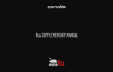
DM-RX815-00
Dealer’s Manual
ROAD MTB Trekking
City Touring/
Comfort Bike
URBAN SPORT E-BIKE
RX815 series
SHIMANO GRX
ST-RX815
FD-RX815
RD-RX815
RD-RX817
SHIMANO
SW-R9150
SM-EW90-A
SM-EW90-B
EW-RS910
EW-WU111
EW-SD50
EW-SD50-I
EW-JC130
SM-EWC2
SM-JC40
SM-JC41
SM-BTR1
BT-DN110
BT-DN110-A
BM-DN100
SM-BA01
SM-BCR1
SM-BCR2
SM-BCC1

2
CONTENTS
CONTENTS .................................................................................2
IMPORTANT NOTICE ..................................................................6
TO ENSURE SAFETY ...................................................................7
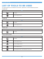
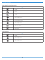
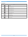
LIST OF TOOLS TO BE USED ....................................................26
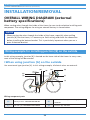
INSTALLATION/REMOVAL .......................................................29
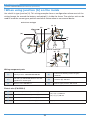
OVERALL WIRING DIAGRAM (external battery specifications) .........29
• Wiring example for installing junction [B] on the outside .................................................. 29
• Wiring example for installing junction [B] on the inside ..................................................... 32
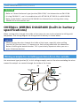
OVERALL WIRING DIAGRAM (built-in battery specifications) ..........34
• Wiring example for installing junction [A] on the outside .................................................. 34
• Wiring example for installing junction [A] on the inside .................................................... 35
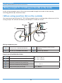
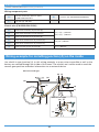
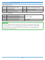
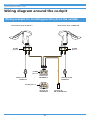
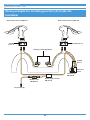
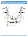
Wiring diagram around the cockpit ....................................................37
• Wiring example for installing junction [A] on the outside .................................................. 37
• Wiring example for installing junction [A] inside the handlebar........................................ 38
• Wiring example for installing junction [A] inside the frame ............................................... 39
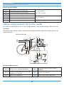
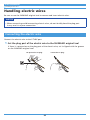
Handling electric wires ........................................................................40
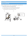
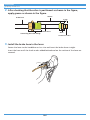
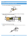
• Connecting the electric wire .................................................................................................. 40
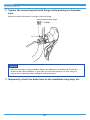
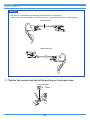
• Disconnecting the electric wire ............................................................................................. 41
• Insertion direction of the electric wires for built-in use ...................................................... 42
• Finishing for external wiring ................................................................................................. 42
• Finishing for internal wiring .................................................................................................. 44
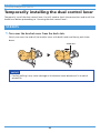
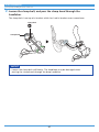
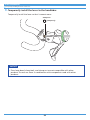
Temporarily installing the dual control lever ..................................... 46
• ST-RX815.................................................................................................................................. 46
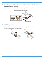
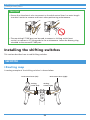
Installing the shifting switches ...........................................................50
• SW-R9150 ................................................................................................................................ 50
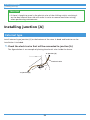
Installing junction [A] ..........................................................................54
• External type ........................................................................................................................... 54
• Built-in bar end type .............................................................................................................. 57
• Built-in frame type ................................................................................................................. 62
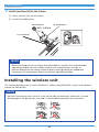
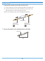
Installing the wireless unit ..................................................................63

3
Temporarily installing the front derailleur ......................................... 65
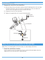
• When there is a mounting boss on the seat tube ................................................................ 65
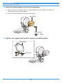
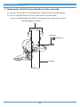
• When there is no mounting boss on the seat tube .............................................................. 66
• Connecting the electric wire .................................................................................................. 69
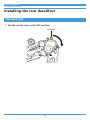
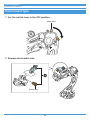
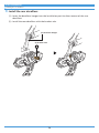
Installing the rear derailleur ................................................................71
• Standard type ......................................................................................................................... 71
• Direct mount type .................................................................................................................. 73
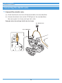
• Connecting the electric wire .................................................................................................. 75
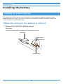
Installing the battery ...........................................................................76
• Installing the external battery ............................................................................................... 76
• Installing the built-in battery ................................................................................................ 84
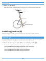
Installing junction [B] ...........................................................................87
• External type ........................................................................................................................... 87
• Built-in type ............................................................................................................................ 90
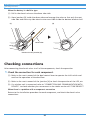
Checking connections ..........................................................................93
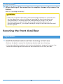
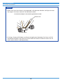
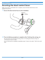
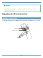
Securing the front derailleur ...............................................................94
• Preparations ............................................................................................................................ 94
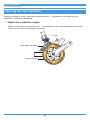
• Securing the front derailleur ................................................................................................. 96
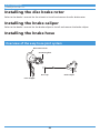
Installing the disc brake rotor .............................................................99
Installing the brake caliper ..................................................................99
Installing the brake hose .....................................................................99
• Overview of the easy hose joint system ................................................................................ 99
• Checking the length of the hose ......................................................................................... 100
• Cutting the hose ................................................................................................................... 101
• Connecting the hose ............................................................................................................ 107
Securing the dual control lever .........................................................112
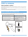
HOW TO OPERATE .................................................................113
Gear position control .........................................................................113
• Points to remember when shifting the front ..................................................................... 113
• Points to remember during rear gear shifting ................................................................... 114
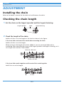
ADJUSTMENT ........................................................................115
Installing the chain .............................................................................115

4
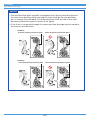
Checking the chain length .................................................................115
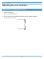
Adjusting the rear derailleur .............................................................117
• Adjusting the end adjustment screw .................................................................................. 117
• Gear shifting adjustment in adjustment mode .................................................................. 119
• Adjusting the stopper bolt .................................................................................................. 121
Adjusting the front derailleur ...........................................................123
• Checking bolt positions ........................................................................................................ 123
• Adjusting the top side .......................................................................................................... 124
• Adjusting the lowest position in adjustment mode ........................................................... 125
• Adjusting the top position in adjustment mode ................................................................ 127
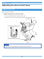
Adjusting the dual control lever .......................................................130
• Adjusting the reach .............................................................................................................. 130
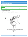
• Adjusting the free stroke ..................................................................................................... 131
Charging the battery ...........................................................133
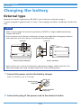
External type ......................................................................................133
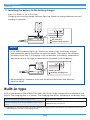
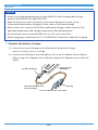
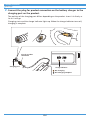
Built-in type ........................................................................................ 134
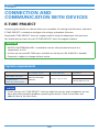
CONNECTION AND COMMUNICATION WITH DEVICES .........138
E-TUBE PROJECT .................................................................................138
• System requirements ............................................................................................................ 138
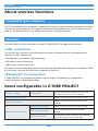
About wireless functions ...................................................................139
• Compatible cycle computers ................................................................................................ 139
• Functions ............................................................................................................................... 139
Items configurable in E-TUBE PROJECT ............................................139
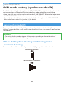
Shift mode setting (synchronized shift) ...........................................140
• Semi-synchronized shift ....................................................................................................... 140
• Synchronized shift ................................................................................................................ 142
MAINTENANCE ......................................................................143
Replacing the brake pads ..................................................................143
SHIMANO genuine mineral oil replacement ....................................143
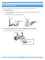
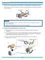
• Draining the mineral oil ....................................................................................................... 143
• Adding mineral oil and bleeding air ................................................................................... 148

5
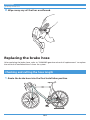
Replacing the brake hose ..................................................................164
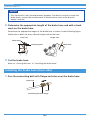
• Checking and cutting the hose length ................................................................................ 164
• Installing the brake hose (lever side) .................................................................................. 165
• Installing the brake hose (caliper side) ............................................................................... 168
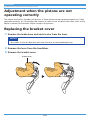
Adjustment when the pistons are not operating correctly ............170
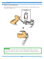
Replacing the bracket cover ..............................................................170
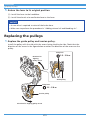
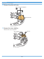
Replacing the pulleys .........................................................................172
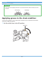
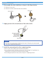
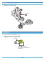
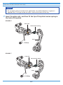
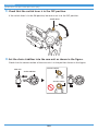
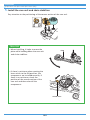
Applying grease to the chain stabilizer ............................................173
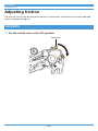
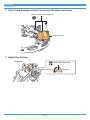
Adjusting friction ...............................................................................176
• RD-RX815 .............................................................................................................................. 176
• RD-RX817 .............................................................................................................................. 180
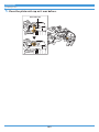
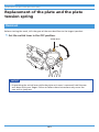
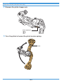
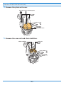
Replacement of the plate and the plate tension spring .................183
• Removal ................................................................................................................................ 183
• Installation ............................................................................................................................ 186

6
IMPORTANT NOTICE
IMPORTANT NOTICE
• This dealer's manual is intended primarily for use by professional bicycle mechanics.
Users who are not professionally trained for bicycle assembly should not attempt to
install the components themselves using the dealer's manuals.
If any part of the information on the manual is unclear to you, do not proceed with the
installation. Instead, contact your place of purchase or a bicycle dealer for their
assistance.
• Make sure to read all owner's manuals included with products.
• Do not disassemble or modify the product other than as stated in the information
contained in this dealer's manual.
• All owner's manuals and dealer's manuals can be viewed on-line on our website (http://
si.shimano.com).
• For consumers who do not have easy access to the internet, please contact a SHIMANO
distributor or any of the SHIMANO offices to obtain a hardcopy of the user's manual.
• Please observe the appropriate rules and regulations of the country, state or region in
which you conduct your business as a dealer.
• The Bluetooth
®
wordmark and logo are registered trademarks owned by Bluetooth SIG,
Inc., and are used under a licensing agreement by SHIMANO INC.
Other trademarks and trade names belong to their respective owners.
For safety, be sure to read this dealer's manual thoroughly before use, and
follow it for correct use.
The following instructions must be observed at all times in order to prevent personal injury
and physical damage to equipment and surroundings.
The instructions are classified according to the degree of danger or damage which may occur
if the product is used incorrectly.
DANGER
Failure to follow the instructions will result in death or serious
injury.
WARNING
Failure to follow the instructions could result in death or
serious injury.
CAUTION
Failure to follow the instructions could cause personal injury or
physical damage to equipment and surroundings.

7
TO ENSURE SAFETY
TO ENSURE SAFETY
DANGER
Be sure to also inform users of the following:
Lithium-ion battery
Be sure to observe the following instructions in order to avoid burns or other injury from
fluid leakage, overheating, fire, or explosion.
• Use the designated battery charger to charge the battery. If any non-specified items are
used, fire, overheating or leakage may occur.
• Do not heat the battery or throw it into fire. If this is not observed, fire or bursting may
occur.
• Do not deform, modify, disassemble or apply solder directly to the battery. Do not use or
leave the battery in places which may exceed 60°C in temperature, such as places which
are exposed to direct sunlight, inside vehicles on hot days or near stoves. If this is not
observed, leakages, overheating or bursting may cause fire, burns, or other injuries.
• Do not connect the (+) and (-) terminals with metallic objects. Do not carry or store the
battery together with metallic objects such as necklaces or hairpins. If this is not
observed, short-circuits, overheating, burns or other injury may occur.
• If any liquid leaking from the battery gets into the eyes, immediately wash the affected
area with clean water without rubbing the eyes, and then seek medical attention.
Battery charger/Battery charger cord
Be sure to observe the following instructions in order to avoid burns or other injury from
fluid leakage, overheating, fire, or explosion.
• Do not get the battery charger wet or use it while it is wet, and do not touch or hold it
with wet hands. If this is not observed, problems with operation or electric shocks may
occur.
• Do not use the battery charger when it is covered with a cloth or other material. If this is
not observed, heat may build up and the case may become deformed, or fire, ignition, or
overheating may occur.
• Do not disassemble or modify the battery charger. If this is not observed, electric shocks
or injury may occur.
• Use the battery charger at the specified power supply voltage only. If a power supply
voltage other than that specified is used, fire, destruction, smoke, overheating, electric
shocks or burns may occur.

8
TO ENSURE SAFETY
• Do not touch the metallic parts of the device or the power plug on the AC adapter or
other parts if there is a lightning storm. If lightning strikes, electric shocks may occur.
SM-BCR2: Battery charger for SM-BTR2/BT-DN110/BT-DN110-A
• Use an AC adapter with a USB port that has a voltage of 5.0Vdc and a current equal to or
higher than 1.0Adc. If the one with a current lower than 1.0 A is used, the AC adapter
may heat up, potentially causing a fire, smoke, overheating, destruction, electric shock,
or burns.
WARNING
• Be sure to follow the instructions provided in the owner's manuals when installing the
product.
It is recommended to use SHIMANO genuine parts only. If parts such as bolts and nuts
become loose or damaged, or if adjustments are not carried out correctly, the bicycle may
suddenly fall over, which may cause serious injury.
•
Be sure to wear safety glasses or goggles to protect your eyes while performing
maintenance tasks such as replacing parts.
• This dealer's manual is for use with the SHIMANO GRX RX815 series (electronic gear
shifting system) only.
For information on products not explained in this manual, search for the model on our
website (http://si.shimano.com).
• After reading the dealer's manual thoroughly, keep it in a safe place for later reference.
Be sure to also inform users of the following:
• Intervals between maintenance depend on the use and riding circumstances. Clean the
chain with an appropriate chain cleaner regularly. Never use alkali based or acid based
solvents such as rust cleaners. If those solvents are used the chain might break and
cause serious injury.
• Check that the wheels are fastened securely before riding the bicycle. If the wheels are
loose in any way, they may come off the bicycle and cause serious injury.
• Check the chain for any damage (deformation or crack), skipping, or other abnormalities
such as unintended gear shifting. If any problems are found, consult your place of
purchase or a distributor.
• The chain may break, and you may fall.
• Be careful not to let the hemming of your clothes get caught in the chain while riding.
Otherwise, you may fall off the bicycle.

9
TO ENSURE SAFETY
About the multi-shifting function
• Connecting this system to E-TUBE PROJECT and switching [Multi shift mode setting] to
[ON] will allow you to continuously shift gears while the shifting switch is held down.
When modifying this setting, carefully read "Items configurable in E-TUBE PROJECT" in
this dealer's manual.
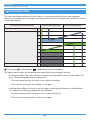
Gear-shifting interval
• [Gear-shifting interval] can be set to one of five levels as a multi-shifting function setting
in E-TUBE PROJECT: [Very Fast], [Fast], [Normal], [Slow], or [Very Slow] (Default: [Normal]).
• A faster [Gear-shifting interval] setting will result in faster gear shifting. The rider can
quickly adjust the traveling speed and the speed at which the front chainwheel turns
("cadence" below) in response to changes in riding conditions.
However, if a gear shifting operation is performed at an insufficient cadence when the
system is set to a fast gear-shifting interval, the chain may be unable to follow the
movement of the rear derailleur, resulting in the following problems.
– The chain may slip over the tip of the cassette sprocket teeth
– The cassette sprocket may deform
– The chain may break
• Fully understand the features of the gear-shifting interval, and then set the gear-shifting
interval according to the riding conditions, such as the terrain and the riding style of the
rider.
Gear-shifting
interval
Benefits Drawbacks
Fast setting
• Quick multi-shifting is possible
• The rider can quickly adjust the
cadence or traveling speed in
response to changes in the riding
conditions
• A high cadence is required when
gear shifting
• Unintended over-shifting occurs
easily
Slow setting
• Gear shifting can be performed
reliably
• Gear shifting takes some time
Lithium-ion battery
• Do not place the battery into fresh water or sea water, and do not allow the battery
terminals to get wet. If this is not observed, fire, bursting, ignition, or overheating may
occur.
• Do not use the battery if it has any noticeable scratches or other external damage. If this
is not observed, bursting, overheating or problems with operation may occur.

10
TO ENSURE SAFETY
• Do not throw or subject the battery to strong shock. If this is not observed, bursting,
overheating or problems with operation may occur.
• Do not use the battery if leakages, discoloration, deformation or any other abnormalities
occur. If this is not observed, bursting, overheating or problems with operation may
occur.
• If any battery fluid gets on your skin or clothes, wash it off immediately with clean water.
The leaked fluid may damage your skin.
• The operating temperature ranges for the battery are given below. Do not use the
battery in temperatures outside these ranges. If it is used or stored in temperatures
which are outside these ranges, fire, injury or problems with operation may occur.
1. During discharge: -10°C - 50°C
2. During charging: 0°C - 45°C
SM-BTR1: Lithium-ion battery (external type)
• If the battery does not become fully charged within the charging time, stop charging. If
this is not observed, fire, bursting, ignition, or overheating may occur.
SM-BTR2/BT-DN110/BT-DN110-A: Lithium-ion battery (built-in type)
• If the battery does not become fully charged after 4 hours, stop charging. If this is not
observed, fire, bursting, ignition, or overheating may occur.
Battery charger/Battery charger cord
SM-BCR1: Battery charger for SM-BTR1
• Hold the power plug when connecting or disconnecting from the electrical outlet. Failure
to do so may cause a fire or electric shock.
• If the following occurs, stop using the device and contact your place of purchase. A fire
or electric shock may occur.
* If heat or acrid-smelling smoke is coming out from the power plug.
* There is a bad connection inside the power plug.
• Do not overload the electrical outlet with appliances beyond its rated capacity, and use
only a 100 - 240 V AC electrical outlet. If the electrical outlet is overloaded by connecting
too many appliances using adapters, overheating resulting in fire may occur.
• Do not damage the power cord or power plug. (Do not damage, modify, let near hot
objects, bend, twist or pull them; do not place heavy objects on top or bundle them
tightly.) If they are used while damaged, fire, electric shocks or short-circuits may occur.
• Do not use the battery charger with commercially-available electrical transformers
designed for overseas use (travel converters), as they may damage the battery charger.
• Always be sure to insert the power plug as far as it will go. If this is not observed, fire
may occur.

11
TO ENSURE SAFETY
SM-BCR2: Battery charger for SM-BTR2/BT-DN110/BT-DN110-A
• Do not use any USB cable other than the USB cable which is supplied with the PC linkage
device. This may cause a charging error, fire, or failure to connect to PC due to
overheating.
• Do not connect the battery charger to PC when it is on standby. This may cause a PC
failure depending on its specifications.
• When connecting or disconnecting the USB cable or the charging cable, be sure to hold
the cable by the plug. Failure to do so may cause a fire or electric shock.
If the following occurs, stop using the device and contact your place of purchase. A fire
or electric shock may occur.
* If heat or acrid-smelling smoke is coming out from the power plug.
* There is a bad connection inside the power plug.
• If it thunders while charging with an AC adapter with a USB port, do not touch the
device, bicycle, or the AC adapter. If lightning strikes, electric shocks may occur.
• Use an AC adapter with a USB port that has a voltage of 5.0Vdc and a current equal to or
higher than 1.0Adc. If the one with a current lower than 1.0Adc is used, a charging error
may occur or the AC adapter may heat up, leading to a fire.
• Do not use a USB hub when connecting the cable to a computer USB port. This may cause
a charging error or fire due to overheating.
• Be careful not to damage the charging cable. (Do not damage, modify, let near hot
objects, bend, twist or pull them; do not place heavy objects on top or bundle them
tightly.) If they are used while damaged, fire, electric shocks or short-circuits may occur.
Brake
• Each bicycle may handle slightly differently depending on the model. Therefore, be sure
to learn the proper braking technique (including brake lever pressure and bicycle control
characteristics) and operation of your bicycle. Improper use of your bicycle's brake system
may result in a loss of control or a fall, which could lead to severe injury. For proper
operation, consult a professional bicycle dealer or the bicycle's owner's manual. It is also
important to practice riding and braking, etc.
• If the front brake is applied too strongly, the front wheel may lock and the bicycle may
fall forward, and serious injury may result.
• Always make sure that the front and rear brakes are working correctly before riding the
bicycle.
• The required braking distance will be longer during wet weather. Reduce your speed and
apply the brakes early and gently.

12
TO ENSURE SAFETY
• If the road surface is wet, the tires will skid more easily. If the tires skid, you may fall off
the bicycle; therefore, to avoid this, reduce your speed and apply the brakes early and
gently.
Hydraulic disc brake
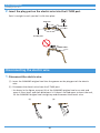
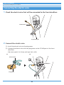
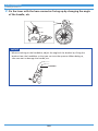
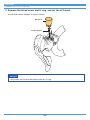
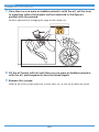
• Please make sure to keep your fingers away from the
rotating disc brake rotor. The disc brake rotor is sharp
enough to inflict severe injury to your fingers if caught in
the openings of the disc brake rotor while it is moving.
• The calipers and disc brake rotor will become hot when the brakes are operated; do not
touch them while riding or immediately after dismounting from the bicycle. Otherwise,
you may get burned.
• Be careful not to allow any oil or grease to get onto the disc brake rotor and brake pads.
Otherwise, the brakes may not work correctly.
• If any oil or grease does get on the brake pads, you should consult a place of purchase or
a distributor. Otherwise, the brakes may not work correctly.
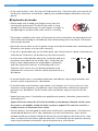
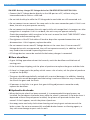
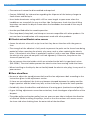
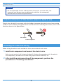
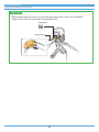
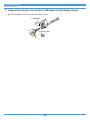
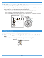
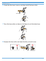
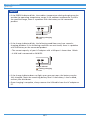
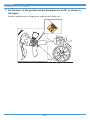
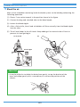
• If noise occurs during brake operation, the brake pads may
have been worn down to the usable limit. Check that the
brake system temperature has cooled down sufficiently,
and then check the thickness of the brake pad. If the
thickness is 0.5 mm or less, the brake pad needs to be
replaced with a new one. Consult a place of purchase or a
distributor.
0.5 mm2 mm
• If the disc brake rotor is cracked or deformed, immediately stop using the brakes and
consult a place of purchase or a distributor.
• If the disc brake rotor becomes worn down to a thickness of 1.5 mm or less, or if the
aluminum surface appears, immediately stop using the brakes and consult a place of
purchase or a distributor. The disc brake rotor may break, and you may fall off the
bicycle.
• Vapor lock may occur if the brakes are applied continuously; therefore, please refrain
from doing this.
Vapor lock occurs when the oil inside the brake system becomes heated, which causes
the water or air bubbles inside the brake system to expand. This can then result in a
sudden increase in the brake lever stroke.
• The disc brake is not designed to work when the bicycle is upside down. If the bicycle is
turned upside down or on its side, the brake may not work correctly, and a serious
accident could occur. Before riding the bicycle, be sure to depress the brake lever a few
times to check that the brakes operate normally. If the brakes do not operate normally,
stop using the brakes and consult a place of purchase or a distributor.

13
TO ENSURE SAFETY
• If you feel no resistance when depressing the brake lever, immediately stop using the
brakes and consult a place of purchase or a distributor.
• If fluid leaks occur, immediately stop using the brakes and consult a place of purchase or
a distributor.
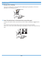
For installation to the bicycle, and maintenance:
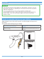
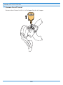
• When the shifting switch is operated, the powerful motor which drives the front
derailleur will operate to the shifting position without stopping, so be careful not to get
your fingers caught.
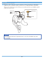
Hydraulic disc brake
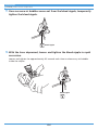
• Please make sure to keep your fingers away from the
rotating disc brake rotor during installation or
maintenance of the wheel. The disc brake rotor is sharp
enough to inflict severe injury to your fingers if caught in
the openings of the disc brake rotor while it is moving.
• If the disc brake rotor is cracked or warped, be sure to replace the disc brake rotor with a
new one.
• If the disc brake rotor becomes worn down to a thickness of 1.5 mm or if the aluminum
surface becomes visible on one side, be sure to replace the disc brake rotor with a new
one.
• Check that the brake system has cooled down sufficiently before attempting brake
system maintenance.
• Use only SHIMANO genuine mineral oil. If other types of oil are used, it may cause
problems with brake operation, and cause vapor lock or the brake system to be unusable
• Be sure to use only oil from a freshly-opened container, and do not re-use oil which has
been drained from the bleed nipple. Old or reused oil may contain water, which could
cause vapor lock in the brake system.
• Be careful not to let water or air bubbles get into the brake system. Otherwise, vapor
lock may occur. Be particularly careful when removing the cover of the reservoir tank.
• If cutting the hose in order to adjust the length of the brake hose, or when changing
over the brake hose from left to right or vice versa, be sure to bleed the air from the
hose according to the steps in "Adding mineral oil and bleeding air".

14
TO ENSURE SAFETY
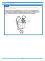
• When turning the bicycle upside down or on its side, the brake system may have some air
bubbles inside the reservoir tank which are still there when the bleed screw is closed, or
which accumulate in various parts of the brake system when it is used for long periods.
This disc brake system is not designed to work with the bicycle upside down. If the bicycle
is turned upside down or on its side, any air bubbles inside the reservoir tank may move
in the direction of the calipers and if the bicycle is ridden in this condition, there is a
danger that the brakes may not operate and a serious accident could occur. If the bicycle
has been turned upside down or on its side, be sure to operate the brake lever a few
times to check that the brakes operate normally before riding the bicycle, and if the
brakes do not operate normally, adjust them according to the following procedure.
If brake does not seem to work (feels sluggish) when the brake lever is depressed
Set the bleed section of the brake lever so that it is parallel to the ground, and then
gently depress the brake lever several times and wait for the air bubbles to return to the
reservoir tank.
If the brakes lever still feels sluggish, bleed the air (refer to "Adding mineral oil and
bleeding air").
• If the quick release lever on the hub is on the same side as the disc brake rotor, they may
interfere with each other, which is dangerous, so check that they do not.
• SHIMANO disc brake systems are not compatible with tandem bicycles. Because tandem
bicycles are heavier, the stress on the brake system increases during brake operation. If
hydraulic disc brakes are used with tandem bicycles, the oil temperature will become too
high and vapor locks or ruptures in the brake hoses may occur, causing the brakes to fail.
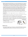
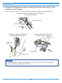
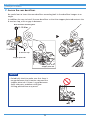
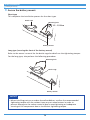
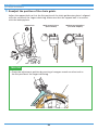
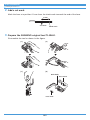
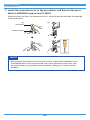
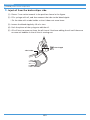
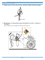
• When installing the brake caliper using bolt
fixing pins, be sure to use mounting bolts of
the appropriate length.
If not, the bolt fixing pins may not be securely
fastened, and the bolts may fall out.
Bolt fixing pin
Brake hose
• After installing the brake hose to the brake unit, adding SHIMANO genuine mineral oil
and bleeding air bubbles, depress the brake lever several times to check that the brakes
are operating normally and there are no fluid leaks from the hose or the system.

15
TO ENSURE SAFETY
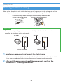
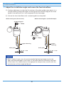
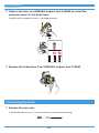
• The connector insert is for this brake hose only. Use an appropriate connector insert
according to the following table. Use of a connector insert incompatible with the brake
hose may cause fluid leaks.
Model number Length Color
SM-BH90-JK-SSR 11.2 mm Silver
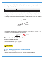
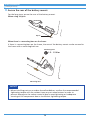
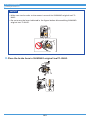
• Do not reuse the olive or the connector insert when reinstalling. A damaged or reused
olive, or connector insert, may not provide a secure brake hose connection, possibly
causing the brake hose to disconnect from the calipers or brake lever.
If the brake hose becomes disconnected, there is a danger that the brakes may suddenly
stop working.
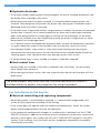
Cut end
Connecting bolt
Brake hose
Olive
Connector
insert
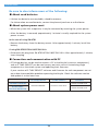
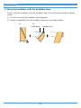
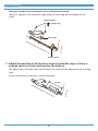
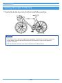
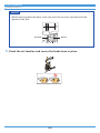
• Cut the brake hose so that the cut end is perpendicular to the length of the hose. If the
brake hose is cut at an angle, fluid leaks may result.
90°
Points to note about the handlebars
EW-RS910 (Built-in bar end type)
• Handle inner diameter: ø20.5 - 21.5 mm
• Handle outer diameter: ø23.8 - 24.2 mm
CAUTION
Be sure to also inform users of the following:
Lithium-ion battery
• Store the battery in a safe place away from the reach of infants and pets.

16
TO ENSURE SAFETY
SM-BTR1: Lithium-ion battery (external type)
• When you do not use the battery for a long period, remove and charge the battery
before storage.
SM-BTR2/BT-DN110/BT-DN110-A: Lithium-ion battery (built-in type)
• When you do not use the battery for a long period, charge the battery before storage.
Battery charger/Battery charger cord
SM-BCR1: Battery charger for SM-BTR1
• Disconnect the power plug from the electrical outlet before cleaning the battery charger.
SM-BCR2: Battery charger for SM-BTR2/BT-DN110/BT-DN110-A
• Disconnect the USB cable or the charging cable when performing maintenance.
Hydraulic disc brake
Cautions on SHIMANO genuine mineral oil
• Contact with eyes may result in irritation. In the event of contact with eye, wash with
water and seek medical attention immediately.
• Contact with skin may cause a rash and discomfort. In the event of contact with skin,
wash well with soap and water.
• Inhalation of SHIMANO genuine mineral oil mist or vapors may cause nausea. Cover your
nose and mouth with a respirator type mask and use in a well-ventilated area. If
SHIMANO genuine mineral oil vapor is inhaled, go immediately to an area with fresh air
and cover up with a blanket. Stay warm and calm, and seek professional medical advice.
Burn-in period
• Disc brakes have a burn-in period, and the braking force will gradually increase as the
burn-in period progresses. Make sure that you are aware of any such increases in braking
force when using the brakes during the burn-in period.
For installation to the bicycle, and maintenance:
Hydraulic disc brake
Handling SHIMANO genuine mineral oil
• Contact with eyes may result in irritation. Use safety glasses when handling, and avoid
contact with eyes.
In the event of contact with eye, wash with water and seek medical attention
immediately.
• Contact with skin may cause a rash and discomfort. Use gloves when handling.
In the event of contact with skin, wash well with soap and water.

17
TO ENSURE SAFETY
• Do not drink. May cause vomiting or diarrhea.
• Keep out of reach of children.
• Do not cut, let near heat, weld or pressurize the mineral oil container, as this may cause
explosion or fire.
• Disposal of Used Oil: Follow local county and/or state codes for disposal.
• Storage method: Keep the container sealed to prevent foreign objects and moisture from
getting inside, and store it in a cool, dark area away from direct sunlight or heat.
Keep from heat or flame, Petroleum Class III, Danger level III
Brake hose
• When cutting the brake hose, handle the knife carefully so as not to cause injury.
• Be careful to avoid injury from the olive.
NOTICE
Be sure to also inform users of the following:
• Be sure to rotate the crank while performing all switch operations related to gear
shifting.
• This is a small waterproof connector, so do not repeatedly connect and disconnect the
electric wire too often. It may impair the function.
• Be careful not to let water get into the E-TUBE port area.
• The components are designed to be fully waterproofed to withstand wet weather riding
conditions; however, do not deliberately place them into water.
• Do not clean the bicycle with a high-pressure washer. If water gets into any of the
components, operating problems or rusting may result.
• Be sure to keep turning the crank during gear shifting operations.
• Handle the product carefully, and avoid subjecting it to any strong shocks.
• Do not use thinners or similar substances to clean the products. Such substances may
damage the surfaces.
• If gear shifting operations do not feel smooth, wash the derailleur and lubricate all
moving parts.

18
TO ENSURE SAFETY
• Keep away from magnetic objects. If this is not observed, problems with operation may
occur.
If the product includes a magnet, make sure to use the included magnet to install it in
the specified location.
• Contact the place of purchase for updates of the component software. The most up-to-
date information is available on the SHIMANO website.
• Products are not guaranteed against natural wear and deterioration from normal use
and aging.
• For maximum performance we highly recommend SHIMANO lubricants and maintenance
products.
Lithium-ion battery
• Lithium-ion batteries are recyclable, valuable resources.
For information on used batteries, contact the place of purchase or a distributor.
• Charging can be carried out at any time regardless of the amount of charge remaining.
Always be sure to use the special battery charger to charge the battery until it is fully
recharged.
• The battery is not fully charged at the time of purchase. Before riding, be sure to fully
charge the battery.
• If the battery has become completely empty, charge it as soon as possible. If you leave
the battery without charging it, it will cause the battery to deteriorate.
• The battery is an exhaustible item. The battery will gradually lose its capacity to charge
after repeated use. If the length of time that the battery can be used becomes extremely
short, it has probably reached the end of its life, and so you will need to purchase a new
battery.
• The life of the battery will vary depending on factors such as the storage method, the
usage conditions, the surrounding environment and the characteristics of the individual
battery pack.
• If storing the battery away for a long period, remove it when the battery level is 50% or
higher or when the green indicator is illuminating in order to prolong its useful life; and
it is recommended that you charge the battery about every six months.
• If the storage temperature is high, the performance of the battery is reduced, and its
useable time will be shorter. When you use the battery after a long storage period, store
the battery indoors where the battery will not be exposed to direct sunlight or rain.
• If the ambient temperature is low, the battery's usable time will be shorter.

19
TO ENSURE SAFETY
SM-BTR1: Lithium-ion battery (external type)
• When storing the battery away, remove the battery from the bicycle and install the
terminal cover first.
• The charging time is approximately 1.5 hours. (Note that the actual time will vary
depending on the remaining battery charge.)
• If the battery feels difficult to insert or remove, apply specified grease (premium grease)
to the part that touches the O-ring at the side.
SM-BTR2/BT-DN110/BT-DN110-A: Lithium-ion battery (built-in type)
• After removing the battery from the bicycle for storage, install a dummy plug.
• The charging time of an AC adapter with a USB port is approximately 1.5 hours, and that
of a computer USB port type is approximately 3 hours. (Note that the actual time will
vary depending on the remaining battery charge. Depending on the specifications of the
AC adapter, recharging via the AC adapter may require as much time (about 3 hours) as
recharging via PC.)
Battery charger/Battery charger cord
• Use this instrument under the direction of a safety supervisor or the directions for use.
Do not allow physically, sensory, or mentally impaired persons, inexperienced persons, or
persons with no required knowledge, including children, to use the product.
• Do not allow children to play near the product.
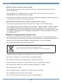
Disposal information for countries outside the European Union
This symbol is only valid within the European Union.
Contact the place of purchase or a distributor for advice on disposing.
• Charge the battery indoors to avoid exposure to rain or wind.
• Do not use outdoors or in environments with high humidity.
• Do not place the battery charger on dusty floors when using it.
• Place the battery charger on a stable surface such as a table when using it.
• Do not place any objects on top of the battery charger or its cable.
• Do not bundle the cables.
• Do not hold the battery charger by the cables when carrying it.
• Do not apply excessive tension to the cables.
• Do not wash the battery charger or wipe it using detergents.

20
TO ENSURE SAFETY
SM-BCR2: Battery charger/PC linkage device for SM-BTR2/BT-DN110/BT-DN110-A
• Connect the PC linkage device directly to the USB port on a PC, without using an
intermediate device such as a USB hub.
• Do not ride the bicycle while the PC linkage device and cable are still connected to it.
• Do not connect two or more of the same units to the same connection point. If this is not
done, the units may not operate correctly.
• Do not connect or disconnect the units again while unit recognition is in progress or after
recognition is complete. If this is not done, the units may not operate correctly.
Check the procedures which are given in the user's manual for the E-TUBE PROJECT when
connecting and disconnecting units.
• The tightness of the PC link cable will tend to drop after repeated connections and
disconnections. If this happens, replace the cable.
• Do not connect two or more PC linkage devices at the same time. If two or more PC
linkage device units are connected, they will not operate correctly. In addition, the PC
may need to be restarted if operating errors occur.
• PC linkage devices cannot be used while the battery charger is connected.
Rear derailleur
• If gear shifting operations do not feel smooth, wash the derailleur and lubricate all
moving parts.
• If the chain keeps skipping, ask the place of purchase to replace the gears and the chain.
• If there is a large gap in the pulleys which causes a lot of noise, ask the place of purchase
to replace the pulleys.
• The gears should be periodically washed with a neutral detergent. In addition, cleaning
the chain with neutral detergent and lubricating it can be an effective way of extending
the life of the gears and the chain.
• If looseness in the links is so great that gear shifting adjustments cannot be made,
replace the derailleur.
Hydraulic disc brake
• When the bicycle wheel has been removed, it is recommended that pad spacers are
installed. Do not depress the brake lever while the wheel is removed. If the brake lever is
depressed without the pad spacers installed, the pistons will protrude further than
normal. If that happens, consult the place of purchase.
• Use soapy water and a dry cloth when cleaning and carrying out maintenance of the
brake system. Do not use commercially available brake cleaners or silencing agents, as
they can cause damage to parts such as seals.
Page is loading ...
Page is loading ...
Page is loading ...
Page is loading ...
Page is loading ...
Page is loading ...
Page is loading ...
Page is loading ...
Page is loading ...
Page is loading ...
Page is loading ...
Page is loading ...
Page is loading ...
Page is loading ...
Page is loading ...
Page is loading ...
Page is loading ...
Page is loading ...
Page is loading ...
Page is loading ...
Page is loading ...
Page is loading ...
Page is loading ...
Page is loading ...
Page is loading ...
Page is loading ...
Page is loading ...
Page is loading ...
Page is loading ...
Page is loading ...
Page is loading ...
Page is loading ...
Page is loading ...
Page is loading ...
Page is loading ...
Page is loading ...
Page is loading ...
Page is loading ...
Page is loading ...
Page is loading ...
Page is loading ...
Page is loading ...
Page is loading ...
Page is loading ...
Page is loading ...
Page is loading ...
Page is loading ...
Page is loading ...
Page is loading ...
Page is loading ...
Page is loading ...
Page is loading ...
Page is loading ...
Page is loading ...
Page is loading ...
Page is loading ...
Page is loading ...
Page is loading ...
Page is loading ...
Page is loading ...
Page is loading ...
Page is loading ...
Page is loading ...
Page is loading ...
Page is loading ...
Page is loading ...
Page is loading ...
Page is loading ...
Page is loading ...
Page is loading ...
Page is loading ...
Page is loading ...
Page is loading ...
Page is loading ...
Page is loading ...
Page is loading ...
Page is loading ...
Page is loading ...
Page is loading ...
Page is loading ...
Page is loading ...
Page is loading ...
Page is loading ...
Page is loading ...
Page is loading ...
Page is loading ...
Page is loading ...
Page is loading ...
Page is loading ...
Page is loading ...
Page is loading ...
Page is loading ...
Page is loading ...
Page is loading ...
Page is loading ...
Page is loading ...
Page is loading ...
Page is loading ...
Page is loading ...
Page is loading ...
Page is loading ...
Page is loading ...
Page is loading ...
Page is loading ...
Page is loading ...
Page is loading ...
Page is loading ...
Page is loading ...
Page is loading ...
Page is loading ...
Page is loading ...
Page is loading ...
Page is loading ...
Page is loading ...
Page is loading ...
Page is loading ...
Page is loading ...
Page is loading ...
Page is loading ...
Page is loading ...
Page is loading ...
Page is loading ...
Page is loading ...
Page is loading ...
Page is loading ...
Page is loading ...
Page is loading ...
Page is loading ...
Page is loading ...
Page is loading ...
Page is loading ...
Page is loading ...
Page is loading ...
Page is loading ...
Page is loading ...
Page is loading ...
Page is loading ...
Page is loading ...
Page is loading ...
Page is loading ...
Page is loading ...
Page is loading ...
Page is loading ...
Page is loading ...
Page is loading ...
Page is loading ...
Page is loading ...
Page is loading ...
Page is loading ...
Page is loading ...
Page is loading ...
Page is loading ...
Page is loading ...
Page is loading ...
Page is loading ...
Page is loading ...
Page is loading ...
Page is loading ...
Page is loading ...
Page is loading ...
Page is loading ...
Page is loading ...
Page is loading ...
Page is loading ...
Page is loading ...
Page is loading ...
Page is loading ...
Page is loading ...
Page is loading ...
Page is loading ...
Page is loading ...
Page is loading ...
-
 1
1
-
 2
2
-
 3
3
-
 4
4
-
 5
5
-
 6
6
-
 7
7
-
 8
8
-
 9
9
-
 10
10
-
 11
11
-
 12
12
-
 13
13
-
 14
14
-
 15
15
-
 16
16
-
 17
17
-
 18
18
-
 19
19
-
 20
20
-
 21
21
-
 22
22
-
 23
23
-
 24
24
-
 25
25
-
 26
26
-
 27
27
-
 28
28
-
 29
29
-
 30
30
-
 31
31
-
 32
32
-
 33
33
-
 34
34
-
 35
35
-
 36
36
-
 37
37
-
 38
38
-
 39
39
-
 40
40
-
 41
41
-
 42
42
-
 43
43
-
 44
44
-
 45
45
-
 46
46
-
 47
47
-
 48
48
-
 49
49
-
 50
50
-
 51
51
-
 52
52
-
 53
53
-
 54
54
-
 55
55
-
 56
56
-
 57
57
-
 58
58
-
 59
59
-
 60
60
-
 61
61
-
 62
62
-
 63
63
-
 64
64
-
 65
65
-
 66
66
-
 67
67
-
 68
68
-
 69
69
-
 70
70
-
 71
71
-
 72
72
-
 73
73
-
 74
74
-
 75
75
-
 76
76
-
 77
77
-
 78
78
-
 79
79
-
 80
80
-
 81
81
-
 82
82
-
 83
83
-
 84
84
-
 85
85
-
 86
86
-
 87
87
-
 88
88
-
 89
89
-
 90
90
-
 91
91
-
 92
92
-
 93
93
-
 94
94
-
 95
95
-
 96
96
-
 97
97
-
 98
98
-
 99
99
-
 100
100
-
 101
101
-
 102
102
-
 103
103
-
 104
104
-
 105
105
-
 106
106
-
 107
107
-
 108
108
-
 109
109
-
 110
110
-
 111
111
-
 112
112
-
 113
113
-
 114
114
-
 115
115
-
 116
116
-
 117
117
-
 118
118
-
 119
119
-
 120
120
-
 121
121
-
 122
122
-
 123
123
-
 124
124
-
 125
125
-
 126
126
-
 127
127
-
 128
128
-
 129
129
-
 130
130
-
 131
131
-
 132
132
-
 133
133
-
 134
134
-
 135
135
-
 136
136
-
 137
137
-
 138
138
-
 139
139
-
 140
140
-
 141
141
-
 142
142
-
 143
143
-
 144
144
-
 145
145
-
 146
146
-
 147
147
-
 148
148
-
 149
149
-
 150
150
-
 151
151
-
 152
152
-
 153
153
-
 154
154
-
 155
155
-
 156
156
-
 157
157
-
 158
158
-
 159
159
-
 160
160
-
 161
161
-
 162
162
-
 163
163
-
 164
164
-
 165
165
-
 166
166
-
 167
167
-
 168
168
-
 169
169
-
 170
170
-
 171
171
-
 172
172
-
 173
173
-
 174
174
-
 175
175
-
 176
176
-
 177
177
-
 178
178
-
 179
179
-
 180
180
-
 181
181
-
 182
182
-
 183
183
-
 184
184
-
 185
185
-
 186
186
-
 187
187
-
 188
188
-
 189
189
-
 190
190
-
 191
191
-
 192
192


Shimano BT-DN110 Dealer's Manual
- Category
- Bicycles
- Type
- Dealer's Manual
Ask a question and I''ll find the answer in the document
Finding information in a document is now easier with AI
Related papers
-
Shimano CS-HG50-6ad Exploded View
-
-
Shimano DI2 Battery Charger User manual
-
Shimano SM-EW90 User manual
-
-
Shimano FD-M3120 Dealer's Manual
-
Shimano RD-RX805 User manual
-
Shimano SW-R671 User manual
-
-
Shimano FD-M4100 Dealer's Manual
Other documents
-
 No Drilling Required DK220-CHR Installation guide
-
BodyCraft SP-Tablet/Phone Holder Operating instructions
-
 Ceramicspeed OSPW X for Shimano RX/GRX User manual
-
 Ceramicspeed OSPW X for Shimano RX/GRX User manual
-
 Cervélo RCA Supplementary Manual
-
 NexSens CM-500 User manual
-
Cannondale Coda Brakes Owner's manual
-
PyleHome PMKSPAD4LK Owner's manual
-
 Ceramicspeed OSPW X for Shimano XT/XTR 1×12 User manual
-
Pioneer XW-SMA3 User manual


