Page is loading ...

INSTALLATION AND USER INSTRUCTIONS
All instructions must be handed to user for safekeeping
Revision A - 08/05
Country(s) of destination - GB/IE
AFINA
FAN FLUE GAS FIRE
CK Fires Ltd. 1 Stour House, Clifford Park, Clifford Road,
Stratford Upon Avon, CV37 8HW
Tel : 01789 290 999 Fax : 01789 290 998

INSTTALLATTION IINSTTRUCTTIONS
PPrelimminnary NNotes BBefore IInnstallationn
This appliance is an Inset Live Fuel Effect appliance which provides radiant
warmth utilising the latest type burner technology.
The fire is designed to suit various types of fireplaces and installation methods
as detailed in this manual.
The appliance must be installed by a competent person in accordance with
Gas Safety (Installation and Use) Regulations 1998. It is strongly recommended
that a CORGI registered engineer be used for this purpose.
Read all these instructions before commencing installation.
This appliance must be installed in accordance with the rules in force and used
only in a sufficiently ventilated space.
The appliance is designed for installation on to a non-combustible hearth of at
least 300mm depth.
This appliance is factory set for operation on the gas type, and at the pressure
stated on the appliance data plate.
This appliance is available with a number of fuel effect options. These instruc-
tions cover all fuel effect options. See the relevant sections of these instructions
for further details.

IMPORTANT NNOTES
This fire is an Inset Live Fuel Effect Gas Fire providing radiant warmth. It is designed to operate on Natural Gas
only.
It is the LAW that all gas appliances and fittings are installed by a registered competent person (such as a CORGI
registered fitter) and in accordance with the Gas Safety (Installation and Use) Regulations 1998, the relevant
British Standards for Installation, Codes of Practice and in accordance with the Manufacturers’ Instructions. The
installation shall also be carried out in accordance with the following regulations:
The Building Regulations issued by the Department of the Environment, the Building Standards (Scotland)
(Consolidation) Regulations issued by the Scottish Development Department.
BS 5871 part 2
BS 5440 part 1
BS 6891
BS 6461 parts 1 and 2
BS 3456 part 201
BS-EN 60335
Failure tto ccomplyy wwith tthese rregulations ccould llead tto pproseccution aand ddeem tthe wwarrantyy
invalid.
Consult aall iinstrucctions bbefore iinstallation aand uuse oof tthis aappliancce.
This aappliancce iis ffree ffrom aanyy aasbestos mmaterial. RRefracctories aand ccoal bbed aare cconstruccted
from cceramicc ffibre.
1
Secction
1.0
2.0
3.0
4.0
5.0
6.0
7.0
7.1
8.0
8.1
8.2
8.3
8.4
8.5
8.6
8.7
Contentss
Important Notes
Appliance Data
Installation Requirements
Terminal Location
Site Requirements
Ventilation
Unpacking the Appliance
Component Checklist
Preparing for Installation
Outer Wall Aperture
Gas Supply Routing
Installation Method 1
Installation Method 2
Installation Method 3
Flue Preparation
Firebox and Tray
Pagge NNo.
1
2
2
3
4
5
5
5
5
6
6
7
8
9
11
11
Secction
8.8
9.0
10.0
11.0
11.1
11.2
11.3
11.4
11.5
12.0
13.0
13.1
13.2
13.3
13.4
14.0
Contentss
Fitting Fan Terminal
Fuel Bed Layout
Fitting Frame and Front
Testing & Commissioning
Operating the Appliance
Spark Failure
Setting Pressure
Spillage Monitoring System
Testing for Spillage
Briefing the Customer
Servicing
Cleaning the Ceramics
Dismantling the Burner Tray
Checking the Fan Assembly
Control Box Removal
Troubleshooting Guide
Pagge NNo.
11
13
16
16
17
17
17
17
18
18
19
19
19
20
20
21
Note - FFor RRepublicc oof IIreland, rreferencce
sshould bbe mmade tto tthe rrelevant sstandardss
ggoverningg iinsstallation, pparticcularly iin rreggard
to fflue ssizingg aand vventilation. SSee IIS813,
ICP3, IIS3277 aand aany oother rruless iin fforcce.
1.0

INSTALLATION RREQUIREMENTS
Compatible wall thicknesses for the Installation Methods detailed in this Guide are as follows;
Note: TThesse ddimenssionss aare bbetween tthe ssurfacce oof tthe mmarble/bacckpanel aand tthe ssurfacce oof tthe ooutsside wwall.
IInntteerrnnaall
This appliance MUST NOT be installed into a room containing a bath or shower, or where steam may be
present. The firebox must be installed onto a suitable non-combustible insulating surface at least 12mm thick,
covering the entire base are of the box. This appliance is suitable for use with a “lightweight” surround and back
panel of 150ºc minimum rating. A suitable gas supply and an electrical 3 Amp fixed fused spur are both required
near the intended appliance site.
EExxtteerrnnaall
Please refer to the diagram on the following page for more details of the most suitable site for the fan terminal.
The terminal must be located so that the outlet is not obstructed in any way allowing poor disposal of
combustion products. A safety cage should be fitted in place over the terminal to ensure compliance with
Byelaws. Terminals located in passageways between two properties, public footpaths or which might discharge
over the same may be subject to local Byelaws on items such as minimum distances for projection. In these
circumstances it is the installers responsibility to check that the location of the terminal does not infringe any
Byelaws. If in any doubt about flue terminal location, especially with regards to garages and car ports then further
advice should be sought from CORGI or the manufacurer.
2
APPLIANCE DDATA
Gas Group G20 Natural Gas CAT I2H
Inlet Pressure 20 mbar
Max Energy Input (gross) 6.8 kW
Min Energy Input (gross) 3.5 kW
Pilot Energy Input (gross) 210 W
Setting Pressure 15.8 mbar (+/- 0.75mbar)
Main Injector Burner Stereo size 81
Gas Inlet Connection 8mm compression
Ignition Piezo spark
Spark Gap 3.5 to 4.5mm
Electrical Supply 230V~50Hz (ac)
Current Rating 0.3A running, 0.4A on start up
Fuse Rating 3 Amp
Approximate Weight Fire Unit 20Kg, Fan Unit 12Kg
Flue Specification Twin walled circular section flue tube provided
with appliance. No additional or alternative flue
may be used. Outer flue tube diameter 120mm
See Data Badge affixed to appliance for current data.
This aappliancce iis ffor uuse oonlyy wwith tthe ggas ttyype, aand aat tthe ppressure sstated oon tthe aappliancce
Data BBadge, aand iis ffor ddeccorative ppurposes.
2.0
3.0
* These dimensions allow for 25mm Rockwool insulation jacket,
other forms of insulation may require adjustment.
Surface mounted firebox/surface mounted fan terminal.* 60mm 560mm
Surface mounted firebox/recessed fan terminal.* 150mm 650mm
Recessed firebox/surface mounted fan terminal. 265mm 765mm
Recessed firebox/recessed fan terminal. 355mm 855mm
Min Max

INSTALLATION REQUIREMENTS ((continued)
Avoid locating the terminal in close proximity to combustible materials, such as plastic drainpipes and fences. If
these are impossible to avoid, then a suitable metal deflector must be used if the flue gasses begin to heat the
object. For minimum standard dimensions of clearance see below.
Covered areas such as under car ports should be avoided but if no alternative is available the following notes
should be adhered to; The covered area should have at least two open sides (i.e. a roof and ONE supporting wall).
If more than one side is filled, then advice must be sought on the location’s suitability. Any openings into
dwellings such as doors, windows and air vents under the covered area must be at least 1200mm away from the
terminal position. If the roof is constructed from plastic material, great care must be taken with the installation as
there is no simple method of protecting this type of roof from heat build up.
TERMINAL LOCATION
MMiinniimmuumm llooccaattiioonn ddiissttaanncceess
A - 300mm above ground level/roof or balcony level.
B - 200mm below balconies or car ports.
C - 1500mm vertically between terminals.
D - 300mm horizontally between terminals on same wall.
E - 75mm below gutters, soil pipes or drain pipes.
F - 200mm below eaves.
G - 300mm from internal or external corners
H - 150mm from vertical drain pipes.
J - 300mm directly below an openable window or other opening e.g. air vent.
K - 1200mm from an opening into the building under a car port.
L - 600mm from a surface facing the terminal.
M - 1200mm from another terminal facing the terminal.
Care should also be taken with the terminal location relative to nearby plants, grass, or trees as the gases expelled
may be hot enough to damage them. At least 1000mm clearance is recommended.
Note: DDimenssionss rrelate sspeccificcally tto tthe eexhausst ooutlet aat tthe bbasse oof ffan tterminal bbox.
3
3.0
E
H
D
C
G
G
A
J
B
K
L/M
*a suitable metal
deflector may be
required where
plastic pipes are
involved.
Metal deflector plate with
min. 5mm air gap.
4.0
F

SITE RREQUIREMENTS
For aesthetic purposes it is essential that the hearth and infill plinth area are flat and level. The hearth and infill
must also be square to the back panel. Failure to comply with this could cause the appliance to lean away from
the fireplace resulting in an unsatisfactory installation.
The electrical earth to the property and all wiring must be carried out in accordance with IEE Wiring Regulations
(including any Local Regulations). If you are unsure about this aspect, then professional advice should be sought.
This appliance is suitable for use with a 230V~50Hz (ac) single phase (normal domestic) electrical supply.
Connection to the mains supply should be made with the three core cable (green/yellow -earth, blue - neutral,
brown - live) to a fixed fused spur with double pole insulation (minimum 3mm separation of poles) and fused at
3 amp. Take care not to pull or damage the internal wiring to the the fan unit at any time during installation.
Should the mains cable become damaged at any stage, it should only be replaced with the manufacturers sup-
plied cable (part no. EL006225/0). Failure to use a genuine spare could cause a hazard.
WWAARRNNIINNGG!! TTHHIISS AAPPPPLLIIAANNCCEE MMUUSSTT BBEE EEAARRTTHHEEDD..
If a concealed gas supply is to be used, the supply pipe must be sleeved through walls and floors. If the fire is to
be inset into the cavity leaf, only factory sleeved pipe should be used. For further details see relevant section. A
separate isolation device must be incorporated into the incoming gas supply to facilitate servicing. No more than
1.5 metres of 8mm pipe should be used in the connection of the gas supply to the appliance, as more could result
in an unacceptable drop in pressure.
This appliance must only be installed onto a non-combustible wall or surface. The fire requires a hearth with a
non-combustible surface at least 12mm thick. The top surface of the hearth must be at least 50mm above floor
level, or be surrounded by a raised edge or fixed fender of at least 50mm high. The non-combustible hearth must
extend a minimum of 300mm in front of, and 150mm either side of the live part of the appliance. The hearth must
therefore be a minimum of 680mm wide.
The appliance must be installed by one of the following methods;
1 - Fitment against an existing inner house wall with a suitably constructed fireplace and/or false
chimney breast to enclose the depth of the fire.
2 - Insertion into a purpose made opening in the inner leaf of a cavity wall or disused fireplace opening
with the use of a suitable fireplace surround etc.
Note: TThe aappliancce mmusst nnot bbridgge tthe ccavity - aany
overhangg bbeingg kkept tto aa mminimum, aand tthe IInsstallation iinsstrucctionss mmusst bbe aadhered tto. BBuildingg
Control rrequirementss mmay vvary iin ssome aareass, eenquiriess sshould bbe mmade aaccccordinggly.
3 - Installation into a timber framed dwelling using the clearances to combustible materials shown in the
relevant section. Building Control requirements vary in some areas, enquiries should be made
accordingly.
An unprotected combustible shelf may be fitted above the appliance, provided it complies with the minimum
dimensions stated below. Protective materials can be used to deflect heat from shelves that are too low.
A non-combustible shelf may be fitted to within 10mm of the top edge of the fireframe. Combustible materials,
such as wood, may be fitted to within 100mm (4in) of either side of the frame of the firebox providing it projects
no further forward than 100mm (4in). As with all heating appliances, decorations, soft furnishings and wall
coverings (such as blown vinyl, flock and embossed paper) may discolour or scorch if positioned too close to the
fire. If the appliance is fitted to a dry-lined wall, the gap between the plasterboard and blocks must be sealed with
non-combustible material and any unplastered board replaced with superlux or other non-combustible material
if in direct contact with the appliance.
4
5.0
Maximum ddepth oof sshelf MMinimum ddisstancce ffrom ffinisshed hhearth
ssurfacce tto uundersside oof sshelf
100mm (4in) 745mm (29 1/4 in)
150mm (6in) 845mm (33 1/4 in)
203mm (8in) 895mm (35 1/4 in)

VENTILATION
No purpose provided ventilation is normally required with this appliance. However, the ventilation requirements
of other gas appliances in the same room or space should be taken into consideration. A spillage test should be
carried out as described in the relevant section with the doors and windows both open and closed, and with any
extractor fan running on full. Where fitted, ventilation must comply with the requirements of BS 5440 part 2.
Vents directly underneath or within the immediate vicinity of appliances
musst nnot
be used as they may
adversely affect ODS pilot operation.
Note: FFor RRepublicc oof IIreland ssee IIS813, IICP3 aand IIS3277 aand aany oother rruless iin fforcce.
UNPACKING TTHE AAPPLIANCE
Stand the carton right way up, cut the strapping bands and remove the top end cap. Read all the instructions
before continuing to unpack or install this appliance.
Remove the box containing the fire front, and the boxes containing the ceramics. Remove the cardboard pack-
ing pieces, and any bags containing other fittings or parts. When all loose parts have been removed, the outer
sleeve may be lifted off to reveal the appliance.
Check that the components supplied correlate with the checklist given in section 7.1.
Please dispose of the packaging materials at your local recycling centre.
COMPONENT CHECKLIST
QUAANTITY DESCRIPTION QUAANTITY DESCRIPTION
1 Firebox and burner tray assembly 1 Fan assembly
1 Decorative fireframe 1 Twin-walled tubular flue
1 Fire front with separate ashpan cover 1 Rockwool jacket
1 Moulded ceramic fibre combustion matrix 1 Terminal guard cage
1 Front ceramic strip 1 Fan box trim
1 Bag of 16 moulded ceramic coals (coal versions only 1 Fan box cover
1 Bag of 16 ceramic pebbles (pebble versions only)
1 Set of manufacturers instructions
1 Bag of fixings (10 rawl plugs, 10 No8x1.5 screws, 4 No8x0.5 screws), 3 lengths of sealing strip
3 Ceramic radiant panels
PREPARING FOR INSTALLATION
Remove the fire tray from the firebox by removing the two
securing screws in the front legs of the tray and invert the
tray. Carefully unplug the safety solenoid on the tray from
the control box by squeezing the clip on the three way con-
nector and easing apart. Place the tray safely to one side
along with the fuel bed components, firefront and decora-
tive frame.
The three radiant panels may now be fitted inside the fire-
box. Select the patterned side of the panels and insert as fol-
lows; Lay the firebox on it’s back. Lay the tapered panel onto
the rear face of the firebox. The side panels should be fitted by inserting their front
edges into the pre-fitted retaining brackets on the front face of the firebox. Gently
align the side panels with the sides of the firebox, over the back panel already in
place. Make sure that the side panels are pushed
up
firmly to the roof of the fire-
box, and
bacck
firmly to retain the rear panel. Make small adjustments to line up the
mortar lines if required. Clamp the side panel using the ‘L’ shaped brackets and
screws provided. The screws should locate into the holes in the sides of the firebox.
5
6.0
8.0
7.0
7.1

PREPARING FOR INSTALLATION ((continued)
Apply the self adhesive sealing strip to the rear perimeter of the firebox frame so as not to be visible. This will
eventually seal the firebox to the fireplace back panel. Place the fire to one side whilst the site is prepared for flue
installation. Mark the vertical centreline of the desired
location of the appliance after first checking for clearances
to pipes and cables in the wall, and also the terminal posi-
tion outside.
Note: TThe vverticcal ccentreline oof tthe ppilot hhole wwill bbe
500mm ffrom tthe ffloor PPLUS the tthiccknessss oof tthe hhearth
you aare uussingg. TThiss ddimenssion iiss oobvioussly FFROM the
hearth ttop ssurfacce iif iit iiss aalready ffitted
Mark the position of the 30mm cable hole in relation to
the flue centreline. Using a suitably long masonry bit, drill
through both leaves of the cavity wall. Check outside that
the clearances from the hole are adequate for installation
to proceed. Check all dimensions with the diagram in the
relevant section. Now drill the 30mm cable hole in the
wall.
OUTER WALL APERTURE
From the outside of the property, open up the pilot hole in the
external leaf of the cavity to the required size.
If the fan terminal is to mounted directly onto the outside wall,
the hole should be opened up to a 125mm diameter aperture
centred around the pilot hole.
If the fan terminal is to be recessed into the outer leaf, the hole
should be opened up to the dimensions given in the diagram.
Clear all the brick rubble and debris that may have fallen into the
cavity. If the cavity wall insulation is obstructing your view of the
inner leaf then clear this back.
GAS SUPPLY ROUTES
The gas supply may enter the appliance across the hearth or through the ‘knock outs’ provided in the rear of the
firebox. Gas pipes should not be buried or routed through walls without being protected by conduit or sleeving.
An isolation tap must be included in the gas connection pipe to facilitate servicing.
Note: AAny ffittinggss uussed uunderneath tthe aappliancce
musst bbe rrated tto 880
o
C aand mmusst nnot ccome iinto ccon-
tacct wwith tthe uundersside oof tthe bburner uunit
For INSTALLATION METHOD 1, the gas supply can
be run in the conventional manner taking due
account of rules and regulations.
For INSTALLATION METHOD 2, use only factory
sleeved pipe in a continuous unjoined length in the
cavity of the wall and area which communicate with
the cavity. Ensure a good seal where the pipe enters
through the appliance grommet. This is a permitted
gas supply routing.
6
8.1
8.0
Proposed location of appliance
120mm
500mm
plus
thickness of
hearth
Centreline of flue
Cable routing hole
257-267mm
297-
307mm
118mm
105mm
Pilot hole
139mm
192mm
Cavity
Outer leaf
Fireplace panel
Firebox
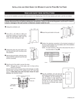
8.2

INSTALLATION METHOD 11
Thiss mmethod rrequiress mminimal mmodificcation tto tthe pproperty’ss wwall aand iiss aacchieved uutilissingg eeither aan eextended ffiress-
urround oor bby cconsstrucctingg aa sshallow ffalsse cchimney bbreasst oof aa mminimum 1180mm ddeep. SSee ddiaggram ffor ffurther
dimenssionss.
Centering on the pilot hole already drilled, create a hole from inside the property 125mm diameter. If the prop-
erty has loose fill cavity wall insulation fitted, it will be necessary to seal the wall cavity where the flue opening is
formed to prevent insulation material coming into contact with hot surfaces of the fire and it’s components. The
recommended method is to pack a depth of 50-100mm of Rockwool or a similar non-combustible insulation
material into the cavity .
Where the property does not have existing cavity wall insulation, it is still recommended that a space 50-100mm
into the cavity is packed with Rockwool or similar material, to prevent any future installation of cavity wall
insulation from coming into contact with hot areas of the appliance.
At this point the false chimney breast or fire surround should be installed.
Note: WWhen cconsstrucctingg tthe sstud ppartition, aall uuninssulated, ccombusstible mmaterial mmusst bbe kkept aa mminimum oof
775mm aaway ffrom tthe ffireplacce. CCombusstible mmaterialss cclosser tthan 775mm MMUST bbe pproteccted wwith aa mminimum
of 225mm iinssulation mmaterial.
77
8.3
Rockwool Insulation
Outer cavity leaf
Inner cavity leaf
False chimney breast
Fireplace backpanel
B
C
E
G
A- Opening width: 375mm min. 460mm max.
B- Overall width: 480mm
C- Overall height (excluding hearth): 590mm.
D- Opening height: (excluding hearth): 565mm min. 580mm max.
E- Recessed depth of fire: 180mm
F- The hearth must extend 300mm in front of the appliance, with it’s top surface 50mm above the surround-
ing floor level or having a 50mm high fixed fender around it’s perimeter.
G- Space allowed for Rockwool jacket: 25mm
A
D

INSTALLATION METHOD 2
This method allows for installation of the appliance with the rear part of it's firebox recessed into the inner leaf
of the cavity wall. This will enable a standard fireplace to be flush fitted to the wall and the appliance will then
be fitted flush into the fireplace. The structural integrity of the wall must be maintained.
Check on the type of cavity insulation used, and if it is of the granular type then take suitable precautions when
opening up the wall not to allow excessive loss of insulation material from the cavity. Packing the cavity with
Rockwool should help hold back loose fill insulation material.
Unless lime and mortar has been used, it will be necessary to drill four holes with a masonry, drill, and then use
a mechanical cutter (Sharksaw) to cut out the correct size of 'slot' required for the chosen lintel.
NOTE: Obtain a lintel 750mm long x 75mm deep x thickness of the inner leaf. We would suggest either a pre-
cast concrete or steel lintel; Catnic CN52 or CN46 depending on thickness. Typical inner leaf weights when siz-
ing a lintel over a 450mm wide opening are 90kg for 100mm blockwork and 120kg for 125mm blockwork.
Plan to minimise disruption to occupants and protect any other parts of the building against dust infiltration.
Areas that are opened up will need to be protected against rain or snow during the work and if there is a risk of
frost, replacement brickwork will require protection until mortars have hardened.
Set out where possible centrally beneath a block join as
shown. Use a drill for guide holes, and a 'shark saw' or angle
grinder to form an opening to suit the lintel.
The lintel should be inserted and securely slate pinned,
leaving the wall above safe and firm.
Note: AAlwayss bbed oon mmortar, DDO NOT ddry bbed.
Remove all masonry from below the lintel, and clear debris
from the cavity.
The top of the exposed cavity must be sealed with Superlux
board or a similar non-combustible material. The board
should be fixed at an angle, lower at the back, so as to direct
any moisture coming down to the outside wall. This board
should be fixed with screws, Unibond, or a similar adhesive.
It is important to fit this board or a cavity tray to protect the
property and the appliance from drips of water. The sides of
the opening where the cavity is exposed should be packed
with Rockwool or similar non-combustible material to a min-
imum depth of 50mm. The Rockwool packing must extend
from the base of the opening to the Superlux board.
The non-combustible hearth should now be formed or secured in place.
8
8.4

INSTALLATION METHOD 2 ((continued)
It is essential the Rockwool pad be fitted to the rear of the appliance to prevent condensation and to insulate
the appliance firebox from the cold air of the cavity.
Note: NNeither tthe aappliancce nnor tthe RRocckwool iinssulatingg ppad sshould bbridgge tthe ccavity. CConssult yyour lloccal
Buildingg CControl DDepartment ffor aany aadditional cconsstrucction rrequirementss oor ffurther aadvicce.
INSTALLATION METHOD 3
IInnssttaallllaattiioonn iinnttoo ttiimmbbeerr ffrraammeedd ddwweelllliinnggss
Where removal of any part of the inner timber leaf of the wall is involved, the structural integrity of the wall must
be maintained and the advice of your local Building Control Department should be sought. If the property is
under any N.H.B.C. cover, it is advised that their advice on this modification should also be sought.
Either of the two preceding methods of installation may be adapted for use in timber framed buildings, providing
extra care is taken to prevent combustible materials from contact with hot surfaces.
The appliance must be installed in accordance with British Gas documents DM2 and DM3 or the Institute of
Gas Engineers published procedure IGE/UP/7.
Special attention must be paid to the location of the studwork frames of the inner leaf and the appliance
positioned accordingly. Wires and pipes that run within the inner timber leaf must also be located and taken into
account when positioning the appliance.
9
Outer cavity leaf
Inner cavity leaf
Lintel
Superlux board
Fireplace backpanel
B
A
C
D
F
E
A- Opening width: 375mm min. 460mm max.
B- Overall width: 480mm
C- Overall height (exc hearth): 590mm.
D- Opening height: (exc hearth): 565mm min. 580mm max.
E- Recessed depth of fire: 180mm
F- The hearth must extend 300mm in front of the appliance, with it’s top surface 50mm above the surrounding
floor level or having a 50mm high fixed fender around it’s perimeter.
8.4
8.5

INSTALLATION METHOD 33 ((continued)
Insstallation uussingg rrebated ffire ssurround oor ffalsse cchimney bbreasst.
When using this method of installation the
following amendments should be incorporated.
25mm clearance must be allowed from the
appliance firebox to any insulated combustibles.
75mm clearance must be allowed to any unpro-
tected combustibles. 50mm minimum thickness
of insulation should be provided around flue
pipe and gather hood. Where the flue pipe pass-
es through the inner leaf, a hole 100mm larger
than the flue should be cut to allow 50mm air
gap around the entire flue circumference.
The vapour barrier on the back of the inner leaf
should be cut and carefully fixed to prevent any
ingress of damp into the plasterboard layer. A
layer of insulation will need to be provided to
insulate the surface of the inner wall from the
heat effect of the flue. It may be advantageous to
use a sheet of Superlux board for this purpose.
Insstallation bby ssettingg tthe aappliancce iinto tthe iinner lleaf oof wwall.
When setting the appliance into the inner wall find a suitable position between the wall panel frames and
carefully open up a hole to the dimensions given in the relevant section, paying careful attention to securing the
damp proof membrane back into position. A drip collar of galvanised or stainless steel should be formed with the
twisted joint on the underside of the flue to disperse drips.
An air gap of 75mm between all hot surfaces and the surrounding wall should be allowed, if protective insulation
is used this may be reduced to 25mm clearance. The exposed cavity should be sealed off using Superlux or a
similar non-combustible board, see below.
Note: NNeither tthe aappliancce nnor tthe RRocckwool iinssulation sshould ooverhangg tthe ccavity sspacce.
10
Superlux board
Wire drip collar formed around flue tube
8.5

FLUE PREPARATION
When all the preparation work has been completed for whichever method of installation has been chosen, and
with the fire surround fitted, take the appliance and slide the round flue section over the spigot on the rear of the
fire. Protect any decorative hearth with a dust sheet or similar, place the appliance in position with the flue
section protruding through the wall(s) to the outside. Make sure the firebox is fully pushed home before marking
two fixing holes in the base of the firebox. Outside the property, mark a line on the flue tube level with the outer
surface of the wall, where it protrudes through.
Remove the firebox from the location and slide off the flue section. If the fan terminal is to mounted directly on
the the outside wall, cut the flue tube to length along the marked line.
If tthe tterminal iiss tto bbe rreccessssed iinto tthe
outer wwall, aa sseccond lline sshould bbe mmarked 885mm bbacck ttowardss tthe aappliancce.
The flue tube should then
carefully be cut to length along the relevant line. Do not remove the ceramic insulation. File off any rough edges
and slide back on to the appliance spigot ensuring the ‘O’ ring remains seated in its channel. Slide the Rockwool
jacket into place over the flue section, this may be secured with aluminium tape.
With a suitable drill bit, make the two previously marked holes in the base of the firebox, drilling down through
into the non-combustible hearth. Fit two rawl plugs into the holes.
FIREBOX AND BURNER TRAY
The mains electrical supply cable exits from the rear of the appliance and the FIXED FUSED SPUR (fused at 3
Amp) should be arranged to allow easy connection.
Stand the appliance in front of the opening and feed the fan wiring harness through the hole drilled in the wall.
You may find this easier if a short length of plastic conduit is first fitted to the hole. The cable must run outside
of the insulating jacket, and be arranged so that is does not touch any hot surfaces. Feed the mains cable through
to the location of the fixed fused spur. Depending on the location of the 8mm gas supply, feed through the back
of the firebox and fit the grommet seal (if applicable). Now carefully slide the appliance back into position and
secure into place using the two previously drilled holes. Ensure the flue unit has passed correctly through the wall.
Note: IIf uussingg aan oover hhearth ggass ssupply, tthe rroute oof tthe ppipe sshould bbe lloccated tthrouggh tthe ppurposse pprovided
ccutoutss ((if aappliccable)) oon tthe ddeccorative ffirefront ssupplied wwith tthe aappliancce.
Place the burner tray near to the firebox and connect the three-way plug from the control box to the safety
solenoid mounted on the burner. Connect the gas supply to the entry point on the gas valve. Secure the burner
tray into position with the two screws though the burner legs.
FITTING THE FAN TERMINAL
The external fan terminal can now be fitted. This comprises three parts, the wall fan box section, the cover and
the trim frame (only used for recessed mounting). At this point, the trim must be fitted to the fan box unit if the
terminal is to be recessed into the wall. Remove the four self tapping screws from the sides of the fan box, and
slide the trim frame over the box with the fixing flanges facing into the wall. Secure with the four screws and pro-
ceed to fit the terminal as described below.
Offer up the fan unit and feed the connecting cable through the entry hole in the wall plate. It may be
advantageous to remove the rubber grommet in the entry hole to aid insertion of the wires and refit afterwards.
Run the connectors through the entry hole, then feed them through the grommet, before finally refitting the
grommet to the entry hole.
Note: TThe ggrommet MMUST bbe rrefitted iin oorder tto pprevent ddamagge tto tthe ffan wwiringg hharnessss.
Insstallingg tthe ffan tterminal bby ssurfacce mmountingg oon tthe ooutsside wwall
Slide the fan unit on to the previously installed flue pipe. Mark the four fixing screw positions on the wall, and
drill the 5mm securing holes into the brickwork. Affix the fan terminal to the wall with the rawl plugs and screws
provided. A bead of silicone weather sealant, or similar suitable sealant should be applied along the top edge,
and down the two sides of the terminal where it meets the wall, to prevent the ingress of water. Any excess sealant
should be wiped away.
11
8.6
8.7
8.8

FITTING THE FAN TERMINAL ((continued)
Fittingg tthe ffan tterminal bby rreccessssingg iinto tthe oouter wwall
If already fitted, remove the four long M4 screws from the top and bottom of the fan terminal. Fit the terminal
into the wall opening previously prepared, ensuring the flue tube seats correctly over the terminal spigot. When
correctly fitted, insert the four screws into the threaded inserts fitted to the inside of the top and bottom of the
terminal. Using a suitable screwdriver, continue to wind in the four screws from the inside of the box until the fan
terminal is held securely in the opening. Alternatively, four holes may be marked in the sides of the fan terminal,
and these drilled through into the brick work. The terminal can then be secured with wall plugs and screws. Apply
a bead of silicone weather sealant, or similar suitable sealant around the top and side edges of the frame to
provide a good seal to the wall, eliminating water ingress.
Note: TThe rreccessssed ffan tterminal MMUST NOT bbe ccemented iinto pplacce wwithin tthe oouter wwall. TThe llouvress iin tthe
ssidess oof tthe ffan tterminal MMUST bbe aallowed tto vvent tto tthe ccavity tto aaid ccoolingg oof ccomponentss wwithin.
With the terminal fixed into position the wires may now be connected. Attach the green earth wire to the screw
securing the fan earth wire. Fit the two three way connector to the relevant connectors from the fan unit and
pressure switch. Check that none of the wires can come into contact with hot surfaces or moving parts of the
fan. Use the cable tie supplied to secure the wires to the terminal. With all the cables properly connected, fit the
terminal cover ensuring the fan outlet is clear, and secure with the four screws provided. Offer the wire terminal
guard cage into position, mark and drill the relevant mounting holes, and secure into place using rawl plugs and
screws. The terminal guard should be fitted at all times to comply with any Byelaws in force.
SScchheemmaattiicc wwiirriinngg ooff ffaann uunniitt
12
Terminal ssurface mmounted oonto ooutside wwall
Terminal rrecessed iinto ooutside wwall
Seal along top and sides of terminal
Seal around the top and sides of frame
Fan
Pressure Switch
Thermal Switch
Earth
Three-way connectors
To appliance
BLACK
YELLOW
RED
8.8
Screw
outwards
to secure
fan box
into wall
aperture

GAS CONNECTION
Refit the burner tray into the firebox, fit the two
screws through the locating holes in the tray legs,
and tighten.
Purge the gas supply thoroughly to remove air and
dirt/debris
BEFORE
connection. Now disconnect the
inlet restrictor elbow from the inlet pipe. Connect the
previously installed gas supply to inlet restrictor
elbow, and re-fit the restrictor elbow to the inlet pipe
of the appliance.
If the data/control plate is not already fitted, attach with two screws, ensuring the control knob is free to be
depressed fully.
FUEL BED LAYOUT
Coal EEffect OOption
1. Remove the combustion matrix from its protective
packaging, and position onto the burner tray as
shown. The front edge of the matrix should sit snugly
behind the back edge of the burner rails. Do not fit the
matrix on top of the burner rails.
2. Next, remove the front coal strip from its protective
packaging and position as shown. The rear edge of the
front coal strip should fit in front of the burner rail.
Again, do not to place on top of the burner rails. When
the front coal is in position bend up the three metal
tags at the front of the tray to retain (inset).
13
8.9
Correct
Incorrect
9.0

FUEL BED LAYOUT ((continued)
3. Open the bag of 16 moulded coals. All of the coals
are the same. Take five coals and place them as
shown. Care should be taken to ensure that the coals
bridge the gap between the front coal and the four
coal supports at the front of the matrix. Care should
also be taken not to push the coals right down
between the coal supports, as this can detract from
the flame picture when the appliance is running.
4. Take five more moulded coals and position as
shown to form the ‘second row’ of the fuel effect. The
coals may be rotated as desired to fit into the gaps
between the coal supports in order to create a ran-
dom, realistic effect. Again, remember not to push the
coals down too far into the valleys between the coal
supports as this can have a detrimental effect to the
flame picture.
5. Now take another four coals and place behind the
second row of coals, in order to complete the third
row. The coals may be orientated as desired to
achieve a realistic effect. Keep the spacing between
the coals even and uniform. The two coals at the ends
of the row may be placed rearwards, towards the
back corners of the fuel matrix.
6. Finally, take the two remaining coals and place at
the back of the fuel matrix, in the centre as shown.
Adding these coals should complete the appearance
of the fuel bed giving an even distribution of equally
spaced coals.
The fire is designed to operate correctly with the coals
supplied when assembled according to the instruc-
tions. Never add to the sixteen coals, or change them
for a different type. Never throw rubbish or other mat-
ter onto the coal bed.
14
9.0

FUEL BED LAYOUT
Pebble EEffect OOption
1. Refer back to section 12.0 - Fuel bed layout (coal
effect option) and follow steps 1 and 2. The front strip
and fuel effect matrix used for pebble effect versions
are of the same design as coal effect versions, but
have a different surface finish.
2. Open the bag of 16 ceramic pebbles. All of these
pebbles are the same. Take five pebbles and place
them as shown. Care should be taken to ensure that
the pebbles bridge the gap between the front strip
and the four supports at the front of the matrix. Care
should also be taken not to push the pebbles right
down between the supports, as this can affect the
flame picture when the appliance is running.
3. Take five more ceramic pebbles and position as
shown to form the ‘second row’ of the fuel effect. The
pebbles may be rotated as desired to fit into the gaps
between the supports in order to create a random,
realistic effect. Again, remember not to push the peb-
bles down too far into the valleys between the sup-
ports as this can have a detrimental effect to the flame
picture.
4. Now take another two pebbles and place behind
the second row of coals, next to each other in the cen-
tre of the fuel bed. The pebbles may be orientated as
desired to achieve a realistic effect. Keep the spacing
between the pebbles even and uniform.
15
9.1

FUEL BED LAYOUT - ccontinued
5. Finally, take the four remaining large pebbles and
place at the back of the fuel matrix as shown.
Once again, the pebbles may be orientated as desired
in order to give a realistic effect. Avoid pushing the
pebbles down between the supports. The fuel bed
layout is now complete.
The ffire iiss ddessiggned tto ooperate ccorrecctly wwith tthe ppebbless ssupplied wwhen aassssembled aaccccordingg tto tthe iinsstrucctionss.
Never aadd tto tthe ssixteen ppebbless, oor cchangge tthem ffor aa ddifferent ttype. NNever tthrow rrubbissh oor oother mmatter oonto
the ffuel bbed.
Due to the light colour of the pebbles, some discolouration/sooting is to be expected during normal use.
FITTING THE DECORATIVE FRAME AND
FRONT
The appliance is supplied with a decorative frame in a variety of finish-
es. The frame is held onto the firebox by one of two methods; either by
magnetic pieces fitted to the steel backing plates, or as a three piece
clip-on assembly. If not pre-fitted, the clip-on frame pieces should be
hooked over the outer edges of the fireframe, and pushed firmly home.
The sides should be fixed first, followed by the top bar, which overlaps
the sides. Push firmly home. A plastic protective film may be applied to
the outside of the frame and should be removed at this stage.
IMPORTAANT :: DDue tto tthe ppossssibility oof ssharp eedggess, ccare sshould bbe
taken wwhen hhandlingg tthe tthree-ppiecce fframe ccomponentss. TThe uusse oof
protecctive gglovess iiss rreccommended.
Place the decorative firefront in front of the fire and slide the ashpan
door into place. The firefront shown in these instructions may be dif-
ferent to the one supplied with the appliance.
TESTING AND COMMISSIONING
Turn on and test the gas supply up to the fire for any leaks, in accor-
dance with the current edition of BS6891.
WAARNING :: DDO NNOT UUSE AAEROSOL TTYPE LLEAAK DDETECTOR AAS TTHIS CCAAN DDAAMAAGE TTHE EELECTRONICS.
When the appliance is first used, protective oils coating the firebox may burn off. It is advisable to ventilate the
room during this period, at least one hour.
16
9.1
10.0
11.0

OPERATING TTHE FFIRE
Turn on the power supply and momentarily press the ON switch on the
control box located to the right of the control knob. The fan should oper-
ate with the warning light illuminated. Almost immediately the fan will
slow down to operating speed and a click may be heard as the safety sole-
noid opens allowing gas to the burner unit. The warning light on the con-
trol box should extinguish.
The pilot is visible through the left hand side of the front coal strip. Push
in and turn the control knob to the SPARK position, and hold there for a
few seconds.
Continue turning anti-clockwise through the spark click to the PILOT light position, ensuring the pilot has lit. If
not, return the knob clockwise, and repeat.
When the pilot lights after the spark, keep the knob depressed for approximately ten seconds. Now release the
knob and the pilot should stay alight. If not, retry ignition. If the pilot is extinguished during use of the fire, wait
three minutes before repeating the ignition procedure.
To achieve the HIGH setting, push the control knob in slightly and continue turning anti-clockwise to the high
position. The main burner should light after a few seconds. To decrease the setting to LOW, turn the control knob
clockwise to the low setting. To turn to the PILOT position from the HIGH or LOW positions, press the control
knob in, and return to the pilot position and release. To turn the fire OFF, keep the knob pressed in, return to the
off position and release. Press the OFF button on the control box to switch off the fan.
SPARK FAILURE
The gap between the spark electrode and the pilot should be 3.5 - 4.5mm to produce a good spark. There should
be no need to adjust this. If under any circumstances the electric spark fails, the pilot may be lit manually by pro-
ceeding with the ignition sequence as previously described, and after turning the control knob through the spark
position, the knob should be held in and the pilot lit with a taper.
SETTING PRESSURE
Remove the screw from the pressure test point, situated on the main injector pipe by the pilot, and attach a U
gauge. Light the fire on the HIGH setting. The setting pressure should be in accordance with the figures stated
on page 2 of these instructions. The fire is factory set to achieve these pressures, and any significant variation
could indicate a supply problem. If the pressure is too high, the gas supply meter may be set incorrectly. This
should be checked with the fire running and if necessary reset by the gas supplier.
If the pressure is too low, then check the meter governor pressure with the appliance running. If this is incorrect
it will need to be reset by the gas supplier. If the setting pressure is too low, but the meter pressure is acceptable,
then a problem in the supply pipework is to be suspected. This will be dirt and debris, kinked or inadequate size
pipes, restriction in a fitting or solder flashing across a joint.
Note: yyou wwill nnot gget aan aaccccurate rreadingg oof tthe iinlet ppressssure wwith aa ppressssure ggaugge oon tthe eend oof tthe ssupply
pipe - tthiss iiss tthe sstaticc ppressssure iin tthe ssysstem. YYou mmusst uusse aa TT ppiecce aand mmeassure tthe ssupply ppressssure wwith tthe
fire oon HHiggh - tthe ddynamicc ppressssure.
SPILLAGE MONITORING SYSTEM
This fire is fitted with a flue spillage safety device (ODS). If the fire shuts down during use for no apparent reason
then several things may be suspected. If a door or window has been opened creating a draught, then pilot
disturbance is the problem, and removal of the draught should resolve this. If a grommet seal has been left out
of the firebox then this also will also cause intermittent shutdown (recall your installer to fit). The gas pressure
reaching the fire must also be checked (again, recall your installer to check and rectify any problem). The
thermocouple connection into the back of the gas control valve may also have worked loose during installation,
simply get the installer to tighten.
177
11.1
11.2
11.3
11.4

SPILLAGE MONITORING SYSTEM - ccontinued
If pilot disturbance is not the cause, then the ODS safety system may be in operation. Switch the appliance OFF,
check the flue for obstruction or leakage. Relight the fire and carry out a spillage test. DO NOT allow the appli-
ance to be used if it continues to fail a spillage test. The aeration hole of the pilot must be carefully cleaned out
on each annual service to ensure continued function of the ODS. The spillage monitoring system shall not be
adjusted, modified, or put out of operation by the installer. Any spare parts fitted MUST be of a type supplied for
the purpose by the appliance manufacturer. If the fire is not spilling, then further guidance should be sought,
using the Troubleshooting section as a guide.
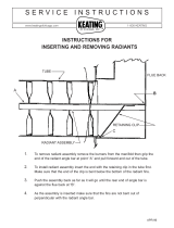
TESTING FOR SPILLAGE
Close all doors and windows to the room containing the appliance. Let the fire run on HIGH for five minutes.
Take a smoke match, light it, and using a smoke match tube, hold it at the top edge of the fire opening, 25mm
down and 25mm in. Starting 50mm in from either side, run the smoke match across the opening. All the smoke
should be drawn into the upper firebox. Any smoke returning into the room indicates that spillage is occurring. If
the initial test fails, run the fire for a further 10 minutes and repeat the test. When the test has been completed
satisfactorily, repeat with any extractor fans in the premises running on the highest setting, and any communicat-
ing doors open. Finally, repeat with all doors open.
NOTE: IIf sspillagge iiss sstill iindiccated aafter uundertakingg aall oof tthe aabove, tthere mmay bbe aa pproblem wwith tthe fflue aand/or
fan bbox ssetup, oor iinssufficcient vventilation iiss ppressent.
If the problem cannot be rectified immediately, then expert advice should be sought. Inform the user, disconnect
the fire, and attach an explanatory label.
BRIEFING TTHE CCUSTOMER
All instructions must be handed to the user for safekeeping.
Show tthe ccusstomer hhow tto lligght aand ccontrol tthe ffire
.
After commissioning the appliance, the customer should be instructed on the safe use of the appliance and the
need for regular servicing. Frequency of service depends on usage, but MUST be carried out at least once
annually.
Scratched and other superficial damage to the matt black paintwork of the appliance can be covered with
matching heatproof spray. Use only the manufacturers’ recommended spray paint. Paint only when the fire is OFF
and cold. Always mask off the surrounding area to prevent contamination with overspray. Ventilate the room
during the use of the spray.
DO NOT attempt to spray paint the coals or ceramics, or wash them in water.
18
11.4
11.5
Match
Crimp
Tube
Cross section of smoke match tube
Make a smoke match tube from 10mm
diameter tube. Seal off one end and crimp
the tube to prevent the smoke match from
sliding down inside.
C
C
B
A
Fireplace Opening
Smoke Match
In Tube
A.25mm down
from top of
opening
B. 25mm in
from front of
opening.
C. Disregard
outer 50mm
either side of
fireplace open-
ing
12.0
/