Page is loading ...

TOP CENTER-MOUNT
BRACKET
T-MOUNT
SIDE RAIL
T-MOUNT
PANEL
BO TTO M
CENTER-MOUNT
BRACKET
T-MOUNT GLIDE
HOUSING
GLIDE STEM
TO P C AP
C O M M U N IC A T IO N
CHANNEL
BASE RACEW AY
ASSEM BLY
1/4 TU R N TO
INSTALL
1/4 TU R N TO
REMOVE
Part No: Rev:
Page:
E.C.O. No: 232-035 1 O F 2 7021-6456 G
CUSTOMER SERVICE PHONE: 1-800-426-8562
FIG . 1
FIG . 2
NOTE:
For ease of installation, identify T-m ounted panel
conditions and install T-m ount kits before joining those
p a n e ls to o th e rs . T -m ount kits m ount on panel side rails
or in pre-drilled holes in panel fram es for center-m ount
conditions. The T-m ount kit can also be m ounted along
the w idth of non-pow ered panels by drilling one 3/8"
d ia m e te r h o le o n e a c h c e n te rlin e o f to p and bottom fram e
ra ils o f th e panel subassem bly (T-m ount kits cannot be
installed w ithin 2½ " of the panel sides due to the length of
the top and bottom fram e rails). O n pow ered panels, T-
m o u n t k its m u s t b e m o u n te d a t le a s t n in e (9 ) in c h e s fro m
the panel side rails to allow receptacle access.
T -M o u n t - C e n te r a n d O ff-C e n te r L o c a tio n
NOTE:
The panel to be T-m ounted to the face of another
panel m ust be of equal height.
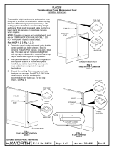
1. R em ove top caps and racew ay covers from panels.
2. R em ove base racew ay assem bly by using a 5/16"
ratchet socket and m aking a quarter-turn to unseat
(F ig . 1 ).
3 . A tta c h to p c e n te r-m o u n t b ra c k e t to T -m o u n t s id e ra il
w ith fo u r (4 ) s c re w s p ro v id e d . In s e rt lig h t b lo c k in to
g ro v e s in T -m o u n t s id e ra il. H o o k to p T -m ount
bracket w ith rail over panel top and into pre-drilled
h o le a t th e b o tto m o f th e 2 " deep com m unication
channel
(F ig . 2 ). T o p c e n te r-m ount bracket m ust be
fully seated onto fram e rail.
4. Insert bottom center-m ount bracket in the pre-drilled
h o le in b o tto m fra m e ra il. A lig n b ra c k e t w ith h o le s in
T-m ount rail and start screw s through rail and into
b ra c k e t. A d ju s t b ra c k e t u p a g a in s t th e p anel fram e
and tighten the screw s
(F ig . 2 ).
5. R eplace base racew ay assem bly
(F ig . 1 ).
6. U nscrew the glide stem and pull the glide housing
from T-m ounted panel, and replace w ith T-m ount
glide housing and glide stem .
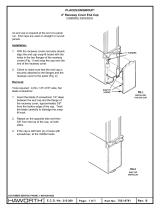
7. N otch racew ay cover retainer flanges to clear bottom
bracket and install.
8. Attach T-m ounted panel to T-m ount rail.
9. C heck that top center m ount is fully seated onto top
ra il.
LIGHT BLOCK
PLACES
®
AND W OOD PLACES
®
T-M OUNT PANEL KIT
In s ta lla tio n In s tru c tio n s
TO P C AP
CLIPS

T-M O UNT PANEL
GLIDE STEM
T-MOUNT
SIDE RAIL
BO TTO M SIDE
RAIL CLIP (TABS
PO INTING UP)
TO P SIDE
RAIL CLIP
T-MOUNT GLIDE
HOUSING
Part No: Rev:
Page:
E.C.O. No: 232-035 2 O F 2 7021-6456 G
CUSTOMER SERVICE PHONE: 1-800-426-8562
FIG . 4
1 0 . T h e e x tra re ta in e r c lip s p ro v id e d m u s t b e in s ta lle d in
the top panel rail, directly adjacent to th e c e n te r
m ount bracket
(F ig . 2 ). M e a s u re fo r p o s itio n o f th e
re ta in e r c lip s in th e to p ra il. A s s e m b le c lip s in to ra il
(F ig . 3 ).
NOTE:
W hen installing w ood top caps , if a T-m ount kit is
installed at a location other than center or end of panel,
the rib on the underside of th e w o o d to p c a p m u s t b e c u t
aw ay to allow the top cap to be properly seated.
1 1 . In s ta ll to p c a p s a c c o rd in g to in s ta lla tio n in s tru c tio n
7021-6452.
T -M o u n t K it - S id e R a il A tta c h m e n t
1 . A tta c h b o tto m s id e ra il c lip to b o tto m o f T -m o u n t ra il.
Tabs should be pointing up on the left o r rig h t s id e o f
T-m ount rail depending on w hich side T-m ount rail is
to b e m o u n te d (F ig . 4 ).
2. R em ove glide stem and glide housing from T-
m ounted panel and replace w ith T-m ount glide
housing and stem .
3. Align top side rail w ith side rail of panel. In s e rt to p
side rail clip into panel side rail.
4. H ook T-m ount side rail into bottom of panel side rail.
A lig n a n d fa s te n T -m o u n t ra il to to p s id e ra il c lip w ith
screw s provided.
5. Attach T-m ounted panel to T-m ount side rail. R e fe r
to S id e R a il A tta c h m e n t In s ta lla tio n In s tru c tio n s .
FIG . 3
PLACE CLIP
ON RAIL AS
SHOW N
ROTATE CLIP UNTIL
IT S N A P S O V E R
TO P SURFACE
/


