Page is loading ...

Model: 41360
Rotary Pump Kit for
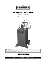
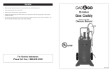
40549/42859 Gas Caddy
REV03/14
OPERATOR’S MANUAL 41360 ROTARY PUMP KIT
4.
Operation
1. Connect the ground wire clamp the container or to a known ground on the vehicle receiving the fuel.
2. Position the dispensing hose in the container or vehicle that is receiving the fuel.
3. Open the ball valve on the gas caddy.
4. Open the vent on the fill cap.
5. Turn the handle clockwise to dispense fuel.
6. Monitor flow and liquid level to prevent spills
To close for storage
1. When finished return remaining fuel back into the tank by laying the tank in the horizontal position, open ball vavle and raise
the hose rotate the pump handle counter-clockwise to allow fuel to return to the tank.
2. Close the ball valve by turning the valve handle until it stops in the 90 ° position.
3. Turn vent until it is closed, then turn an additional 1/8 turn.
4. Return to upright vertical position
Transportation
1. Remove the pump and bracket by loosening the knob and turning the J-hook bracket to release the pump from the gas caddy.
2. Place beside the gas caddy and secure with straps.
Distributed by
Northern Tool + Equipment Co., Inc.
Burnsville, Minnesota 55306
NorthernTool.com
Made in U.S.A.
For replacement parts
and technical questions,
please call
1-800-222-5381.
WARRANTY
1-year limited warranty

OPERATOR’S MANUAL 41360 ROTARY PUMP KIT
INSTRUCTIONS PERTAINING TO THE RISK OR INJURY TO PERSONS.
IMPORTANT SAFETY INSTRUCTIONS. SAVE THESE INSTRUCTIONS.
READ THIS MANUAL CAREFULLY BEFORE INSTALLING,
OPERATING OR SERVICING THIS EQUIPMENT
It is the responsibility of the employer to place this information in the
hands of the operator. Keep for future reference.
• Use caddy for “one type of fuel only” to avoid possible contamination or damage to equipment or motor vehicles.
• Use care when maneuvering to prevent injury or loss of control. Seek assistance to avoid strain or injury when required.
• Mount pump per these instructions only.
• Ground wire must be installed as shown and clamped to the container or to a known ground on the vehicle receiving the
fuel.
• Pump and bracket must be removed from the gas caddy before transportation.
• Return all fuel in hoses and pump into the tank before disconnecting any hoses
•VAPORS CAN EXPLODE
•HARMFUL OR FATAL IF
SWALLOWED
• If swallowed, do not induce vomiting,
call physician immediately.
• Keep out of reach of children.
• Avoid prolonged breathing of vapors.
• Do not siphon by mouth.
• Do not store in vehicle or living space.
• Store and use in well-ventilated area.
• Vapors can be ignited by a spark or flame source many feet
away.
• Keep away from flame, pilot lights, stoves, heaters, electric
motors and other sources of ignition.
• Keep container closed.
• Do not smoke near or while using this gas caddy
ASSEMBLY
Remove original hose and ball valve connection
1. Lay the gas caddy in the horizontal position in a well-ventilated area away from all possible ignition sources.
2. Open the ball valve and return all residual fuel into the tank. Vent the nozzle to allow the fuel to flow. Release the nozzle
and close the ball valve when finished.
3. Remove the original hose and ball valve from the gas caddy by loosening the swivel nut. Use extreme caution as the tank will
be vented to the atmosphere until the hoses are reassembled.
4. Remove the ball valve from the original hose and reassemble to the 1/2” fitting on the 48” hose. Wrap the 1/2” NPT male
threads with PTFE tape. DO NOT USE any PTFE tape or thread sealant on this valve threads.
2.
Required Tools
5 mm hex wrench (included)
#2 Phillips screw driver
10 mm hex wrench
1-1/16 inch open end wrench
1 inch open end wrench
7/8 inch open end wrench
DANGER
WARNING
CAUTION
OPERATOR’S MANUAL 41360 ROTARY PUMP KIT
ASSEMBLY
Pump and bracket assembly instructions
1. Install the handle, large flat washer, Phillips pan head screw and tighten. (See Fig. 1)
2. Use the provided hex wrench and remove the 4 hex head cap screws, flat washers and
lock washers as shown. (See Fig. 2) DO NOT remove the remaining two screws. Install
the two Z brackets and ground wire terminal as shown. Reinstall the cap screws, flat
washers, and lock washers as shown. Tighten securely to assure the pump is sealed.
3. Install the tension tube to the front of the bracket using the hex head cap screw, flat
washer, and flat washer as shown. (See Fig. 3)
4. Mount the pump and brackets to the main bracket using the 4 pan head Phillips screws,
washers, and lock washers as shown. (See Fig. 4)
5. Wrap the the 3/4” NPT male threads on the 48 inch hose with PTFE tape. Thread into the
pump “IN” port and tighten. (See Fig. 5)
6. Assemble the ball valve to the tank 90° swivel fitting. Tighten swivel nut securely to pull
valve against the cone seat. DO NOT use PTFE or pipe sealant on the valve threads.
(See Fig. 6)
Return the gas caddy in the vertical position.
1.Hang the J hook on the gas caddy handle as shown and align the tension tube with the slot. Install the threaded knob and turn the
knob tighten to pull the pump bracket against the handle. (See Fig. 7)
2. Wrap the 3/4” male NPT fitting on the 8 ft. dispensing hose with PTFE tape. Thread the fitting into the rotary pump “OUT” port.
Tighten. (See Fig. 8)
3. Wrap store the 8 ft dispensing hose by wrapping the hose around the tank handle ear as shown in (See Fig. 9)
3.
Fig. 1
Fig. 7 Fig. 8 Fig. 9
Fig. 2
Fig. 3 Fig. 4 Fig. 5 Fig. 6
/


