Page is loading ...

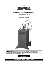
30-Gallon
Gas Caddy
Model No. GG-30GC
Owners Manual
For Service Assistance
Phone Toll Free 1-800-433-0708
1. Attach the green ground wire clamp to a known ground on the vehicle being serviced.
2
. Place the suction/drain hose in the vehicle.
3. Rotate the pump handle briskly to obtain initial prime.
4. Rotate the handle clockwise (as shown by the arrow on the pump) to draw from the gas caddy , rotate counter-
clockwise for suction.
5. The gas caddy may also be filled by removing the fill cap and filling through the fill tube. DO NOT OVERFILL. Fuel
level must be below the flame arrestor screen under the fill tube.
Operation
Rev 10/15
®

Please Read The Following Warnings
Before Assembly and Use of the Gas Caddy
Assembly
WARNING
Gasoline
Danger
Extremely Flammable
Vapors Can Explode
Harmful Or Fatal If Swallowed
Do Not Transport Fuel In Any Vehicle Or Trailer.
Never Fill On/In Motor Vehicle, Truck Or Marine Craft
Vaports Can Cause Flash Fires
Vapors Can Be Ignited By A Spark
WARNING
Keep Away From Flames, Sparks, Pilot Lights, Stoves,
Heaters, Electric Motors Or Other Sources Of Ignition.
Do Not Smoke Near Or While Using Gas Caddy.
Not For Prolonged Storage Of Fuel.
WARNING
Do Not Transport With Pump Attached
Secure Gas Caddy During Transportation
Capacity: 30 U.S. Gallons
Manufactured by and as;
JohnDow Industries, Inc., Barberton, Ohio
Model Number: GG-30GC
WARNING
Do Not Siphon Fuel By Mouth
Avoid Repeated Or Prolonged Contact With Skin
If Swallowed, Do Not Induce Vomiting. Contact Physician Immediately
Avoid Breathing Fuel Vapors
Keep Out Of Reach Of Children
Do Not Overfill Container
Assembly Procedures
1. Remove the gas caddy tank, pump, handle, and accessory kit from the
carton.
2. Remove nylon insert nut, washers, and shoulder bolts from tank. Assemble
handle and reinstall hardware to tank. The shoulder bolt head must be on
the outside of the handle to properly secure the handle. Tighten securely
using 5mm hex wrench and adjustable wrench. (See Fig. 1)
3. Tilt caddy onto its back (handle down) to install the front foot pads. Note the
pads are the same for the left and right foot. (See Fig. 2a)
4. Place on pad on each foot, flipping as required to match the foot bracket.
Install the (2) M6 x 25 mm bolts and tighten with 4mm hex wrench.
(See Fig. 2b)
5. Remove ground screw from tank. Assemble green ground wire to tank by
placing the screw through the connector and threading the screw into the
ground tab on tank. Make certain connection is securely tightened. (See
Fig. 3)
6. Remove all plastic caps from tank and pump. Wrap 3/4” pipe threads with
PTFE tape provided. (See Fig. 4)
7. Install pump on tank with handle facing to outside of tank. (Side makr “IN”
onto 3/4” pipe.) (See Fig. 5)
8. Wrap 3/4” fitting on hose with PTFE tampe and thread onto pump. Tighten
with wrench. (See Fig. 6)
9. Wrap fill tube 2” thread with PTFE tape and thread onto pump. Tighten by
hand until secure Install fill cap. (See Fig. 7)
10. Install plastic dome, plastic nut, and rubber washer onto fuel level gauge.
DO NOT OVER TIGHTEN. If fuel gauge rotates during assembly then
repostition so that the float is free to travel. Verify the correct position by
moving the indicator disk attached to the fuel gauge up and down. (See
Fig. 8)
11. If desired, mount identification label (Unleaded, Gasoline, Diesel, Kerosene
or Transmission Fluid) on the front of the gas caddy.
Fig 1
Tools Required
4mm Hex Wrench
5mm Hex Wrench
A
djustable Wrench
Phillips Screwdriver
PTFE Tape (Included)
Fig 3
Fig 4
Fig 5
Fig 6 Fig 7 Fig 8
Fig 2a
Fig 2b
/