Task Force Tips M-R1250-NN Operating instructions

Type
Operating instructions
©Copyright Task Force Tips LLC 1999-2020 1 LIM-030 November 16, 2020 Rev15
TASK FORCE TIPS LLC
MADE IN USA · tft.com
3701 Innovation Way, Valparaiso, IN 46383-9327 USA
800-348-2686 · 219-462-6161 · Fax 219-464-7155
INSTRUCTIONS FOR INSTALLATION, OPERATION, AND MAINTENANCE
Masterstream
Nozzle Series
WARNING
Understand manual before use. Operation of this device without understanding the manual and
receiving proper training is a misuse of this equipment. Obtain safety information at tft.com/serial-
number.
This equipment is intended for use by trained and qualified emergency services personnel for
firefighting. All personnel using this equipment shall have completed a course of education
approved by the Authority Having Jurisdiction (AHJ).
This instruction manual is intended to familiarize firefighters and maintenance personnel with the
operation, servicing, and safety procedures associated with this product. This manual should be
kept available to all operating and maintenance personnel.
MASTERSTREAM 1000
150 - 1000 GPM @ 100 PSI
600 - 4000 L/min @ 7 BAR (700 kPa)
MASTERSTREAM 1250S
150 - 1250 GPM @ 100 PSI
600 - 4500 L/min @ 7 BAR (700 kPa)
MASTERSTREAM 1250
300 - 1250 GPM @ 70 - 120 PSI
1100 - 4700 L/min @ 4.8 - 8.3 BAR (480 - 830 kPa)
MASTERSTREAM 1500
300 - 1500 GPM @ 70 - 120 PSI
1100 - 5700 L/min @ 4.8 - 8.3 BAR (480 - 830 kPa)
MASTERSTREAM 2000
300 - 2000 GPM @ 80 - 120 PSI
1100 - 7600 L/min @ 5.5 - 8.3 BAR (550 - 830 kPa)
MASTERSTREAM 4000
600 - 4000 GPM @ 80 - 120 PSI
2300 - 15000 L/min @ 5.5 - 8.3 BAR (550 - 830 kPa)
©Copyright Task Force Tips LLC 1999-2020 2 LIM-030 November 16, 2020 Rev15
SUPPORTING MATERIALS
The following documents contain supporting safety and operating
information pertaining to the equipment described in this manual.
LIA-025
Manual: Foam Aspirators
©Copyright Task Force Tips, Inc. 2009 LTT-135 July 28, 2009 Rev00
NOZZLE TRAJECTORY
ELEVATION FACTORS
TASK FORCE TIPS, INC.
MADE IN USA • www.tft.com
3701 Innovation Way, Valparaiso, IN 46383-9327 USA
800-348-2686 • 219-462-6161 • Fax 219-464-7155
1.0 To estimate elevation angle when vertical and horizontal distances to target are known:
1.1 Find the maximum height and reach at 30° from the appropriate trajectory curve in LIM-030 or LIM-035.
1.2 Calculate the Height Factor by dividing the vertical distance to the target by maximum height from step 1.1.
1.3 Calculate the Reach Factor by dividing the horizontal distance to the target by maximum reach from step 1.1.
1.4 On the graph of nozzle trajectory elevation factors, plot the intersection of the Height Factor and Reach factor from steps 1.2 and 1.3. If this point lies
on or between the curves given, estimate the appropriate elevation angle. If this point lies within the shaded region of the graph, then a higher ÀRZ or
pressure must be used to reach the target.
2.0 To estimate maximum reach for a given elevation angle above 0°:
2.1 From the graph of nozzle trajectory elevation factors, choose the trajectory curve for the desired elevation angle.
2.2 Find the point where this trajectory curve intersects the height of discharge (zero height line).
2.3 Estimate the Reach Factor at this point using the scale across the top of the graph.
2.4 Multiply this Reach Factor by the reach at 30° elevation from the appropriate trajectory curve in LIM-030 or LIM-035.
3.0 To estimate maximum height for a given elevation angle above 0°:
3.1 From the graph of nozzle trajectory elevation factors, choose the trajectory curve for the desired elevation angle.
3.2 Find the maximum height on this trajectory curve.
3.3 Estimate the Height Factor at the maximum height using the scale on the left side of the graph.
3.4 Multiply this Height Factor by the height at 30° elevation from the appropriate trajectory curve in LIM-030 or LIM-035.
Stream reach and height at non-optimal elevations can be estimated as a factor of the performance at the optimal 30° elevation.
Refer to LIM-030 and LIM-035 for effective stream trajectories of Task Force Tips Masterstream nozzles at 30° elevation.
This graph cannot be used to estimate maximum reach for elevation angles below 30°.
-
-45
°-
-30°
--
15
°-
0
°
15°
30°
45°
60°
75°
85°
-2.0
-1.5
-1.0
-0.5
0.0
0.5
1.0
1.5
2.0
2.5
3.0
3.5
0.0 0.1 0.2 0.3 0.4 0.5 0.6 0.7 0.8 0.9 1.0 1.
1
Reach Factor (compared to 30° elevation)
Height Factor (compared to 30° elevation)
height of
discharge
IF TARGET IS IN THIS REGION,
FLOW AND/OR PRESSURE MUST
BE INCREASED.
TASK FORCE TIPS
ELECTRIC REMOTE NOZZLES
ELECTRIC REMOTE WIRING DIAGRAM
TASK FORCE TIPS LLC 3701 INNOVATION WAY, VALPARAISO, IN 46383-9327
(800) 348-2686 (219) 462-6161 FAX (219) 464-7155
MADE IN USA • TFT.COM
LESS ELABORATE WIRING
SYSTEMS MAY BE USED BY
ELIMINATING UPPER CONTROL
OR REMOTE CONTROL STATIONS
LIM-040 August 1, 2018 Rev05©Copyright Task Force Tips LLC 1998-2018
LIM-040
ER Nozzle Wiring Guide
©Copyright Task Force Tips LLC 2008-2019 LIY-500 April 8, 2019 Rev14
MANUAL: Remote Control (RC)
Monitor Electrical Controls
Supplemental Instructions for use with RC Monitor Manual
INSTRUCTIONS FOR INSTALLATION, SAFE OPERATION AND MAINTENANCE
DANGER
Understand manual before use. Operation of this device without understanding the manual and
receiving proper training is a misuse of this equipment. Obtain safety information at www.tft.
com/serial-number
TASK FORCE TIPS LLC
MADE IN USA • tft.com
3701 Innovation Way, IN 46383-9327 USA
800-348-2686 • 219-462-6161 • Fax 219-464-7155
SECTION 4.1
Monitor Mounted
Operator Station
SECTION 4.2
Panel Mount
Operator Station
(Y4E-RP)
SECTION 4.3
Panel Mount With Display
Operator Station
(Y4E-RP-D)
SECTION 4.4
Tethered
Operator Station
(Y4E-CT-##)
SECTION 4.5
Tethered Operator Station
With Display
(Y4E-CT-##-D)
SECTION 4.6
Wireless
Operator Station
(YE-RF-##)
SECTION 4.7
Wireless Operator Station
With Display
(YE-RF-##-D)
SECTION 3.0
SECTION 4.0
Electrical Controls Installation and Operation
SECTION 4.11
Monitor Position Display
(Y4E-DISP)
SECTION 4.12
Remote Auxiliary Function
Interface Control
(YE-REMAUX)
SECTION 4.13
Electric RC Monitor Aerial
Truck Installation
SECTION 4.16
Electric Nozzle Actuator
SECTION 4.17
Valve Kits
(YE-VK-PH)
SECTION 5.0
Troubleshooting
SECTION 4.14
Multiplex Interface Control (YE-CAN#)
SECTION 4.15
Ethernet Interface Control
SECTION 4.9
Toggle Switch Monitor
Operator Station
(Y4E-TS)
SECTION 4.10
Monitor Communication
Interface Control
(Y4E-COMM)
SECTION 4.8
Joystick
Operator Station
(Y4E-JS)
LIY-500
Manual: Remote Control (RC)
Monitor Electrical Controls
LTT-135
Nozzle Trajectory Elevation
Factors
©Copyright Task Force Tips LLC 1999-2020 3 LIM-030 November 16, 2020 Rev15
TABLE OF CONTENTS
1.0 MEANING OF SAFETY SIGNAL WORDS
2.0 SAFETY
3.0 GENERAL INFORMATION
3.1 VARIOUS MODELS AND TERMS
3.2 SPECIFICATIONS
3.3 NOZZLE COUPLINGS
3.4 USE WITH SALT WATER
3.5 HYDRAULIC INSTALLATION
3.6 ELECTRIC INSTALLATION
4.0 FLOW CHARACTERISTICS
4.1 MASTERSTREAM 1000 & 1250S (AUTOMATIC)
4.2 MASTERSTREAM 1250, 1500, 2000, & 4000 (AUTOMATIC)
4.3 MASTERSTREAM 1000 (SELECTABLE)
4.4 MASTERSTREAM 1000 (FIXED)
4.5 REACH AND TRAJECTORY
5.0 OPERATION
5.1 PATTERN CONTROL
5.2 FLUSHING DEBRIS
6.0 USE WITH FOAM
6.0.1 FOAMJET LX WITH MASTERSTREAM 1000 AND 1250S NOZZLE
7.0 WARRANTY
8.0 MAINTENANCE
8.1 FIELD LUBRICATION
8.2 SERVICE TESTING
8.3 REPAIR
9.0 EXPLODED VIEWS AND PARTS LISTS
10.0 OPERATION AND INSPECTION CHECKLIST
The member companies of FEMSA that provide emergency
response equipment and services want responders to know and
understand the following:
1. Firefighting and Emergency Response are inherently
dangerous activities requiring proper training in their hazards
and the use of extreme caution at all times.
2. IT IS YOUR RESPONSIBILITY to read and understand
any user’s instructions, including purpose and limitations,
provided with any piece of equipment you may be called on
to use.
3. IT IS YOUR RESPONSIBILITY to know that you have been
properly trained in Firefighting and/or Emergency Response
and in the use, precautions, and care of any equipment you
may be called upon to use.
4. IT IS YOUR RESPONSIBILITY to be in proper physical
condition and to maintain the personal skill level required to
operate any equipment you may be called upon to use.
5. IT IS YOUR RESPONSIBILITY to know that your equipment is
in operable condition and has been maintained in accordance
with the manufacturer’s instructions.
6. Failure to follow these guidelines may result in death, burns or
other severe injury.
Fire and Emergency Manufacturers and Service Association, Inc.
PO Box 147, Lynnfield, MA 01940 • www.FEMSA.org
DANGER
PERSONAL RESPONSIBILITY CODE
©Copyright Task Force Tips LLC 1999-2020 4 LIM-030 November 16, 2020 Rev15
1.0 MEANING OF SAFETY SIGNAL WORDS
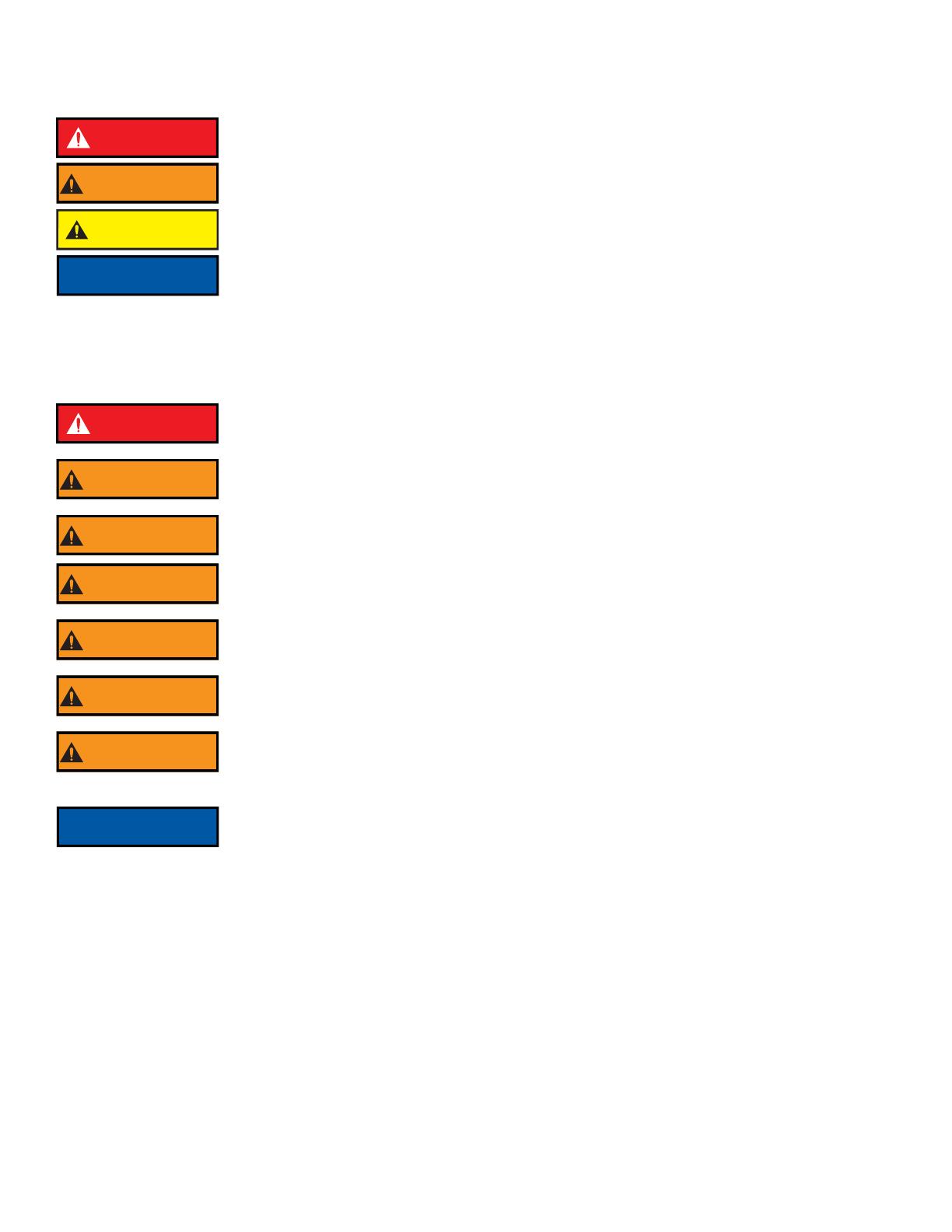
A safety related message is identified by a safety alert symbol and a signal word to indicate the level of risk involved with a particular
hazard. Per ANSI Z535.6, the definitions of the four signal words are as follows:
2.0 SAFETY
OPERATING NOTE ABOUT AUTOMATIC NOZZLES: The automatic nozzle is considerably different than Fixed and Selectable Flow
nozzles because of basic changes in the operating principle. These differences not only assure the most effective operation under a
variety of conditions, but will also utilize the available water supply most efficiently. It is important that nozzle operators, pump operators,
and officers be fully aware of these differences. Therefore, proper instruction is required for safe and effective operations.
DANGER
DANGER indicates a hazardous situation which, if not avoided, will result in death or serious injury.
WARNING
WARNING indicates a hazardous situation which, if not avoided, could result in death or serious
injury.
CAUTION CAUTION indicates a potentially hazardous situation which, if not avoided, could result in minor
or moderate injury.
NOTICE
NOTICE is used to address practices not related to physical injury.
DANGER
An inadequate supply of pressure and/or flow will cause an ineffective stream and can result
in injury or death. Choose operating conditions to deliver adequate fire suppression. See flow
graphs.
WARNING
This equipment is intended for use by trained personnel for firefighting. Use of this equipment for
other purposes may involve hazards not addressed by this manual. Seek appropriate guidance and
training to reduce risk of injury.
WARNING
Injury or damage can occur from an inadequately supported monitor. The mounting must be
capable of supporting the nozzle reaction force which can be as high as 1500 lbs.
WARNING
Some volatile liquids can be ignited by static discharge, which can occur during application of foam
or water. Fire or explosion can result in injury or death. Follow procedures established by the AHJ
to reduce risk of fire or explosion caused by static discharge.
WARNING
Application of water or foam solutions on energized electrical equipment could cause
electrocution. Serious injury or death could result. Assume circuits are energized until confirmed to
be de-energized. Do not apply water or foam to energized electrical equipment.
WARNING
The stream exiting a nozzle is very powerful and capable of causing injury and property damage.
Make sure the nozzle is securely attached and pointing in a safe direction before water is turned on.
Do not direct water stream to cause injury or damage to persons or property.
WARNING
Equipment may be damaged if frozen while containing significant amounts of water. Such damage
may be difficult to detect visually. Subsequent pressurization can lead to injury or death. Any time
the equipment is subject to possible damage due to freezing, it must be tested and approved for
use by qualified personnel before being considered safe for use.
NOTICE
To prevent mechanical damage, do not drop or throw equipment.
©Copyright Task Force Tips LLC 1999-2020 5 LIM-030 November 16, 2020 Rev15
3.0 GENERAL INFORMATION
The Task Force Tips Masterstream Series nozzles are deluge nozzles with clean, far reaching straight stream capability. They are
adjustable from straight stream to a dense fog pattern.
The Task Force Tips Masterstream Series Nozzles automatic nozzles operate by sensing the pressure at the nozzle inlet and adjusting
the discharge opening to maintain a constant pressure throughout the flow range of the nozzle. While flowing, the stream pattern can be
varied from wide fog to straight stream. Trapped debris can be removed without the use of tools.
3.1 VARIOUS MODELS AND TERMS
NOTES ON ABOVE TABLE
Other threads, coupling sizes, or connector styles can be specified at time of order.
Masterstream 1250, 1500, 2000, and 4000 nozzles are field adjustable within the range of pressures shown.
For long term installations, it is recommended that the threads be greased before installing the nozzle.
AUTOMATIC SERIES FLOW RANGE NOMINAL PRESSURE STANDARD COUPLING
GPM L/min PSI BAR, kPa/
100
MASTERSTREAM 1000 150-1000 600-4000 100 7 2.5” NH FEMALE
MASTERSTREAM 1250S 150-1250 600-4500 100 7 2.5” NH FEMALE
MASTERSTREAM 1250 300-1250 1100-4700 70-120 4.8-8.3 2.5” NH FEMALE or
3.5” NH FEMALE
MASTERSTREAM 1500 300-1500 1100-5700 70-120 4.8-8.3 2.5” NH FEMALE or
3.5” NH FEMALE
MASTERSTREAM 2000 300-2000 1100-7600 80-120 5.5-8.3 3.5” NH FEMALE
MASTERSTREAM 4000 600-4000 2350-15000 80-120 5.5-8.3 6.0” ANSI 150 FLANGE
FIXED/SELECTABLE
SERIES
FLOW PRESSURE K
FACTOR
STANDARD
COUPLING
GPM L/min PSI BAR, kPa/100
MASTERSTREAM
1000 FIXED
CUSTOMER
SPECIFIED
1000 GPM MAX
CUSTOMER
SPECIFIED
4000 L/min MAX
CUSTOMER
SPECIFIED
150 PSI MAX
CUSTOMER
SPECIFIED
10 BAR MAX
50-100 2.5" NH
FEMALE
MASTERSTREAM
1000 SELECTABLE
250, 350, 500,
750, 1000
1000, 1500,
2000, 3000, 4000
100 7 15-75 2.5" NH
FEMALE
MASTERSTREAM
1250 SELECTABLE
300, 500, 700,
1000, 1250
1200, 1800,
2400, 3600, 4800
150 10 50-105 2.5" NH
FEMALE
©Copyright Task Force Tips LLC 1999-2020 6 LIM-030 November 16, 2020 Rev15
3.1 VARIOUS MODELS AND TERMS (CONTINUED)
The spray pattern is changed from wide fog to straight stream by means of the “stream shaper”. Models are available with six different
methods to move the stream shaper as shown.
Figure 3.1A
Figure 3.1B
Figure 3.1C
Coupling
Halo Ring
Stream Shaper/
Bumper
Stream Shaper moved manually
by rotating the Halo Ring or Bumper
Serial
Number
Manual Override Knob
(Masterstream 1000,
1250, 1500, and 2000 Only)
Stream Shaper moved
remotely by electricity (12-24 volts)
Serial Number
©Copyright Task Force Tips LLC 1999-2020 7 LIM-030 November 16, 2020 Rev15
3.2 SPECIFICATIONS
Table 3.2
3.3 NOZZLE COUPLINGS
NH (National Hose Threads) threads are standard on all nozzles. Other threads such as NPSH (National Pipe Straight Hose) may be
specified at time of order.
3.4 USE WITH SALT WATER
Use with salt water is permissible provided the equipment is thoroughly cleaned with fresh water after each use. The service life of the
equipment may be shortened due to the effects of corrosion, and is not covered under warranty.
3.5 HYDRAULIC INSTALLATION
On nozzles with hydraulic stream shaper actuation, the hydraulic system is connected to the nozzle with two 1/8”-27 NPT female ports
on the filter block located on the nozzle’s stream shaper. When the port on the left of the filter block (as seen from behind the nozzle) is
pressurized, the shaper moves back into the wide fog position. Pressurizing the right port moves the shaper forward into straight stream.
Hydraulic lines must be flexible to allow for movement of the stream shaper. Use only clean fluid compatible with Buna N Compound
(Nitrile). System must be free from all dirt, chips and contaminants. Replacement filter elements are available from TFT (item #M160).
Maximum hydraulic pressure is 1000 psi (70 bar, 7000 kPa) for Masterstream 1000 or 1250s.
3.6 ELECTRIC INSTALLATION
Nozzles with electric stream shaper actuation are shipped with a wiring diagram (TFT item #LIM-040). Other documentation is available
on request. ER nozzles are equipped with manual override in case of electrical power failure.
US METRIC
Operating temperature of fluid 33 to 120°F 1 to 50°C
Storage temperature range -40 to 150°F -40 to 65°C
Materials used Aluminum 6000 series hard anodized MIL 8625 class 3 type
2, stainless steel 300 series, nylon 6-6, nitrile rubber
CAUTION Mismatched or damaged waterway connections may cause equipment to leak or uncouple under
pressure. Failure could result in injury. Equipment must be mated to matched connections.
CAUTION Dissimilar metals coupled together can cause galvanic corrosion that can result in the inability to
uncouple the connection, or complete loss of engagement over time. Failure could cause injury. Per
NFPA 1962, if dissimilar metals are left coupled together, an anti-corrosive lubricant should be
applied to the connection and the coupling should be disconnected and inspected at least
quarterly.
WARNING
This device is not rated as ignition proof, explosion proof, or intrinsically safe. Use only in locations
with adequate ventilation and no hazard of flammable vapor buildup.
©Copyright Task Force Tips LLC 1999-2020 8 LIM-030 November 16, 2020 Rev15
4.0 FLOW CHARACTERISTICS
4.1 MASTERSTREAM 1000 & 1250S (AUTOMATIC)
Within its flow range, the Masterstream 1000 and 1250s automatic nozzles operate at the nominal pressure of 100 PSI (7 BAR, 700 kPa).
The following figures show typical performance of this nozzle.
Figure 4.1A
Figure 4.1B
MASTERSTREAM 1000 PERFORMANCE
0
20
40
60
80
100
120
140
160
0 200 400 600 800 1000 1200 1400 1600 1800 2000
FLOW (GPM)
PRESSURE (PSI)
0
2
4
6
8
10
0 1000 2000 3000 4000 5000 6000 7000
FLOW (L/MIN)
PRESSURE (BAR, KPA/100)
FLOW RANGE
©Copyright Task Force Tips LLC 1999-2020 9 LIM-030 November 16, 2020 Rev15
4.2 MASTERSTREAM 1250, 1500, 2000, & 4000 (AUTOMATIC)
The operating pressure of these nozzles is user adjustable. Pressure adjustment is performed by twisting a knob on the front of the
nozzle to the desired pressure setting. The following figures show typical flow performance for each model when adjusted to marked
pressure settings. The automatic pressure control will maintain the set pressure anywhere within the flow ranges shown on the graphs,
which vary according to pressure setting.
Figure 4.2A
Figure 4.2B
Figure 4.2C
MASTERSTREAM 1250 PERFORMANCE
0
20
40
60
80
100
120
140
160
0 200 400 600 800 1000 1200 1400 1600 1800 2000
FLOW (GPM)
PRESSURE (PSI)
0
2
4
6
8
10
0 1000 2000 3000 4000 5000 6000 7000
FLOW (L/MIN)
PRESSURE (BAR, KPA/100)
FLOW RANGE
110 PSI SETTING
100 PSI SETTING
90 PSI SETTING
80 PSI SETTING
70 PSI SETTING
120 PSI SETTING 8 BAR
7 BAR
6 BAR
5 BAR
To adjust the Master 1250 and
1500, simply twist the pressure
adjustment knob to the desired
detent setting.
MASTERSTREAM 1500 PERFORMANCE
0
20
40
60
80
100
120
140
160
0 200 400 600 800 1000 1200 1400 1600 1800 2000
FLOW (GPM)
PRESSURE (PSI)
0
2
4
6
8
10
0 1000 2000 3000 4000 5000 6000 7000
FLOW (L/MIN)
PRESSURE (BAR, KPA/100)
FLOW RANGE
110 PSI SETTING
100 PSI SETTING
90 PSI SETTING
80 PSI SETTING
70 PSI SETTING
120 PSI SETTING 8 BAR
7 BAR
6 BAR
5 BAR
©Copyright Task Force Tips LLC 1999-2020 10 LIM-030 November 16, 2020 Rev15
Figure 4.2D
Figure 4.2E
Figure 4.2F
©Copyright Task Force Tips LLC 1999-2020 11 LIM-030 November 16, 2020 Rev15
4.3 MASTERSTREAM 1000 (SELECTABLE)
The Masterstream 1000 Selectable Nozzle allows the user to select one of several orifice sizes by turning a knob at the front of the
nozzle. An indicator on the knob shows which flow has been selected. The figure below gives relationship of flow and pressure for
various orifice size.
Figure 4.3
4.4 MASTERSTREAM 1000 (FIXED)
The Masterstream 1000 Fixed Flow Nozzle is set to the desired flow by adjusting the baffle and locking it in place with a jam nut. The
nozzle is adjusted and flow tested at the factory at time of order. If the baffle is moved (for example to flush the nozzle), then the baffle
must be readjusted to obtain the desired flow. Refer to Figure 3.2 for baffle position to achieve a certain flow and pressure. The figure
below gives relationship of flow and pressure for various orifice sizes.
Figure 4.4
©Copyright Task Force Tips LLC 1999-2020 12 LIM-030 November 16, 2020 Rev15
4.5 REACH AND TRAJECTORY
Notes on trajectory graphs:
Graphs show approximate effective stream trajectory at 30 degrees elevation in no wind conditions. Distance to last water drops
approximately 10% farther.
To estimate trajectories at elevations other than 30 degrees, refer to document LTT-135, available at tft.com.
Trajectories shown are for water. The addition of foam is expected to decrease the reach by 10%.
Tail or head winds of 20 MPH (30 KPH) may increase or decrease the range approximately 30%.
Figure 4.5A
Figure 4.5B
CAUTION Dents or nicks in the nozzle tip can seriously affect the stream reach or pattern, which may increase
the risk of injury due to exposure. Care must be taken to avoid dents or nicks in the nozzle tip.
0 0
10
10
20
20
30
40
50
60
70
80
0
0
20
10
40
20
60
30
80
40
100
50
120
60
140
70
160
80 90
180 200 220 240 260 280 300
HORIZONTAL DISTANCE (FEET)
VERTICAL DISTANCE (FEET)
METERS
METERS
A
B
C
D
E
MASTERSTREAM 1000/1250s, 100 PSI (7 BAR, 700 KPA )
CURVE
A
B
C
D
E
GPM
FLOW
300
400
500
800
1000
LBS
REACTION
150
200
260
400
510
CURVE
A
B
C
D
E
LPM
FLOW
1100
1500
1900
3000
3800
KGF
REACTION
70
90
120
180
230
GPM
LBS
CURVE FLOW
REACTION
A300
130
B500
210
C800 340
D1000 420
E1250 530
LPM
KGF
CURVE
FLOW
REACTION
A
1100
60
B
1900
100
C3000 150
D3800 190
E4700 240
0
10
20
30
40
50
60
70
80
0 20 40 60 80 100 120 140 160 180 200 220 240 260 280 300
HORIZONTAL DISTANCE (FEET)
VERTICAL DISTANCE (FEET)
0
5
10
15
20
0 102030405060708090
METERS
METERS
MASTERSTREAM 1250, 70 PSI (4.8 BAR, 480 KPA)
ABC
D
E
©Copyright Task Force Tips LLC 1999-2020 13 LIM-030 November 16, 2020 Rev15
Figure 4.5C
Figure 4.5D
Figure 4.5E
0
10
20
30
40
50
60
70
80
0 20 40 60 80 100 120 140 160 180 200 220 240 260 280 300
HORIZONTAL DISTANCE (FEET)
VERTICAL DISTANCE (FEET)
0
5
10
15
20
0 102030405060708090
METERS
METERS
MASTERSTREAM 1250, 100 PSI (7 BAR, 700 KPA)
ABC
D
E
GPM
LBS
CURVE FLOW
REACTION
A300
150
B500 250
C800 400
D1000 510
E1250 630
LPM
KGF
CURVE
FLOW REACTION
A
1100
70
B
1900
120
C3000 180
D3800 230
E4700 290
0
10
20
30
40
50
60
70
80
0 20 40 60 80 100 120 140 160 180 200 220 240 260 280 300
HORIZONTAL DISTANCE (FEET)
VERTICAL DISTANCE (FEET)
0
5
10
15
20
0 102030405060708090
METERS
METERS
MASTERSTREAM 1250, 120 PSI (8.3 BAR, 830 KPA)
ABC
D
E
GPM
LBS
CURVE FLOW
REACTION
A300
170
B500 280
C800 440
D1000 550
E1250 690
LPM
KGF
CURVE
FLOW
REACTION
A
1100
70
B1900 130
C3000 200
D3800 250
E4700 310
0
10
20
30
40
50
60
70
80
0 20 40 60 80 100120140160180200220240260280300
HORIZONTAL DISTANCE (FEET)
VERTICAL DISTANCE (FEET)
0
5
10
15
20
0102030405060708090
METERS
METERS
MASTERSTREAM 1500, 70 PSI (4.8 BAR, 48 KPA)
ABC
D
E
GPM
LBS
LPM
KGF
CURVE
FLOW
REACTION
CURVE
FLOW
REACTION
A
300
130
A
1100
60
B600
250
B
2300
120
C1000 420 C3800 190
D1250 530 D4700 240
E1500 630 E5700 290
©Copyright Task Force Tips LLC 1999-2020 14 LIM-030 November 16, 2020 Rev15
Figure 4.5F
Figure 4.5G
Figure 4.5H
0
10
20
30
40
50
60
70
80
0 20 40 60 80 100 120 140 160 180 200 220 240 260 280 300
HORIZONTAL DISTANCE (FEET)
VERTICAL DISTANCE (FEET)
0
5
10
15
20
0 102030405060708090
METERS
METERS
MASTERSTREAM 2000, 80 PSI (5.5 BAR, 55 KPA)
ABC
D
E
GPM
LBS
LPM
KGF
CURVE FLOW
REACTION
CURVE
FLOW
REACTION
A300
140
A
1100
60
B600
270
B
2300
120
C1000 450 C3800 200
D1500 680 D5700 310
E2000 900 E7500 400
©Copyright Task Force Tips LLC 1999-2020 15 LIM-030 November 16, 2020 Rev15
Figure 4.5I
Figure 4.5J
Figure 4.5K
0
10
20
30
40
50
60
70
80
0 20 40 60 80 100 120 140 160 180 200 220 240 260 280 300
HORIZONTAL DISTANCE (FEET)
VERTICAL DISTANCE (FEET)
0
5
10
15
20
0 102030405060708090
METERS
METERS
MASTERSTREAM 2000, 100 PSI (7 BAR, 700 KPA)
ABC
D
E
GPM
LBS
LPM
KGF
CURVE FLOW
REACTION
CURVE
FLOW
REACTION
A300
150
A
1100
70
B600
300
B
2300
140
C1000 510 C3800 230
D1500 760 D5700 350
E2000 1010 E7500 460
0
10
20
30
40
50
60
70
80
0 20 40 60 80 100120140160180200220240260280300
HORIZONTAL DISTANCE (FEET)
VERTICAL DISTANCE (FEET)
0
5
10
15
20
0 102030405060708090
METERS
METERS
MASTERSTREAM 2000, 120 PSI (8.3 BAR, 830 KPA)
ABC
D
E
GPM
LBS
LPM
KGF
CURVE FLOW
REACTION
CURVE
FLOW
REACTION
A300
170
A
1100
70
B600
330
B
2300
150
C1000 550 C3800 250
D1500 830 D5700 380
E2000 1110 E7500 500
CURVE
A
B
C
D
E
GPM
FLOW
600
1000
2000
3000
4000
LBS
REACTION
280
470
950
1400
1900
CURVE
A
B
C
D
E
LPM
FLOW
2300
3800
7600
11000
15000
KGF
REACTION
130
210
430
640
860
0
10
20
30
60 80 100 120
160 200 240 280 320 360 400
HORIZONTAL DISTANCE (FEET)
METERS
METERS
B
C
D
E
0
20
40
60
80
100
0
020
40
40
80 120
VERTICAL DISTANCE (FEET)
A
MASTERSTREAM 4000, 80 PSI (5.5 BAR, 550 KPA)
©Copyright Task Force Tips LLC 1999-2020 16 LIM-030 November 16, 2020 Rev15
Figure 4.5L
Figure 4.5M
CURVE
A
B
C
D
E
GPM
FLOW
600
1000
2000
3000
4000
LBS
REACTION
320
530
1100
1600
2100
CURVE
A
B
C
D
E
LPM
FLOW
2300
3800
7600
11000
15000
KGF
REACTION
150
240
500
730
950
VERTICAL DISTANCE (FEET)
0
10
20
30
METERS
02040 80
METERS
60 100 120
0
20
40
60
80
100
0 40 80 120 160 200 240 280 320 360 400
HORIZONTAL DISTANCE (FEET)
A
B
C
D
E
MASTERSTREAM 4000, 100 PSI (7 BAR, 700 KPA)
CURVE
A
B
C
D
E
GPM
FLOW
600
1000
2000
3000
4000
LBS
REACTION
350
580
1200
1700
2300
CURVE
A
B
C
D
E
LPM
FLOW
2300
3800
7600
11000
15000
KGF
REACTION
160
260
550
770
1000
VERTICAL DISTANCE (FEET)
0
10
20
30
METERS
02040 80
METERS
0
10
20
30
40
50
60
70
80
90
100
0 40 80 120 160 200 240 280 320 360 400
HORIZONTAL DISTANCE (FEET)
A
B
C
D
E
MASTERSTREAM 4000, 120 PSI (8.3 BAR, 830 KPA)
60 100 120
©Copyright Task Force Tips LLC 1999-2020 17 LIM-030 November 16, 2020 Rev15
5.0 OPERATION
5.1 PATTERN CONTROL
TFT’s Masterstream with Flush Series nozzles have full pattern control from straight stream to wide fog.
On models with manual shapers, turning the stream shaper clockwise (as seen from the operating position behind the nozzle) moves the
shaper to the straight stream position.
On ER models, press and hold the FOG or STRAIGHT STREAM button until the desired pattern is obtained.
Since the stream trim point varies with flow, the nozzle should be “trimmed” after changing the flow to obtain the straightest and farthest
reaching stream. To properly trim a stream, first open the pattern to narrow fog. Then close the stream to parallel to give maximum
reach. Note: Turning the shaper further forward will cause stream crossover and reduce the effective reach of the nozzle.
5.2 FLUSHING DEBRIS
Debris in the water may get caught inside the nozzle. This trapped material will cause poor stream quality, shortened reach and reduced
flow. To remove debris trapped in the nozzle:
1. Shut off flow to the nozzle.
2. Move the stream shaper to the wide fog position.
For Selectable Nozzles: Turn flow selector on front to “FLUSH” position.
For Fixed Nozzles: Remove nozzle to gain access.
For Automatic Nozzles: Carefully unscrew and remove the piston/cylinder.
Notes for 1000 and 1250s Nozzles:
The cylinder is under about 25 lbs (11Kgf) of spring force. The spring must be compressed to reinstall.
A long white push rod is part of the cylinder assembly. Pull cylinder straight out until push rod clears shaft.
Notes for 1250, 1500, 2000 and 4000 Nozzles:
Remove the piston, return spring and cylinder.
Remove the small spring and stainless steel poppet from the center of the shaft as a unit.
3. Remove/flush debris. Flow water if necessary.
4. Reassemble the nozzle.
The following figures show the pieces that are removed during the flush procedure of the various Automatic nozzles.
Figure 5.2A
WARNING
Large amounts or pieces of debris may be unflushable and can reduce the flow of the nozzle
resulting in an ineffective flow. In the event of a blockage, it may be necessary to retreat to a safe
area, uncouple the nozzle and remove debris.
RETURN SPRING
CYLINDER
PUSH RODPISTON
SHAFT
MASTERSTREAM 1000 AND 1250S FRONT END PARTS
©Copyright Task Force Tips LLC 1999-2020 18 LIM-030 November 16, 2020 Rev15
Figure 5.2B
Figure 5.2C
Figure 5.2D
CONTROL
SPRING
SHAFT
POPPET
CYLINDER
RETURN
SPRING
PISTON
MASTERSTREAM 1250 AND 1500 FRONT END PARTS
RETURN
SPRING
CYLINDER
SHAFT POPPET CONTROL
SPRING
PISTON
MASTERSTREAM 2000 FRONT END PARTS
SHAFT
POPPET
CONTROL
SPRING
CYLINDER PISTON
RETURN
SPRING
MASTERSTREAM 4000 FRONT END PARTS
©Copyright Task Force Tips LLC 1999-2020 19 LIM-030 November 16, 2020 Rev15
6.0 USE WITH FOAM
The nozzle may be used with foam solutions. Refer to fire service training by the Authority Having Jurisdiction (AHJ) for the proper use
of foam.
6.0.1 FOAMJET LX WITH MASTERSTREAM 1000 AND 1250S NOZZLE
To increase the expansion ratio, Task Force Tips Foamjet LX” (model FJ-LX-M) may be used with the Masterstream 1000 and 1250s
nozzles. This low expansion foam tube attaches and detaches quickly from the nozzle. Adjust nozzle spray pattern to give best foam
quality. Note: As expansion ratio is increased, the reach of the nozzle will be decreased due to the greater amount of bubbles in the
stream and their inability to penetrate the air. The reach with foam is approximately 10% less than with water only. Actual results will vary
based on brand of foam, hardness of water, temperature, etc.
Figure 6.0.1
WARNING
For Class B fires, lack of foam or interruption in the foam stream can cause a break in the foam
blanket and greatly increase the risk of injury or death. Follow procedures established by the AHJ
for the specific fuel and conditions.
WARNING
Improper use of foam or using the wrong type of foam can result in illness, injury, or damage to the
environment. Follow foam manufacturer’s instructions and fire service training as directed by the
AHJ.
©Copyright Task Force Tips LLC 1999-2020 20 LIM-030 November 16, 2020 Rev15
7.0 WARRANTY
Task Force Tips LLC, 3701 Innovation Way, Valparaiso, Indiana 46383-9327 USA (“TFT”) warrants to the original purchaser of its
products (“equipment”), and to anyone to whom it is transferred, that the equipment shall be free from defects in material and
workmanship during the five (5) year period from the date of purchase. TFT’s obligation under this warranty is specifically limited to
replacing or repairing the equipment (or its parts) which are shown by TFT’s examination to be in a defective condition attributable to
TFT. To qualify for this limited warranty, the claimant must return the equipment to TFT, at 3701 Innovation Way, Valparaiso, Indiana
46383-9327 USA, within a reasonable time after discovery of the defect. TFT will examine the equipment. If TFT determines that there is
a defect attributable to it, TFT will correct the problem within a reasonable time. If the equipment is covered by this limited warranty, TFT
will assume the expenses of repair.
If any defect attributable to TFT under this limited warranty cannot be reasonably cured by repair or replacement, TFT may elect to
refund the purchase price of the equipment, less reasonable depreciation, in complete discharge of its obligations under this limited
warranty. If TFT makes this election, claimant shall return the equipment to TFT free and clear of any liens and encumbrances.
This is a limited warranty. The original purchaser of the equipment, any person to whom it is transferred, and any person who is an
intended or unintended beneficiary of the equipment, shall not be entitled to recover from TFT any consequential or incidental damages
for injury to person and/or property resulting from any defective equipment manufactured or assembled by TFT.
It is agreed and understood that the price stated for the equipment is in part consideration for limiting TFT’s liability. Some states do not
allow the exclusion or limitation of incidental or consequential damages, so the above may not apply to you.
TFT shall have no obligation under this limited warranty if the equipment is, or has been, misused or neglected (including failure to
provide reasonable maintenance) or if there have been accidents to the equipment or if it has been repaired or altered by someone else.
THIS IS A LIMITED EXPRESS WARRANTY ONLY. TFT EXPRESSLY DISCLAIMS WITH RESPECT TO THE EQUIPMENT ALL
IMPLIED WARRANTIES OF MERCHANTABILITY AND ALL IMPLIED WARRANTIES OF FITNESS FOR A PARTICULAR PURPOSE.
THERE IS NO WARRANTY OF ANY NATURE MADE BY TFT BEYOND THAT STATED IN THIS DOCUMENT.
This limited warranty gives you specific legal rights, and you may also have other rights which vary from state to state.
  • Page 1 1
  • Page 2 2
  • Page 3 3
  • Page 4 4
  • Page 5 5
  • Page 6 6
  • Page 7 7
  • Page 8 8
  • Page 9 9
  • Page 10 10
  • Page 11 11
  • Page 12 12
  • Page 13 13
  • Page 14 14
  • Page 15 15
  • Page 16 16
  • Page 17 17
  • Page 18 18
  • Page 19 19
  • Page 20 20
  • Page 21 21
  • Page 22 22
  • Page 23 23
  • Page 24 24

Task Force Tips M-R1250-NN Operating instructions

Type
Operating instructions

Ask a question and I''ll find the answer in the document

Finding information in a document is now easier with AI