Page is loading ...

Questions? Email us: support@cleanwaterstore.com or 831-462-8500 Page 1 | 24 Rev 052219
9510 Sediment Backwash Filter Installation &
Maintenance Guide
Thank you for purchasing a Clean Water System!
With proper installation and a little routine maintenance your system
will be providing sediment-free water for many years.
Please review this manual entirely before beginning to install your
system, and follow the steps outlined for best results.
Minimum 30 PSI required. Maximum pressure 90 PSI.
For indoor installation. Protect from sunlight, rain, and freezing.
TURBIDEX MEDIA CONTAINS DUST.
USE PAPER MASK AND VENTILATE TO AVOID BREATHING DUST.
OK to wet down media with spray bottle
FOR USE ON MUNICIPALLY-TREATED, OR DISINFECTED WATER ONLY.
IF USING ON UN-CHLORINATED OR NON-DISINFECTED WATER
INSTALL A UV STERILIZER AFTER UNIT.
Questions?
Call us toll-free: 1-888-600-5426 or 1-831-462-8500
Email us: support@cleanwaterstore.com
See more information on our web site: www.cleanwaterstore.com
Clean Water Made Easy
www.cleanwaterstore.com

Questions? Email us: support@cleanwaterstore.com or 831-462-8500 Page 2 | 24 Rev 052219
Table of Contents
Packing Lists ................................................................................................................................................................... 3
How Your Sediment Backwash Filter Works .................................................................................................................. 4
System Installation Steps Overview............................................................................................................................... 5
Pre-Installation .............................................................................................................................................................. 5
Best Practices for Piping & Drain Installation ................................................................................................................ 6
Diagram of Typical Installation Well Water ................................................................................................................... 7
Diagrams of Typical Installation City Water................................................................................................................... 7
Add Filter Media and Install 9510 Backwash Valve on Tank ......................................................................................... 8
Build a Bypass ................................................................................................................................................................ 9
Piping Installation ........................................................................................................................................................ 10
Start-up Instructions .................................................................................................................................................... 11
Programming Settings ................................................................................................................................................. 12
How To Change Settings .............................................................................................................................................. 13
MANUAL REGENERATION ............................................................................................................................................ 14
Main Program .............................................................................................................................................................. 15
Control Operation Notes ............................................................................................................................................. 21
Troubleshooting Chart ................................................................................................................................................. 22
How to Replace the Sediment Filter Media ................................................................................................................. 23
Limited Warranty ......................................................................................................................................................... 24

www.cleanwaterstore.com Page 3 | 24
Find Your Size System Below to See What is Included:
Packing Lists
All systems include:
9510 control valve, bypass assembly with 1” connector yoke; power supply; media funnel for
adding the Turbidex Media; external drain line flow control
What to Do if Your Tank is Not Level Out of the Box:
Your black filter tank base is not glued to the bottom of your tank. Occasionally tank bases will
become crooked during shipment.
If you find that that your tank does not sit level on the floor, you can easily adjust it by holding
the empty tank and knocking or tapping it on a concrete or solid floor once or twice to level it.
Sediment Filter 5 cubic foot size
18” x 65” filter tank with distributor tube
75 lbs. filter gravel
5 cubic foot of Turbidex media.
Sediment Filter 7 cubic foot size
21” x 65” filter tank with distributor tube
100 lbs. filter gravel
7 cubic foot of Turbidex media
Sediment Filter 2.5 cubic foot size
13” x 54” filter tank with distributor tube
25 lbs. filter gravel
2.5 cubic foot of Turbidex Filter Media
Sediment Filter 3.0 cubic foot size
14” x 65” filter tank with distributor tube
40 lbs. filter gravel
3.0 cubic foot of Turbidex Filter Media
Sediment Filter 4.0 cubic foot size
16” x 65” filter tank with distributor tube
50 lbs. filter gravel
4.0 cubic foot of Turbidex Filter Media

www.cleanwaterstore.com Page 4 | 24
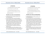
How Your Sediment Backwash Filter Works
Water enters the top of the tank and
flows down through the media and
up the distributor tube.
The downflow type Sediment Filter
removes sediment and can be
backwashed, which cleans and re-
classifies the filter media, preventing
channeling.
During backwash the flow of water is
reversed and water flows down the
distributor tube and up through the
media, lifting and expanding the
Turbidex Media.
During the backwash the filter media
is cleaned by the action of the water
flowing through it.
Fig. 1

www.cleanwaterstore.com Page 5 | 24
System Installation Steps Overview
1. Verify that you have received all parts and there are no damaged or missing parts.
2. Put gravel in first, then Turbidex filter media. Fill tank with clean water. The longer it
soaks while you are doing everything else, the better.
3. Make the plumbing connections from your existing system to the bypass assembly,
installing extra valves, unions, pressure gauges and hose bibs as needed.
4. Attach the control head to the tank, and to the bypass assembly.
5. Install the Drain Line tubing from control valve to a drain with an air gap.
6. Plug in the power supply and program the valve.
7. Follow the instructions to put the system online and to verify the system is leak-free.
Pre-Installation
1. Review your packing list to make sure you have received all the parts before
installation.
2. If you are going to be turning off the water to the house and you have an electric
water heater, shut off the power to the water heater before beginning installation.
3. Pick a suitable location for your filter system on a dry level spot where it won’t be
exposed to freezing temperatures, direct sunlight, wind or rain.
4. Get all of your plumbing parts together before beginning installation.
5. After the system is installed and running, your water may be discolored, or full of
sediment or rust, especially if you have older or corroded piping. This typically
clears up over a day or two.

www.cleanwaterstore.com Page 6 | 24
Best Practices for Piping & Drain Installation
1. See typical installation (Fig 2). The Sediment Backwash Filteris installed after pressure
tank.
2. Install on a level floor or surface.
3. Filter system must be installed at least 10 feet ahead of inlet to water heater to prevent
damage due to back-up hot water or use a check valve to prevent hot water back-up.
4. DO NOT install the unit in an area of direct sunlight or expose to freezing.
5. Locate the unit near an unswitched, 120 volt / 60 Hz grounded electrical outlet.
6. Filter system must be installed at least 10 feet ahead of inlet to water heater to prevent
damage due to back-up hot water or use a check valve to prevent hot water back-up.
7. DO NOT install the unit in an area of direct sunlight or expose to freezing.
8. Locate the unit near an unswitched, 120 volt / 60 Hz grounded electrical outlet.
9. Make sure to connect the IN pipe to the 9510 inlet and the OUT pipe to the outlet.
10. Make sure there is a working gate or ball valve before the 9510 Sediment Filter and also
one after as shown in Fig 2. The pressure gauges are optional. A hose bib (which is a
faucet that you can attach a garden hose to) is strongly recommended after the 9510
Filter and before the second ball valve, for rinsing and sampling water.
11. If you will be using copper piping, do not sweat the copper pipe directly on to the 9510
control valve. Avoid heating up the 9510 control valve plastic with the torch.
12. The drain line tubing is connected to a drain from the drain outlet using flexible poly
tubing. The drain can run up above the control head and out to a drain, although this
may require installing a one way, flapper-stlye check valve.
13. Most plumbing codes require an air-gap connection, so that if your sewer or septic
tank backs up, it cannot cross connect with the drain tubing (if running tubing into the
washing machine drain pipe, for example)


www.cleanwaterstore.com Page 8 | 24
Add Filter Media and Install 9510 Backwash Valve on Tank
1. Make sure you “test fit” distributor tube, find divot that keeps tube centered, before
adding gravel so distributor tube does not extend past top of tank.
2. Cover top of distributor tube with tape so no media enters distributor tube.
3. Hold the tube center until there is enough gravel and media to support the tube. The top
of the distributor tube should be level with the top opening of the filter tank.
4. Add the filter gravel that came with your order. The gravel should cover the bottom
distributor screen before adding the Sediment Filter media.
5. Next add the Turbidex Media.
6. The tank should be about 2/3 full of media, do not fill much more than 2/3 full, even if
there is media left over. We ship the correct amount of media to fill your tank.
7. Fill tank completely with water. Allow to soak for at least 2 hours up to 24 hours before
you hook it up to piping.
8. Remove tape from top of distributor tube. Be careful not to pull up distributor tube.
9. Screw on Control Valve: Add small amount of silicone grease
to both O-rings (only O-rings, not tank thread) on bottom of
control valve and screw on 9510 control valve.
10. Do not lubricate tank threads or any other fittings other than
O-rings. Do not use pipe-joint compound, vegetable oil,
Teflon tape, or Vaseline or greases on tank threads.
11. If you accidentally pull distributor tube up after gravel and
media are in tank it must be re-seated. It is possible to do this
by spraying water down distributor tube with a garden hose
while pushing on end of the tube. If this does not work, you
must empty tank completely and start over.
12. Do not hard pipe the drain line with PVC or copper, use flexible tubing. If you use hard
PVC piping for the drain line, you must able to remove the hard drain piping and attach
flexible tubing for testing purposes.
13. Make sure the drain tubing is firmly clamped to the barbed fitting with a hose clamp to
prevent leaks or blow-offs


www.cleanwaterstore.com Page 10 | 24
Piping Installation
1. If your hot water tank is electric, turn off the power to it to avoid damage to the element
in the tank.
2. If you have a private well, turn the power off to the pump and then shut off the main
water shut off valve. If you have municipal water, simply shut off the main valve. Go to the
faucet, (preferably on the lowest floor of the house) turn on the cold water until all pressure
is relieved and the flow of water stops.
3. Locate the filter tank close to a drain where the system will be installed. The surface
should be clean and level.
4. Connect the inlet and outlet of the filter using appropriate fittings. Perform all plumbing
according to local plumbing codes. Use 3/4” minimum pipe or tubing size for the drain line
ON COPPER PLUMBING SYSTEMS BE SURE TO INSTALL A GROUNDING WIRE BETWEEN THE
INLET AND OUTLET PIPING TO MAINTAIN GROUND-ING.
Any solder joints near the valve must be done before connecting any piping to the valve.
Always leave at least 6" (152 mm) between the valve and joints when soldering pipes that
are connected to the valve. Failure to do this could cause damage to the valve.
5. Connect the drain hose to the valve and secure it with a hose clamp. Run the drain hose
to the nearest laundry tub or drainpipe. This can be ran up overhead or down along the
floor.
If running the drain line more than 20 ft overhead, it is recommended to increase the hose
size to 3/4”.
NEVER MAKE A DIRECT CONNECTION INTO A WASTE DRAIN. A PHYSICAL AIR GAP OF AT
LEAST 1.5” SHOULD BE USED TO AVOID BACTERIA AND WASTEWATER TRAVELLING BACK
THROUGH THE DRAIN LINE INTO THE FILTER.
6. Place the unit in the bypass position.
Make sure there are no leaks in the plumbing system before proceeding.
Note: The unit is not ready for service until you complete the start-up
instructions.

www.cleanwaterstore.com Page 11 | 24
8. Using Teflon tape on pipe threads, make sure to connect the IN pipe to inlet and OUT
pipe to the outlet.
9. Make sure there is a hose bib installed after the system, and a working gate or ball valve
before filter system and also one after as shown in Fig 2. The pressure gauges are
optional but a hose bib is strongly recommended after the 9510 control valve and
before the second ball valve. This makes it easy to rinse your new system on start-up
and gives you a place to test water before it enters your house plumbing.
Start-up Instructions
1. Plug the valve into an approved power source.
2. When power is supplied to the control, the screen will display “Advancing
to Service Wait Please” while it finds the service position.
3. Start an Immediate Manual Regeneration. The valve will immediately start
moving to the BACKWASH position.
4. Open the inlet on the bypass valve slowly and allow water to enter the unit.
Allow all air to escape from the unit before turning the water on fully then
allow water to run to drain for 8 – 10 minutes or until all media fines are
washed out of the filter as indicated by clear water in the drain hose.
5. Press any button to advance to the RINSE position. Check the drain line
flow. Allow the water to run for 8 – 10 minutes or until the water is clear.
6. The valve will automatically advance to the SERVICE position after the RINSE
cycle is complete. Open the outlet valve on the bypass, then open the
nearest treated water faucet and allow the water to run until clear, close the
tap and replace the faucet screen.
7. NOTE: 9510 Sediment Backwash Filter may need to be backwashed and
rinsed several cycles to condition and rinse Turbidex Media on start-up.
8. Next program the time, date, and number of days between regenerations
into controller using Programming Instructions

www.cleanwaterstore.com Page 12 | 24
Programming Settings
MENU
Enter or exit the system menu. Press and hold the button for 3
seconds to
unlock the screen.
SET/REGEN
Press this button to select a program or to save the settings.
Press and hold the button for 3 seconds to initiate a manual
regeneration.
DOWN / UP
Press these buttons to increase or decrease the value of the
settings. Press the
buttons to enter the previous or the next menu.

www.cleanwaterstore.com Page 13 | 24
How To Change Settings
1. Press the MENU button to enter and exit the menu.
2. Press the UP or DOWN button to select the parameter.
3. Press the SET/REGEN button to enter or activate the parameter for editing.
4. Press the UP or DOWN button to change the value.
5. Press the SET / REGEN button to save the value.
6. Press the UP or DOWN button to select other parameters.
7. Follow the above steps to change other parameters.
8. Press the MENU button to save and exit settings
You can only change flashing parameters.
Main Display
When power is first supplied, the valve may take up to two minutes to find
the service position. During this time the valve will show:
Do not touch any buttons at this time. When the valve reaches the service
position it will display:

www.cleanwaterstore.com Page 14 | 24
This page shows the current time, last regeneration day, and the regeneration
mode. The number of blue bars represent the capacity remaining and the flow
rate. The screen will be locked after 3 minutes. To unlock the screen press and
hold the MENU key for 3 seconds.
MANUAL REGENERATION
Press and hold the SET REGEN button for 3 seconds to enter the manual regeneration
page. The screen will display:
If you choose DELAY, the valve will start a regeneration at the next regeneration
time (default is 2:00 AM).
If you choose IMMEDIATE, the valve will start a regeneration immediately.
When a regeneration is started, the screen will display:

www.cleanwaterstore.com Page 15 | 24
When the valve reaches the BackWash position. The screen will display:
When Back Wash remaining time reaches zero or any button is pressed, the valve will
advance to the Rinse position.
Main Program
Press the MENU key to view the main page.
1. Press the MENU button to enter and exit the menu.
2. Press the UP or DOWN button to select the parameter.
3. Press the SET/REGEN button to enter or activate the parameter for editing.
4. Press the UP or DOWN button change the value.
5. Press the SET / REGEN button to save the value.
6. Press the UP or DOWN button to select other parameters.
7. Follow the above steps to change other parameters.
8. Press the MENU button to save and exit settings.
9. You can only change flashing parameters.

www.cleanwaterstore.com Page 16 | 24
Choose Time icon to adjust the current date and time.
Choose Region icon to change the display unit of measures. Choose Language
icon to change the display language. Note English may be only option
depending on version of software.
Choose Holiday Mode icon if you wish to activate it. The system will perform a
brief back wash and rinse every 7 days. When turning Holiday Mode ON,
remember to add the end date. This will ensure the valve will return to normal
operation on that date.

www.cleanwaterstore.com Page 17 | 24
The advanced settings have two options. Choose manual settings.
In Regen Mode you can select four different regeneration modes.
Calendar Clock: the unit will initiate regeneration at the next pre-set
regeneration time based on the interval of days between regeneration days.
Meter Immediate: the unit will initiate regeneration immediately after the
volume remaining reaches zero.
Meter Delayed: this is the most common setting. When the volume
remaining reaches zero, the system will initiate regeneration at the next
preset regeneration time.
Meter Override: when the volume remaining reaches zero, the system will
initiate regeneration at the next pre-set regeneration time. If the days between
regeneration are reached before the volume remaining reaches zero, the
system will override the meter setting and initiate regeneration.


www.cleanwaterstore.com Page 19 | 24
Choose Regen. Days to adjust the interval (days) between regenerations. Set to backwash every
7 days for most applications, although very dirty water or heavy use may require more frequent
backwashes.
Choose Regen. Cycle to adjust the length of time for each cycle. Note that filter valve
mode only has two cycles: Backwash and Rinse. Set backwash for 10 – 15 minutes
&rinse for 6 – 8 minutes. The Sediment Backwash Filteronly uses Backwash and Rinse.
Restore Defaults will erase all the current settings. Be careful when choosing this since
you will lose all the current settings and the default settings loaded back in may not be
the correct settings for your system.

/