Page is loading ...

Ring Alarm Retrofit Kit Manual
Page 1 of 6
Ring Retrofit Alarm Kit
Ring Retrofit Alarm Kit is a Wired-to-wireless bridge that connects to your existing hardwired contact sensors and transmits open/close events wirelessly to Ring
Alarm. Connect up to 8 wired contact sensor zones to the device. Set up and configure the device using the Ring app. After installation and setup, monitor and
receive notifications when doors and windows with wired sensors connected to Retrofit Alarm Kit open and close. The Ring Alarm Base Station is required to
enable Retrofit Alarm Kit features and functions. Once setup, wired sensors connected to Retrofit Alarm Kit can be monitored just like other Ring Alarm sensors in
the system.
Ring Retrofit Alarm Kit - Basic Setup
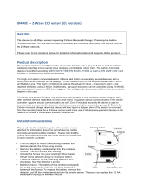
1. Securely mount the Ring Retrofit Alarm Kit to the wall near the wired alarm panel by using the pre-applied double stick tape on
the back of the device or with screws by removing the top cover and inserting the screws through the mounting holes on either side
of the device. The device’s orientation should be such that the screw terminal blocks are facing down, and the batteries are on the
left. Be careful not to mount it inside of a metal box.
2. Disconnect wired contact sensor connections from security panel. (Powered motion sensors are not supported.)
3. Each wired contact in a home security system consists of two wires. Determine the pairs for each.
4. For each pair of wires, connect one of the wires to the Retrofit Alarm Kit’s screw terminal blocks labeled “C” for common, and the
other to an open screw terminal labeled with a number from 1 to 8.
Note:
• This product can be operated in any Z-Wave network with other Z-Wave certified devices from other manufacturers. All mains operated
nodes within the network will act as repeaters regardless of vendor to increase reliability of the network.
• This is a SmartStart enabled product which can be added into a Z-Wave network by scanning the Z-Wave QR Code present on the product
with a controller providing SmartStart inclusion. No further action is required and the SmartStart product will be added automatically within
10 minutes of being switched on in the network vicinity. This product can also be operated in any Z-Wave network with other Z-Wave
certified devices from other manufacturers.

Ring Alarm Retrofit Kit Manual
Page 2 of 6
Installation
1. Securely mount the Ring Retrofit Alarm Kit to the wall near the wired alarm panel by using the pre-applied double
stick tape on the back of the device or with screws by removing the top cover and inserting the screws through the
mounting holes on either side of the device. The device’s orientation should be such that the screw terminal blocks
are facing down, and the batteries are on the left. Be careful not to mount it inside of a metal box.
2. Disconnect wired contact sensor connections from security panel. (Powered motion sensors are not supported.)
3. Each wired contact in a home security system consists of two wires. Determine the pairs for each.
4. For each pair of wires, connect one of the wires to the Retrofit Alarm Kit’s screw terminal blocks labeled “C” for
common, and the other to an open screw terminal labeled with a number from 1 to 8.
Ring Alarm Retrofit – Inclusion
Adding Ring Alarm Retrofit Kit to a Z-Wave Network
Ring Alarm Retrofit Kit can be added via smart start or via classic inclusion mode –
Note: When prompted for the QR Code or PIN, you can find them inside of the top cover of the device, on the box, or on a card inside the box. Keep the device nearby.
You’ll be prompted to pull the battery tab to confirm the connection.
Smart Start Inclusion Steps:
1. Initiate add flow in the Ring Alarm mobile application – Follow the guided add flow instructions provided in the Ring Alarm
Mobile application
2. Scan the QR code found on the package of the Ring Alarm Retrofit Kit or the QR code found on the inside of the top cover of the
device.
4. When the inclusion process in complete, the LED on the keypad will be solid green, then go out.

Ring Alarm Retrofit Kit Manual
Page 3 of 6
Classic Inclusion Steps:
1. Initiate add flow in the Ring Alarm mobile application – Follow the guided add flow instructions provided in the Ring Alarm
Mobile application
2. Select add manually and enter the 5 digit DSK pin found on the package of the Ring Alarm Retrofit Kit or the 5 digit DSK pin
found on the inside of the top cover of the device.
4. When the inclusion process in complete, the LED on the keypad will be solid green, then go out.
Ring Alarm Retrofit – Exclusion
Removing a Keypad to a Z-Wave Network
Exclusion Instructions:
1. Initiate remove keypad flow in the Ring Alarm mobile application – Select the settings icon from device details page and choose
“Remove Device”
2. Press and hold “1” key for three seconds
3. When the exclusion process is complete, the LED on the keypad will be solid blue, then go out
4. Test the Keypad. Any button presses would not beep
Ring Keypad – Reset
Factory Default Instructions
1. Press and hold “5” key and using a pointed end of a paperclip, gently press and release reset button via the reset pinhole found at the
back of the keypad
2. Red network LED at the top left-hand corner will start to blink rapidly
3. Wait for the red LED to stop blinking then release the “5” key
Use this procedure only in the event that the network primary controller is missing or otherwise inoperable.
Wake-Up Notification
The sensor will wake up every so often to send a Wake-Up Notification to allow the life line master node controller that the sensor is
now available for any queued messages that the controller may have for the sensor. The time between Wake-Up Notifications can be
configured with the Wake-Up Notification command class to be between 1 and 24 hours with interval steps of 1 minute.

Ring Alarm Retrofit Kit Manual
Page 4 of 6
Mapping of the Basic Command Class
The device can be queried with Basic for each of its eight endpoints to see if they are 0 (contact closed) or 0xFF (contact open).
Z-Wave Command Classes
Command Class
Version
Z-Wave Plus Info
2
Transport Service V2
2
Security 2
1
Association
2
Association Group Info
1
Multi-Channel Association
3
Multi-Channel
4
Battery
1
Configuration
1
Device Reset Locally
1
Manufacturer Specific
2
Notification
8
Power Level
1
Supervision
1
Wakeup
2
Version
3
Firmware Update MD
4
Basic
2
Association
This sensor has two Association groups with only one node for each group. Group one is a lifeline group who will receive unsolicited
messages relating to case tamper notifications, battery level notifications, Wake-Up notifications, and Device Reset Notifications.
Group two is intended to be used with multi-channel association for a controller to subscribe to contact switch open/close notifications
sent encapsulated from each of the eight endpoints one for each contact switch. Each endpoint must be enabled by putting the
controller’s node ID into the device’s Association Group 2 with either an Association Set encapsulated with Multi-Channel
Encapsulation OR a Multi-Channel Association Set encapsulated with Multi-Channel Encapsulation.

Ring Alarm Retrofit Kit Manual
Page 5 of 6
Example Multi Channel Association Set Command:
Group Identifier
2
Node ID
Blank/Nothing Entered
Marker
0x00
vg
1 (Press plus button to make the variant group
fields appear.)
Multi-Channel Node ID
01 (Controller’s Node ID)
End Point
0x00
Bit Address
Not Selected
Configuration
The sensor has seven supported configuration parameters.
Parameter
Number
Description
Number
of
Bytes
Default
Min
Max
1
Number of seconds between periodic battery reports.
(Heartbeats)
2
4200
(0x1068)
255 (0xFF)
4200 (0x1068)
2
One-Time Wakeup Notification. (In addition to normal
Wakeup Notification)
2
0 (Not in
use).
1 (must be divisible
by sleep step time
of configuration
parameter 7)
3600 (0x0E10)
3
Number of Application Level Retries after a failed
transmission defined as either not ACKed or Supervision
Report not returned when encapsulated.
1
5
1
15
4
The minimum number of seconds to sleep between
application level retries.
1
6
1
60 (0x3C)
5
Application Retry Multiplier. The number of seconds
between a current application retry is the count of retries
multiplied by this number in seconds + a small random
delay.
1
5
1
5
6
The number of milliseconds to wait for a Supervisory
Report in response to a Supervisory encapsulated Get.
2
1500
(0x5DC)
500 (0x1F4)
5000 (0x1388)

Ring Alarm Retrofit Kit Manual
Page 6 of 6
7
The number of seconds the device will sleep between
waking up to increment its Wakeup and Heartbeat counter.
Also the sleep step time.
1
255 (0xFF)
10 (0x0A)
255 (0xFF)
8
Contact Debounce time in 10ms increments.
1
5
1
100
9
Flag to toggle application level retry on missing a
Supervision Report from contact switch inputs. (This is to
be able to test with a PC Controller which by default does
not send Supervision Reports in response to a Supervision
Get when the Supervision Get is encapsulated with a
Multi-Channel Encapsulation.
1
0
(Disabled)
0
1 (Enabled)
Notification Sensor Conditions
SENSOR CONDITION
COMMAND CLASS and VALUE
ASSOCIATION GROUP
Wired Contact Open
Notification Report,
Type: Home Security (0x07)
Event: Intrusion Unknow Location (0x01)
2 (Used with Mutli-Channel Association)
Wired Contact Closed
Notification Report,
Type: Home Security (0x07)
Event: Previous Events Cleared (0x00)
2 (Used with Mutli-Channel Association)
Sensor Case Removed
Notification Report,
Type: Home Security (0x07)
Event: Tampering Product Covering Removed (0x03)
1
Sensor Case Fastened
Wake-Up Notification
1
Notification Report,
Type: Home Security (0x07)
Event: Previous Events Cleared (0x00)
1
Battery Level
A battery report can have the following values: 100 (New Battery), 99
(Good Battery), 0 (Low battery/Should be changed soon), and 0xFF (Dead
Battery/Device is no longer operating).
1
/