Page is loading ...

Sheet No.
Rev. A, August 30, 2007
© 2007 SPX Corporation
Form No. 544303
Parts List &
Operating Instructions
for: 9104B
9110B
Hydraulic Cylinders
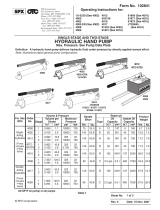
9104B Max. Capacity: 4 Tons
9110B Max. Capacity: 10 Tons
11Cylinder Base
21Pin
31Coupling Ring
41Coupler
51Plug
61O-ring
71Cylinder
81Spring
91Seal
10 1 Nylon Gasket
11 1 Piston Ring
12 1 Piston Rod
13 1 Bushing
14 1 Ram Sleeve
Item
No. Qty. Description
Parts List
Parts List and Replacement Kits for 9104B
1
2
4
5
6
7
8
9
10
11
12
13
14
1 of 4
Item
No. Qty. Description
No. 544763 Seal Kit
61O-ring
91Seal
10 1 Nylon Gasket
11 1 Piston Ring
No. 544790 Spring Kit
21Pin
61O-ring
81Spring
No. 544791 Ram Kit
61O-ring
91Seal
10 1 Nylon Gasket
11 1 Piston Ring
12 1 Piston Rod
No. 544793 Ram Sleeve Kit
14 1 Ram Sleeve
No. 544794 Cylinder Kit
61O-ring
71Cylinder
13 1 Bushing
No. 544795 Base Kit
11Cylinder Base
61O-ring
No. 544788 Ram Half Coupler Kit
31Coupling Ring
41Coupler
51Plug
Item
No. Qty. Description
Replacement Kits
SPX Corporation
655 Eisenhower Drive
Owatonna, MN 55060-0995 USA
Phone: (507) 455-7000
Tech. Serv.: (800) 533-6127
Fax: (800) 955-8329
Order Entry: (800) 533-6127
Fax: (800) 283-8665
International Sales: (507) 455-7223
Fax: (507) 455-7063
9104B
R
3

Item
No. Qty. Description
No. 544766 Seal Kit
91Retainer
10 1 Piston Ring
11 1 O-ring
12 1 Seal
16 1 O-ring
No. 544796 Spring Kit
21Pin
71Spring
16 1 O-ring
No. 544797 Ram Kit
81Retaining Ring
91Retainer
10 1 Piston Ring
11 1 O-ring
12 1 Seal
13 1 Piston Rod
16 1 O-ring
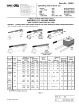
Replacement Kits
11Cylinder Base
21Pin
31Coupling Ring
41Coupler
51Plug
61Cylinder
71Spring
81Retaining Ring
91Retainer
10 1 Piston Ring
11 1 O-ring
12 1 Seal
13 1 Piston Rod
14 1 Fasten Nut
15 1 Reinforced Ring
16 1 O-ring
17 1 Ram Sleeve
Item
No. Qty. Description
Parts List
No. 544799 Ram Sleeve
17 1 Ram Sleeve
No. 544801 Cylinder Kit
61Cylinder
14 1 Fasten Nut
15 1 Reinforced Ring
16 1 O-ring
No. 544802 Base Kit
11Cylinder Base
16 1 O-ring
No. 544788 Ram Half Coupler Kit
31Coupling Ring
41Coupler
51Plug
Item
No. Qty. Description
Parts List and Replacement Kits for 9110B
Parts List & Operating Instructions Form No. 544303, Sheet 1 of 4, Back
1
2
3
4
5
6
7
8
9
11
15
16
17
14
12
10
9110B
13

Sheet No.
Rev. A, August 30, 2007
© 2007 SPX Corporation
Cylinder
Quick
Coupler
Hydraulic
Hose
Gauge
Pump
Single-Acting Hydraulic System
A basic single-acting hydraulic system consists of a manual or power pump that moves the hydraulic fluid, a
hydraulic hose that carries the fluid, and a cylinder or ram that the fluid moves to do a job.
The cylinder, hose(s), couplings, and pump all must be rated for the same maximum operating pressure,
correctly connected, and compatible with the hydraulic fluid used. An incorrectly matched system can cause
the system to fail and possibly cause serious injury. If you are in doubt, consult our Tech. Services Dept. at (800)
533-6127.
INTRODUCTION
These instructions are written to help you, the user, more effectively use and maintain your hydraulic cylinders.
If you have any questions, call your nearest OTC distributor.
Some of the information included in these instructions was selected from the ANSI B30.1 Standards and applies
to the construction, installation, operation, inspection, and maintenance of the hydraulic cylinders. It is strongly
recommended that you read ANSI B30.1 to answer any questions not covered in these instructions. The
complete ANSI B30.1, which contains additional information, can be obtained for a nominal cost by calling the
American Society of Mechanical Engineers at 1-800-843-2763.
TYPICAL INSTALLATION
Since the single-acting cylinders have only one hose going to the cylinder, the cylinder can only apply force to
extend its rod. The return stroke is accomplished by spring force.
Parts List & Operating Instructions Form No. 544303
2 of 4

Safety Precautions
WARNINGS: To prevent personal injury,
•Read and understand all safety precautions and operating instructions before using
this cylinder. If the operator cannot read English, operating instructions and safety
precautions must be read and discussed in the operator’s native language.
-
Si el operador no puede leer inglés, las instrucciones de operación y las precauciones
de seguridad deberán leerse y comentarse en el idioma nativo del operador.
-Si l’utilisateur ne peut lire l’anglais, les instructions et les consignes de sécurité
doivent lui être expliquées dans sa langue maternelle.
•Failure to follow these warnings could cause a loss of load, damage to equipment, and
/ or failure of equipment, which may result in personal injury or property damage.
•Wear eye protection that meets ANSI Z87.1 and OSHA standards.
•When extending a cylinder or ram under load, ensure the couplers or port threads have
not been damaged, and they will not come in contact with any rigid obstruction. If this
condition occurs, the coupler’s attaching threads may become stripped or pulled from
the cylinder or ram, resulting in the release of high pressure hydraulic fluid, flying
objects, and loss of load.
•Avoid off-center loads that could damage the cylinder or ram and/or cause loss of
load. Control the load at all times to prevent thread shearing and loss of load. Ensure
everyone is clear of the load.
•Before operating the pump, all hose connections must be tightened securely and leak-
free—do not overtighten. Overtightening can cause premature thread failure or high
pressure fittings to split at pressures lower than their rated capacities.
•Should a hydraulic hose rupture, burst, or become disconnected, immediately shut off
the pump and release all pressure. Never grasp a leaking pressurized hose with your
hands. The force of escaping fluid could cause serious injury.
•Periodically inspect the hose for wear. Do not subject the hose to potential hazards
such as fire, sharp surfaces, extreme heat or cold, or heavy impact. Do not allow the
hose to kink, twist, curl, crush, cut, or bend so tightly that fluid flow within the hose
is blocked or reduced. These conditions could damage the hose, which could result
in personal injury.
•To prevent deterioration, hoses must not come in contact with corrosive materials, such as creosote-
impregnated objects and some paints. Hose deterioration can result in personal injury. Consult the
manufacturer before painting a hose. Never paint a coupler.
•Do not use the hose to move attached equipment. Stress can damage the hose and possibly cause
personal injury.
•Hose material and coupler seals must be compatible with the hydraulic fluid used. Use only approved
hydraulic fluid.
•Appropriately rated adapters must be installed and used correctly for each application.
•To prevent expelling high pressure oil into the atmosphere, do not extend the cylinder beyond the
suggested maximum stroke. If this does occur, seals must be replaced.
Parts List & Operating Instructions Form No. 544303, Sheet 2 of 4, Back

Sheet No.
Rev. A, August 30, 2007
© 2007 SPX Corporation
Parts List & Operating Instructions Form No. 544303
•Do not exceed the rated capacity of the cylinder. Excess pressure can result in personal injury.
•Inspect each cylinder and coupler before each use to prevent unsafe conditions
from developing. Do not use cylinders if they are damaged, altered, or in poor
condition. Do not use cylinders with bent or damaged couplers or damaged
port threads.
•Under certain conditions, the use of an extension with a hydraulic cylinder may
not be advisable and could present a dangerous condition.
•Avoid pinch points or crush points that can be created by the load or parts of
the cylinder.
•Never use extreme heat to disassemble a hydraulic cylinder or ram. Metal fatigue and/or seal damage
will result and can lead to unsafe operating conditions.
This guide cannot cover every hazard or situation—use the cylinder with SAFETY FIRST.
IMPORTANT:
•Keep the cylinder clean at all times.
•When the cylinder is not in use, keep the piston rod fully retracted and upside down.
•Use an approved, high-grade pipe thread sealant to seal all hydraulic connections. Teflon tape can
be used if only one layer of tape is used, and it is applied carefully (two threads back) to prevent the
tape from being pinched by the coupler and broken off inside the pipe end. Any loose pieces of tape
could travel through the system and obstruct the flow of fluid or cause jamming of precision-fit parts.
•Use protective covers on disconnected quick couplers.
•Limit the stroke on spring return cylinders to prolong spring life.
Set-Up
Hydraulic Connections
Remove thread protectors or dust covers from the hydraulic ports, if applicable. Clean the areas around the fluid
ports of the pump and cylinder. Inspect all threads and fittings for signs of wear or damage, and replace as
needed. Clean all hose ends, couplers, and union ends. Connect all hose assemblies to the pump and cylinder.
Use an approved, high-grade pipe sealant to seal all hydraulic connections. Tighten securely and leak-free, but
do not over tighten.
Hydraulic lines and fittings can act as restrictors as the cylinder or ram retracts. The restricting or slowing of the
fluid flow causes back pressure that slows the cylinder’s or ram’s return. Return speed also varies because of
the application, condition of the cylinder or ram, inside diameter of hose or fitting, length of the hose, and the
temperature and viscosity of the hydraulic fluid.
LOAD
Pinch
Point
CAUTION: Do not allow
the hose to kink, twist,
curl, crush, cut, or bend
so tightly that the fluid
flow within the hose is
blocked or reduced.
3 of 4

Bleeding the System
After all connections are made, the hydraulic system must be bled of any trapped air. Refer to the diagram below.
With no load on the system, and the pump vented and positioned higher than the cylinder or ram, cycle the
system several times. If you are in doubt about venting the pump, read the operating instructions for your pump.
Check the reservoir for possible low fluid level and fill to correct level with approved, compatible, hydraulic fluid
as necessary.
IMPORTANT: Some spring return cylinders, or rams, have a cavity in the rod which forms an air pocket.
This type of cylinder or ram should be bled when positioned upside down or lying on its side with the
port facing upward.
Inspection
Before each use, visually inspect for the following items:
1. Cracked or damaged cylinder
2. Excessive wear, bending, damage, or insufficient part engagement
3. Leaking hydraulic fluid
4. Scored or damaged piston rod
5. Swivel heads and caps not functioning correctly
6. Loose bolts
7. Damaged or incorrectly assembled accessory equipment
8. Modified, welded, or altered equipment
9. Bent or damaged couplers or port threads
Preventive Maintenance (yearly, or sooner if the cylinder or ram condition suggests damage)—Visual
examination by the operator or other designated personnel with a dated and signed equipment record.
Maintenance
Periodic Cleaning
Follow these maintenance tips to keep your equipment in its best working condition:
•Keep the hydraulic system, including hose connections and equipment attached to the cylinder, as free from
dirt and grime as possible. Seal all unused couplers with dust covers.
•Use only OTC hydraulic fluid and change as recommended, or sooner, if the fluid becomes contaminated
(never exceed 300 hours).
•Exposed threads (external or internal) must be cleaned and lubricated regularly, and protected from damage.
•If a cylinder or ram has been exposed to rain, snow, sand, grit-laden air, or any corrosive environment, it must
be cleaned, lubricated, and protected immediately after exposure.
Parts List & Operating Instructions Form No. 544303, Sheet 3 of 4, Back
Cylinder
Pump

Sheet No.
Rev. A, August 30, 2007
© 2007 SPX Corporation
Storage
Cylinders and rams should be stored in a vertical position with the rod end down in a dry, well-protected area,
where they will not be exposed to corrosive vapors, dust, or other harmful elements. When a cylinder or ram
has not been used for three (3) months, it should be connected to a pump, be fully extended and then retracted
to lubricate the cylinder walls, thereby reducing the potential for rust formation.
Troubleshooting Guide
IMPORTANT: The following troubleshooting and repair procedures should be performed by qualified
personnel familiar with this equipment and using the proper equipment.
NOTE:
All the following statements may not apply to your particular model of cylinder or ram. Use the guide
as a general reference for troubleshooting.
Trouble Cause Solution
Erratic action
Cylinder/Ram does not move
Cylinder/Ram extends only
partially
Cylinder/Ram moves
slower than normal
Cylinder/Ram moves but
does not maintain
pressure
1. Air in system or pump cavitation.
2. Internal leakage in double-acting
cylinders or external leakage in single-
acting cylinders.
3. Cylinder sticking or binding.
1. Loose couplers.
2. Faulty coupler.
3. Incorrect pump valve position.
4. Low or no hydraulic fluid in pump
reservoir.
5. Air-locked pump.
6. Pump not operating.
7. Load is above the capacity of the
system.
8. Fluid leaks out of rod end relief valve
(double-acting cylinders only).
1. Pump reservoir is low on hydraulic fluid.
2. Load is above the capacity of the
system.
3. Cylinder piston rod binding.
1. Loose connection or coupler.
2. Restricted hydraulic line or fitting.
3. Pump not working correctly.
4. Cylinder seals leaking.
1. Leaky connection.
2. Cylinder seals leaking.
3. Pump or valve malfunctioning.
1. Add fluid, bleed air, and check for leaks.
2. Replace worn packings. Check for excessive
contamination or wear. Replace contaminated fluid
as necessary.
3. Check for dirt or leaks. Check for bent,
misaligned, worn parts or defective packings.
1. Tighten couplers.
2. Verify the internal coupler is not locked up (ball
wedged into seat). Replace both internal and
external couplers.
3. Close release valve or shift to new position.
4. Fill and bleed the system.
5. Prime pump per pump operating instructions.
6. Check pump’s operating instructions.
7. Use the correct equipment.
8. Verify all couplers are fully coupled. Contact your
nearest Authorized Hydraulic Service Center.
1. Fill and bleed the system.
2. Use the correct equipment.
3. Check for dirt or leaks. Check for bent,
misaligned, worn parts or defective packings.
1. Tighten.
2. Clean and replace if damaged.
3. Check pump operating instructions.
4. Replace worn seals. Check for excessive
contamination or wear.
1. Clean, reseal with thread sealant and tighten
connection.
2. Replace worn seals. Check for excessive
contamination or wear. Replace contaminated fluid
as necessary.
3. Check pump or valve operating instructions.
Parts List & Operating Instructions Form No. 544303
4 of 4

Cylinder/Ram leaks hydraulic
fluid
Cylinder/Ram will not retract or
retracts slower than normal
1. Worn or damaged seals.
2. Loose connections.
1. Pump release valve closed.
2. Loose couplers
3. Blocked hydraulic lines.
4. Weak or broken retraction springs.
5. Cylinder damaged internally.
6. Pump reservoir too full.
1. Replace worn seals. Check for excessive
contamination or wear. Replace contaminated
fluid as necessary.
2. Clean, reseal with thread sealant and
tighten connection.
1. Open pump release valve.
2. Tighten couplers
3. Clean and flush.
4. Send to service center for repair.
5. Send to service center for repair.
6. Drain hydraulic fluid to correct level.
Trouble Cause Solution
Parts List & Operating Instructions Form No. 544303, Sheet 4 of 4, Back
Troubleshooting Guide Contd.
/