Page is loading ...

HYDRAULIC PUMP
Max. Capacity: See Pump Data Plate
Definition: A hydraulic pump delivers hydraulic fluid under
pressure through the use of compressed air, an electric motor,
or a gas engine as a power source.
Form No. 102875
Operating Instructions for:
Electric Motor Powered Pumps
Gas Engine Powered Pumps
Rotary Air Motor Powered Pumps
(As listed in EC Declaration)
dB(A) at
Idle and
Pump kw 700 Bar
PE8 Series .37 67/81
PE17 Series .37 67/81
PA17 Series 1.12 85/90
PE30 Series .74 87/82
PG30 Series 1.49 84/96
PE46 Series 1.12 77/81
PA46 Series 2.24 85/90
PE55 Series .84 87/86
PA55 Series 2.24 87/88
PG55 Series 2.98 75/87
PR10 Series .19 65/72
PG18 Series 1.86 81/96
PG120 Series 4.1 85/95
PQ120 Series 2.24 73/78
PG400 Series 14.9 N/A
66262 2.24 N/A
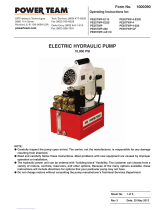
UNIVERSAL
MOTOR
TEFC MOTOR
AIR MOTOR
DC MOTOR
RESERVOIR
GASOLINE
ENGINE
NOTE:
•For a detailed parts list or to locate a Power Team Authorized
Hydraulic Service Center, contact your nearest Power Team facility.
A list of all Power Team facilities is located at the end of this
document.
•Carefully inspect the pump upon arrival. The carrier, not the
manufacturer, is responsible for any damage resulting from
shipment.
•The customer can choose from a variety of motors, controls,
reservoirs, and other options. These instructions will include
directions for options that your particular pump may not have.
•Do not change motors without consulting the pump manufacturer's
Technical Services Department.
QUARTER HORSE
®
12 VDC
Sheet No. 1 of 8
Rev 10 Date: 02 Mar 2005
© 2005 SPX Corporation
Tech. Services: (800) 477-8326
Fax: (800) 765-8326
Order Entry: (800) 541-1418
Fax: (800) 288-7031
SPX Corporation
5885 11th Street
Rockford, IL 61109-3699 USA
Internet Address:
http://www.powerteam.com
®

Operating Instructions, Form No. 102875, Back sheet 1 of 8
SAFETY DEFINITIONS
Safety symbols are used to identify any action or lack of action that can cause personal injury. Your reading
and understanding of these safety symbols is very important.
DANGER - Danger is used only when your action or lack of action will cause serious human injury or
death.
WARNING - Warning is used to describe any action or lack of action where a serious injury can occur.
DANGEROUS VOLTAGE - Dangerous voltage is used to describe any action or lack of action that could
cause serious personal injury or death from high voltage electricity.
IMPORTANT - Important is used when action or lack of action can cause equipment failure, either
immediate or over a long period of time.
SAFETY PRECAUTIONS
These instructions are intended for end-user application needs. Many problems with new equipment are caused by
improper operation or installation. For a detailed parts list or to locate a Power Team Authorized Hydraulic Service
Center contact your nearest Power Team facility. A list of all Power Team facilities is located at the end of this
document.
WARNING: It is the operator's responsibility to read and understand the following
safety statements,
• Only qualified operators should install, operate, adjust, maintain, clean, repair, or
transport this machinery.
• These components are designed for general use in normal environments. These
components are not specifically designed for lifting and moving people, agri-food
machinery, certain types of mobile machinery or special work environments such as:
explosive, flammable or corrosive. Only the user can decide the suitability of this
machinery in these conditions or extreme environments. Power Team will supply
information necessary to help make these decisions.
WARNING: To help prevent personal injury,
GENERAL
• Always wear eye protection whenever operating hydraulic equipment.
• Always wear hearing protection as required. Refer to the sound level (dB[A]) chart.
• Operation, repair, or maintenance of hydraulic equipment should be performed by a qualified person
who understands the proper function of hydraulic equipment per local directives and standards.
• Hydraulic equipment must be assembled correctly and then checked for proper function before use.
Use hydraulic components of the same hydraulic pressure ratings. An appropriate hydraulic pressure
gauge is recommended to monitor pressure.
• Never place your hands or other body parts near a hydraulic fluid leak.
Never use your hands or other body parts to check for a possible leak.
High pressure fluid can be injected under your skin causing serious injury
and/or infection.

Operating Instructions Form No. 102875
SAFETY PRECAUTIONS (GENERAL) CONTINUED -
• High pressure fluid is present throughout a hydraulic system. Always use caution when operating,
repairing, or maintaining this equipment. Before beginning any work on any hydraulic system
component, stop the equipment, disconnect from its power source, and relieve all pressure in all parts
of the system. Do not tamper with the internal hydraulic relief valve settings.
• Avoid exposing hydraulic equipment (especially hoses) to extreme high or low temperatures. Damage
to equipment or failure may result and cause loss of control or injury to the operator.
• Exercise caution to avoid the risk of fire.
• Do not drop any hydraulic system components. Damage to the equipment and/or injury may result.
• Avoid slipping or falling by cleaning up any oil spills.
• Avoid back injury by always lifting equipment carefully.
• It is strongly recommended to view the Power Team Hydraulic Safety video tape before using hydraulic
equipment.
POWER SUPPLY
Electric
Electrical Shock or Electrocution
• Any electrical work must be done and tested by a qualified electrician per local directives and
standards.
• Disconnect the pump from the power supply and relieve pressure before removing the motor case
cover or performing maintenance or repair.
• Never use an ungrounded power supply with this unit.
• If the power cord is damaged or wiring is exposed, replace or repair immediately.
• Changing the voltage on this unit is an involved, and if improperly performed, hazardous procedure.
Consult the manufacturer for specific information before attempting any rewiring.
• All PE55 Series pump motors must be wired for clockwise (CW) rotation when viewed from the lead end
(top) of the motor. PE8 Series, PE17 Series, PE30 Series, PR10 Series, and PE46 Series pump motors
must be wired for counterclockwise (CCW) rotation when viewed from the lead end (top) of the motor.
• Check the
total
amperage draw for the electrical circuit you will be using. (For example: Do not plug a
pump or pumps that may draw 25 amps into a 20 amp fused electrical circuit.)
• Do not attempt to increase the powerline capacity by replacing a fuse with another fuse of higher value.
Overheating of the powerline and the possibility of a fire will result.
• To rewire a motor from one voltage to another or when a flow control valve is changed between manual
and solenoid, consult the electrical schematic in the pump's parts list.
• Electric pumps should never be exposed to rain or water which could cause personal electrical hazard.
• Avoid conditions which can cause damage to the power cord such as abrasion, crushing, sharp cutting
edges, or corrosive environment. Damage to the power cord can cause an electrical hazard.
Gasoline Engine
No Smoking No Open Flame Flammable
• Read the instruction manual for the gasoline engine before using for correct operating procedure.
• Turn off the engine and relieve pressure when not in use or when working on any part of the system.
• Proper ventilation is critical during refueling.
• Do not allow fuel to splash on the engine when refueling.
• Do not add fuel when the engine is running or hot. Sheet No. 2 of 8
Rev 10 Date: 02 Mar 2005

Operating Instructions, Form No. 102875, Back sheet 2 of 8
SAFETY PRECAUTIONS (POWER SUPPLY) CONTINUED -
Air Driven Motor
• A quick disconnect must be installed in the air line to the pump.
• Disconnect air supply and relieve pressure when pump is not in use or when breaking any
connection in the hydraulic system.
• Control circuit must comply with local directives and standards.
HYDRAULIC HOSES AND FLUID TRANSMISSION LINES
•Avoid straight line tubing connections in short runs. Straight line runs do not provide for expansion and
contraction due to pressure and/or temperature changes. See diagrams in “Set-up Instructions” section
of this form.
•Eliminate stress in the tube lines. Long tubing runs should be supported by brackets or clips. Tubes
through bulkheads must have bulkhead fittings. This makes easy removal possible and helps support the
tubing.
•Before operating the pump, all hose connections must be tightened with the proper tools. Do not
overtighten. Connections should only be tightened securely and leak-free. Overtightening can cause
premature thread failure or high pressure fittings to split at pressures lower than their rated capacities.
•Should a hydraulic hose ever rupture, burst, or need to be disconnected, immediately shut off the pump
and release all pressure. Never attempt to grasp a leaking pressurized hose with your hands. The force of
escaping hydraulic fluid could cause serious injury.
•Do not subject the hose to potential hazard such as fire, sharp surfaces, extreme heat or cold, or heavy
impact. Do not allow the hose to kink, twist, curl, crush, cut, or bend so tightly that the fluid flow within
the hose is blocked or reduced. Periodically inspect the hose for wear, because any of these conditions
can damage the hose and possibly result in personal injury. Never repair with tape.
•Do not use the hose to move attached equipment. Stress can damage the hose and possibly cause
personal injury.
•Hose material and coupler seals must be compatible with the hydraulic fluid used. Hoses also must not
come in contact with corrosive materials such as creosote-impregnated objects and some paints. Hose
deterioration due to corrosive materials can result in personal injury. Consult the manufacturer before
painting a hose. Never paint a coupler.
PUMP
•Do not exceed the hydraulic pressure rating noted on the pump nameplate or tamper with the internal
high pressure relief valve. Creating pressure beyond rated capacities can result in personal injury.
•Before replenishing the fluid level, retract the system to prevent overfilling the pump reservoir or bladder.
An overfill can cause personal injury due to excess reservoir or bladder pressure created when the
cylinders are retracted.
•Always shut off the motor or engine and relieve pressure before breaking any connections in the system.
•The motor or engine is the major part of the weight of the pump. Always take this into consideration
when lifting or moving the pump.
CYLINDER
•Do not exceed the rated capacities of the cylinders. Excess pressure can result in personal injury.
•Do not set poorly balanced or off-center loads on a cylinder. The load can tip and cause personal injury.
•Read and understand the cylinder operating instructions and warning decals before using the cylinder.
DANGER: A double-acting cylinder or ram must have both hoses and all couplers
securely connected to both ports. If one of the two ports is restricted or
becomes disconnected, pressure will build and the cylinder, hose or coupler
can burst, possibly causing serious injury or death.
HYDRAULIC FLUIDS
•Properly dispose of all fluids, components, and assemblies at the end of their useful life.
•Hydraulic fluid should be compatible with all hydraulic components.

Operating Instructions Form No. 102875
SET-UP INSTRUCTIONS
Filling The Pump Reservoir Or Bladder
NOTE: Most pumps are shipped without hydraulic fluid in the reservoir. Hydraulic fluid may have been
shipped with the pump in a separate container. If hydraulic fluid is needed, use 215 SSU @ 100° F (47 cSt @
38° C) hydraulic fluid. Pumps with a bladder are shipped with hydraulic fluid in the bladder.
1. Clean the area around the filler cap to remove all dust and grit. Any dirt or dust in the hydraulic fluid can damage
the polished surfaces and precision-fit components of this pump.
2. Retract all cylinder(s) to their return position.
3. Remove the filler cap and insert a clean funnel with a filter. Fill the reservoir with hydraulic fluid to 1" (25,4 mm)
(PE8, PE17 & PE30 series pumps to 1-1/2" [38,1 mm]) from the cover plate. PR10 series pump bladder must be
filled completely. Replace the filler cap. IMPORTANT: For PR10 series pumps, tighten filler cap 1/2 - 1 turn
after o-ring contacts sealing surface. Overtightening can cause pump damage on bladder equipped
pumps.
Hydraulic Connections
Remove the thread protectors or dust covers from the hydraulic ports if applicable. Clean the areas around the fluid
ports of the pump and cylinder. Inspect all threads and fittings for signs of wear or damage, and replace as needed.
Clean all hose ends, couplers and union ends. Connect all hose assemblies to the pump and cylinder. Use an
approved, high-grade pipe thread sealant to seal all hydraulic connections. Tighten securely and leak-free but do not
overtighten.
Hydraulic lines and fittings can act as restrictors as the cylinder or ram retracts. The restricting or slowing of the fluid
flow causes back pressure that slows the cylinder’s or ram’s return. Return speed also varies because of the
application, condition of the cylinder or ram, inside diameter of hose or fitting, length of the hose, and the temperature
and viscosity of the hydraulic fluid.
HOSES TUBING
Bleeding The System
After all connections are made, the hydraulic system must be bled of any trapped air. Refer to the diagrams below.
With no load on the system and the pump vented and positioned higher than the cylinder or ram, cycle the system
several times. Check the reservoir for possible low fluid level and fill to proper level with approved, compatible
hydraulic fluid as necessary (see “Filling The Pump Reservoir Or Bladder” section under Set-up Instructions).
Sheet No. 3 of 8
Rev 10 Date: 02 Mar 2005
INCORRECT
CORRECT
CORRECT CORRECT
INCORRECT INCORRECT
IMPORTANT: Some spring
return cylinders or rams have
a cavity in the rod which
forms an air pocket. This type
of cylinder or ram should be
bled when positioned upside
down or lying on its side with
the port facing upward.
System with a
single-acting
cylinder
System with a
double-acting
cylinder

Operating Instructions, Form No. 102875, Back sheet 3 of 8
PUMP OPERATION
When operating the pump for the first time:
1. Valve and hose connections must be tight, and the reservoir or bladder must be filled to the proper fluid level. Start
the motor.
2. Jog the pump several times to build pressure.
3. Run cylinder out to its full travel several times to eliminate air from the system. For more complete instructions,
refer to the section titled “Bleeding The System” under Set-up Instructions.
4. With the cylinder(s) retracted completely, check the fluid level in the reservoir or bladder and add fluid if necessary.
Refer to “Filling The Pump Reservoir Or Bladder” under Set-up Instructions.
5. The pump is now ready to be put into regular operation.
DANGER: When lifting or lowering a load, the load must be under operator control at all times and
others must be clear of the load. Use blocking and cribbing to guard against a falling load.
Do not drop the load. The use of a load lowering or metering valve is recommended in
addition to the pump directional control valve.
ELECTRIC PUMP
Universal Motor: The universal motor is wired for 115 or 230 volts, 50/60 cycles according to the customer's
request. This motor cannot be rewired.
TEFC and DC Motors: See pump data plate for voltage, frequency, current, and power specifications.
If rewired, retesting may be required per local directives and standards. PR10 series
pump voltage is 12 VDC and is not changeable.
1. Place the valve in neutral position.
2. Plug in the pump.
3. Start the pump and shift as required.
4. Turn the pump off when not in use.
Note: For specific function of your pump see the “Valve Options” section of this form.
IMPORTANT:
• Correct voltage is required for the pump to operate properly.
■■Low voltage may cause: overheated motor; motor fails to start under load; motor
surging when trying to start; or motor stalls before maximum pressure is reached.
■■Check the voltage rating on the pump motor name plate to be certain the outlet or power source you
are using is of the proper voltage.
■■Always check the voltage at the motor with the pump running at full pressure.
• Never run the motor on long, light gauge extension cords. Refer to the minimum recommended gauge
chart below.
Electrical Cord Size AWG (mm2) 3.2 Volt Drop
AMPS
At Maximum Length of Electrical Cord
Hyd. Pressure 0-25 ft. (0-8 m) 25-50 ft. (8-15 m) 50-100 ft. (15-30 m) 100-150 ft. (30-46 m)
6 18 (.82) 16 (1.33) 14 (2.09) 12 (3.32)
10 18 (.82) 14 (2.09) 12 (3.32) 10 (5.37)
14 16 (1.33) 12 (3.32) 10 (5.37) 8 (8.37)
18 14 (2.09) 12 (3.32) 8 (8.37) 8 (8.37)
22 14 (2.09) 10 (5.37) 8 (8.37) 6 (13.30)
26 12 (3.32) 10 (5.37) 8 (8.37) 6 (13.30)
30 12 (3.32) 10 (5.37) 6 (13.30) 4 (21.29)

Operating Instructions Form No. 102875
PUMP OPERATION CONTINUED -
GAS PUMP
Gasoline-Powered: Consult the instruction manual for the gasoline engine to determine its specifications.
1. Place the valve in the neutral or hold position.
2. Start the gas engine according to the operating instruction manual provided.
3. When the engine is running properly, shift the valve as necessary.
4. Turn the pump off when not in use.
AIR PUMP
Rotary Air Motor: Remove the thread protectors from the air inlet, and install the air supply fittings (not
supplied) as shown in Figure 1. Air supply must be minimum 50 CFM (1,4 M3/min.) and 80
PSI (5,5 BAR), with 100 PSI (7 BAR) maximum.
1. Place the valve in the neutral or hold position.
2. Couple the air pump to the air supply and turn on the supply valve (if provided).
3. Open (or turn on) the air supply control valve at the pump (hold-to-run hand control is provided).
4. Shift the pump as necessary.
5. Turn the pump off when not in use.
6. Use of an air filter/lubricator is recommended.
Figure 1
Recommended Air Line Hook-up
Reducing Bushing
Hose
Lubricator
Filter
To air
source
or
supply
Quick Coupler
locate in
system
here or ...
here
here
Hold-to-run
Hand Control
(provided)
Air
Motor
Sheet No. 4 of 8
Rev 10 Date: 02 Mar 2005

Operating Instructions, Form No. 102875, Back sheet 4 of 8
DIRECTIONAL CONTROL VALVE OPTIONS
NOTE: • Some valves return fluid to the reservoir or bladder when the pump stops or when the valve is
shifted. The correct valve must be used, especially when lifting a load.
• "Hold-to-run" controls are recommended and must be used with correct valves for certain
applications, especially when lifting a load.
• Not all valves fit on all pumps.
DANGER: When lifting or lowering a load, the load must be under operator control at all times and
others must be clear of the load. Use blocking and cribbing to guard against a falling load.
Do not drop the load. The use of a load lowering or metering valve is recommended in
addition to the pump directional control valve.
2-Position, 2-Way Manual Valve Used With Single-acting Cylinder
FOR PE17 SERIES (9517)
FOR PE30, PE46, AND
FOR PR10 SERIES (9561) PE55 SERIES (9584)
Figure 1
3-Position, 3-Way Manual Valve Used With
Single-acting Cylinders
9520
1. To hold pressure, turn the valve control handle
clockwise (CW).
2. Activate the pump unit to advance the cylinder.
3. When the cylinder has advanced to the desired
position, deactivate the switch or remote switch, or turn
the pump unit OFF, or shift the valve to the center
position. The cylinder will HOLD pressure.
4. To retract the cylinder, turn the valve control handle
counterclockwise (CCW) slowly.
1. To HOLD pressure, turn the valve control handle
counterclockwise (CCW).
2. Activate the pump unit to advance the cylinder.
3. When the cylinder has advanced to the desired position,
deactivate the switch or remote switch, or turn the pump unit
OFF. The cylinder will HOLD pressure.
4. To retract the cylinder, turn the valve control handle
clockwise (CW) slowly.
WARNING: Valve 9517 and 9561 work the same as a
manifold if the pump is operated with the valve in the
RELEASE position. In this position, the cylinder will
advance when the pump is running and
retract
when the
pump is stopped.
DANGER: Never use valve 9517 and 9561 in the
RELEASE position when lifting a load!
PT
A
Gauge
PT
A
Gauge
WARNING: When the valve is in the ADVANCE position, the cylinder will advance when the pump is
running, and hold when the pump is stopped or the valve is in the CENTER position. The cylinder can be
retracted by moving the valve to the RETRACT position.
2-position, 2-way
Manual Valve
Port
Gauge
Gauge

Operating Instructions Form No. 102875
VALVE OPTIONS CONTINUED -
3-Position, 4-Way Manual Valve used with Double-acting Cylinders
9500 (non posi-check) 9506 (with posi-check) 9511 (non posi-check)
NOTE:
•This valve is a low torque design for use with double-acting or single-acting cylinder(s).
•If this valve is to be used as a 3-way with single-acting cylinder(s), one port (A or B) must remain plugged
(use steel plug).
•Valve handle can be moved to the desired position by loosening the cap screw and rotating in increments
of 22-1/2°.
1. Position the valve control lever in the NEUTRAL or HOLD position.
2. Activate the pump unit.
3. Advance the cylinder by shifting the valve control lever to the ADVANCE position.
4. When the cylinder has advanced to the desired position, turn the pump unit OFF, or shift the valve to the HOLD
position.
NOTE: Non "posi-check" valves will momentarily lose pressure when shifting to HOLD position. See
"posi-check" valve section of this form.
5. Retract the cylinder by shifting the valve control lever to the RETRACT position.
6. Activate the pump unit if using double-acting cylinders.
Examples of typical workholding applications:
SINGLE-ACTING CYLINDER(S) IN THE CIRCUIT DOUBLE-ACTING CYLINDER(S) IN THE CIRCUIT
CONTROLLED BY A PUMP-MOUNTED VALVE CONTROLLED BY A PUMP-MOUNTED VALVE
Other valves are available.
Consult your dealer, catalog or valve
operating instructions for details of operation.
PT
AB
Gauge
PT
AB
Gauge
PT
AB
Gauge
Gauge Gauge Gauge
Port "A"
Valve Handle
Double-
acting
Cylinders
Tees or
Manifolds
Valve
Valve
Single-acting
Cylinders
Port is
plugged
"Y" Manifold
2-Position 3-Position
Cap Screw
Stem
Port "B"
Leave
plugged if
using only
one port
Figure 2 Figure 3
Sheet No. 5 of 8
Rev 10 Date: 02 Mar 2005

Operating Instructions, Form No. 102875, Back sheet 5 of 8
VALVE OPTIONS CONTINUED -
9505
Figure 4
9610
Solenoid Controlled, Pilot Operated Valve Used With Single-acting Cylinders
OPERATION
Neutral (HOLD): When neither solenoid is energized, fluid from pump is
directed back to tank and fluid from cylinder is checked in the cylinder.
Advance: When solenoid "B" is energized, fluid from pump is directed
through pressure port to cylinder.
Return: When solenoid "A" is energized, fluid from the pump and from the
cylinder is directed back to tank. 9599
NOTE: Pressure holds without loss when shifted from cylinder port to the neutral (HOLD) position.
Solenoid Controlled, Pilot Operated Valve Used With Double-acting Cylinders
OPERATION
Neutral (HOLD): When both solenoids are de-energized, fluid from
pump circulates at free flow from the pressure port "P" to tank "T". Both
cylinder ports are blocked.
Solenoid "A" Energized: Pressure to cylinder port "A".
Cylinder port "B" to tank.
Solenoid "B" Energized: Pressure to cylinder port "B".
Cylinder port "A" to tank. 9512
NOTE: Pressure holds without loss when shifted from
cylinder port to the neutral (HOLD) position.
Automatic Dump Valve
1. Activate the pump unit to advance the cylinder.
2. Release the remote switch to release pressure and retract the cylinder.
DANGER: Never use this valve for lifting a load!
"Posi-Check" Valves
If a "Posi-Check" open center valve is used, a hydraulic gauge in
the gauge port shows zero pressure when the valve is switched to
the neutral (hold) position. Cylinder pressure, however, is held
without loss. If reading the cylinder pressure, a gauge must be
installed in the outlet port of the valve.
To install a hydraulic gauge (refer to Figure 4):
1. Remove the pipe plug from the valve's gauge port.
2. Install a steel 45° elbow fitting.
3. Install the gauge into the 45° elbow fitting.
PT
A
Gauge
PT
A
Gauge
Gauge
Gauge
Gauge (Outlet Port)
Gauge to
measure pump
pressure
Gauge to
measure cylinder
pressure
(optional)
Tee Fitting
(optional) Elbow Fitting
PT
A
PT
AB

Operating Instructions Form No. 102875
VALVE OPTIONS CONTINUED -
Solenoid Controlled, Air Operated Valve Used With Single- or Double-acting Cylinders
OPERATION
Position "A" (Air Port "A"): Pressure to Port "A". Port "B" to tank.
Position "B" (Air Port "B"): Pressure to Port "B". Port "A" to tank.
NOTE: All ports open to tank during transition
between valve positions.
9594
Figure
ADJUSTING THE PRESSURE REGULATING CONTROLS
The pressure regulating valve and pressure switch are shown in Figure 6. The pressure regulating valve can be
adjusted to bypass fluid at a given pressure setting while the pump continues to run. The pressure switch can be
adjusted to stop the pump at a given pressure setting. To ensure accuracy and low pressure differential (approx. 300
PSI [21 BAR]) throughout the pressure range (1,000 to 10,000 PSI [70 to 700 BAR] depending on the pump model),
the pressure switch should be used with the pressure regulating valve. The pressure switch must be set at a pressure
lower than the pressure regulating valve to work properly.
PT
A B
Gauge
Gauge
Single-acting, Spring Return Cylinder: Either fluid port "A" or
"B" must be plugged with a steel plug on the valve. With port
"B" plugged, the sequence of operation is as follows: When
solenoid is energized to position "A", fluid port "A" becomes
pressurized. When solenoid is energized to position "B", fluid
port "A" becomes the return port.
Double-acting Cylinders: When operating double-acting
cylinders, fluid port "A" can be connected to either the advance
or return port of the cylinder and fluid port "B" will be connected
to the remaining port. Sequence of operation is as follows:
When solenoid is energized to position "A", port "A" becomes
pressurized and extends the cylinder and fluid port "B" becomes
the return port. When solenoid "B" is energized, the opposite of
step 1 happens.
The application in Figure 5 represents a typical set-up using a
control valve and multiple double-acting cylinders (one double-
acting cylinder may be used). Interflow will occur.
If a different set-up or cylinder is being considered, contact your
nearest Power Team facility.
Pump-
mounted
Valve
Sheet No. 6 of 8
Rev 10 Date: 02 Mar 2005

Operating Instructions, Form No. 102875, Back sheet 6 of 8
ADJUSTING THE PRESSURE REGULATING CONTROLS CONTINUED -
Adjusting The Pressure Regulating Valve
NOTE: For easy adjustment of the pressure regulating valve, always adjust the pressure by
increasing
to the
desired pressure setting.
1. Loosen the locknut (B) on the pressure regulating valve, and back the adjusting screw or knob (A) out a few turns
by turning it in a counterclockwise (CCW) direction. This will
decrease
the setting to a lower than desired pressure.
2. The pump must be completely connected electrically and hydraulically. Start the pump.
3. Slowly turn the adjusting screw or knob (A) in a clockwise (CW) direction. This gradually
increases
the pressure
setting. When the desired pressure is reached, lock the adjusting screw (A) in position by tightening the locknut
(B). Shut off the pump.
IMPORTANT:
•The pressure range is from 1,000 to 10,000 PSI (70 to 700 BAR) depending on the pump model.
•The pressure switch must be set at a higher pressure than working range to prevent shut down during
adjustment.
Figure 6
Figure 7
NOTE: When the pressure switch setting is reached, the motor will shut off. However, the inertia of the motor
continues to deliver fluid for a brief period. The pressure regulating valve bypasses this surplus hydraulic
fluid, preventing it from going into the system. As a result, the pressure differential can be held to
approximately 300 PSI (21 BAR).
QUARTER HORSE®
B
A
Pressure
Switch
Adjusting The Pressure Switch
Generally, the pressure switch should be used with the pressure regulating
valve. A pressure switch can be used
alone
for operating electrical devices
such as motors, solenoids, relays, etc., which are located elsewhere in the
circuit. Refer to Figure 7.
1. Loosen the locknut (B) on the pressure switch, and turn adjusting screw
(A) in a clockwise (CW) direction. This
increases
the pressure setting to a
higher than desired pressure.
2. Adjust the pressure regulating valve to the desired pressure setting. Refer
to the section titled “Adjusting The Pressure Regulating Valve”.
3. With the pump running and bypassing fluid at the desired pressure,
slowly turn the pressure switch adjusting screw (A) in a counterclockwise
(CCW) direction,
decreasing
the pressure switch setting until the pump
motor shuts off. Then lock the adjusting screw (A) in position by tightening
the locknut (B).
4. Release pressure. Run the pump to check the pressure setting and cut-
out of the motor. If may be necessary to make a second adjustment.
B
A

Operating Instructions Form No. 102875
PREVENTIVE MAINTENANCE
WARNING: To help prevent personal injury,
•Disconnect the pump from the power supply before performing maintenance or repair procedures.
•Repairs and maintenance are to be performed in a dust-free area by a qualified technician.
Checking The Hydraulic Fluid And Filling The Reservoir (Except Bladder Type, See Below)
The hydraulic fluid level should be checked after initial set-up and after each ten hours of use.
1. Thoroughly clean the area around the filler cap with a clean cloth to prevent contamination of the hydraulic fluid.
2. Cylinder(s) must be fully retracted and the power supply disconnected.
3. Remove the filler cap and insert a clean funnel with filter. Fill to proper level as instructed in “Filling The Pump
Reservoir Or Bladder” under Set-up Instructions.
4. Replace filler cap.
5. The frequency of fluid changes will depend upon the general working conditions, severity of use, and overall
cleanliness and care given the pump. Three hundred hours of use under general shop conditions is considered a
standard change interval. Drain, clean, and refill the reservoir with a high grade hydraulic fluid.
Checking The Hydraulic Fluid And Filling The Bladder
The hydraulic fluid level should be checked after initial set-up and after each ten hours of use.
1. Thoroughly clean the area around the filler cap with a clean cloth to prevent contamination of the hydraulic fluid.
2. Cylinder(s) must be fully retracted and the power supply disconnected. Position the pump with the filler plug in the
up (or vertical) position.
3. Remove the filler cap and insert a clean funnel with filter. Fill the bladder completely full with a high grade
hydraulic fluid.
4. Replace filler cap. IMPORTANT: Tighten filler cap 1/2 - 1 turn after o-ring contacts sealing surface.
Overtightening can cause pump damage on bladder equipped pumps.
5. The frequency of fluid changes will depend upon the general working conditions, severity of use, and overall
cleanliness and care given the pump. Three hundred hours of use under general shop conditions is considered a
standard change interval. Drain, clean, and refill the reservoir with a high grade hydraulic fluid.
Maintenance Cleaning
IMPORTANT: Never use a high pressure washer to clean hydraulic components!
1. Keep the pump's outer surface as free from dirt as possible.
2. Seal all unused couplers with thread protectors.
3. Keep all hose connections free of dirt and grime.
4. The breather-hole in the filler cap must be clean and unobstructed at all times.
5. Equipment connected to the pump must be kept clean.
6. Use a high grade hydraulic fluid in this pump. Change as recommended (every 300 hours). Some conditions may
require the use of different viscosity hydraulic fluids.
Lubrication (Air Driven Motor Only)
If the pump is operated on a continuous duty cycle or a maximum speeds for extended periods, an automatic air line
oiler should be installed in the air inlet line as close to the pumping unit as possible. Set the unit to feed 1-3 drops of
oil per minute (one drop for every 65 CFM [1,8 M3/min.] of air) into the system, or refer to the pump manufacturer's
instructions. Use SAE No. 10 oil.
Engine Oil (Gas Engine Only)
Change engine oil as recommended for four stroke engines.
Mix the correct oil into fuel in proper ratio as recommended for two stroke engines.
Reservoir Vent Air Filter (Optional for all pumps except PR10 series)
1. Remove the filler cap, and insert either the 45° fitting or the straight fitting. Fasten o-ring end of fitting into pump.
2. If the 45° fitting is used, place the rubber spacer (included) on the top threaded portion.
Then thread the air filter on and hand tighten.
3. If the straight fitting is used, thread the air filter on and hand tighten. Sheet No. 7 of 8
Rev 10 Date: 02 Mar 2005

Operating Instructions, Form No. 102875, Back sheet 7 of 8
PREVENTIVE MAINTENANCE CONTINUED -
Draining And Cleaning The Reservoir (Except Bladder Type, See Below)
IMPORTANT: Clean the pump exterior before the pump interior is removed from the reservoir.
1. Remove the screws fastening the motor and pump assembly to the reservoir. IMPORTANT: Do not damage the
gasket or pump filter or pressure regulating valves when lifting the pump and motor off the reservoir.
2. Clean the inside of the reservoir and clean the filter.
3. Place the pump and motor assembly back onto the reservoir, and secure with machine screws.
4. Fill the reservoir with a clean, high grade hydraulic fluid (refer to “Filling The Pump Reservoir Or Bladder” under
Set-up Instructions for proper fluid level for your pump).
Draining And Cleaning The Bladder
IMPORTANT: Clean the area around the filler hole to prevent contamination of the hydraulic fluid.
1. Remove the filler plug and drain hydraulic fluid completely.
2. Fill bladder half full with clean hydraulic fluid. Flush bladder with clean fluid and drain. IMPORTANT: Never use
solvents to clean the bladder! Never disassemble the bladder from the pump!
3. Fill the bladder completely full with a clean, high grade hydraulic fluid.
TROUBLE-SHOOTING GUIDE
WARNING
•To help prevent personal injury, any repair work or trouble-shooting must be done by qualified personnel
familiar with this equipment.
•Use the proper gauges and equipment when trouble-shooting.
NOTE:
•For a detailed parts list or to locate a Power Team Authorized Hydraulic Service Center contact your
nearest Power Team facility.
•It is best to check for system leaks by using a hand pump and applying pressure to the suspect area.
Watch for leaking fluid and follow it back to its source.
Never
use your hand or other body parts to check
for a possible leak.
Electric motor does not run
WARNING: To help prevent
personal injury, disconnect power
supply before removing cover.
Any electrical work should be
performed by a qualified
electrician.
1. Pump not turned ON.
2. Unit is not plugged in.
3. No voltage supply.
4. Pressure switch not set properly.
5. Broken lead wire or defective
power cord plug.
6. Overheated motor has caused
overcurrent protection to
disengage.
1. Set switch to "ON" position.
2. Plug in unit.
3. Check line voltage. Check reset
button or fuse on power panel.
4. Refer to "Adjusting The
Pressure Switch" information
under "Adjusting The Pressure
Regulating Controls" section.
5. Contact a Power Team
Authorized Hydraulic Service
Center.
6. Wait for motor to cool before
restarting.
Electric motor stalls, surges,
overheats or will not start under a
load.
1. Low voltage or electrical cord
size too small.
1. Refer to the "Electric Pump"
information under "Pump
Operation" section.
Electric motor will not shut off. 1. Defective motor controls. 1. Disconnect from power supply
and contact a Power Team
Authorized Hyd. Service Center.
PROBLEM CAUSE SOLUTION

Operating Instructions Form No. 102875
TROUBLE-SHOOTING GUIDE CONTINUED -
Pump builds pressure but cannot
maintain pressure.
1. External leaks.
2. Internal or external leakage on
hydraulic cylinder.
3. Leaking control valve or check
valve.
1. Seal leaking pipe fittings with
pipe sealant. Replace leaking
pipes or hoses.
2. Remove the cylinder from
pump. If the pump builds and
maintains full pressure, the
cylinder is defective. Contact a
Power Team Authorized
Hydraulic Service Center.
3. Contact a Power Team Author-
ized Hyd. Service Center.
PROBLEM CAUSE SOLUTION
Pump is not delivering fluid or
delivers only enough fluid to
advance cylinder(s) partially or
erratically.
1. Fluid level too low.
2. Quick disconnect couplings are
not completely coupled.
3. Air in system.
4. Cold fluid or fluid too viscous.
5. Reservoir capacity is too small
for the size of cylinder(s) used.
6. Three phase motor rotating in
wrong direction.
7. PR10 series pump not
connected to correct 12 VDC
polarity.
8. Vacuum in reservoir.
1. Fill reservoir or bladder
according to directions “Filling
The Pump Reservoir Or
Bladder” under “Set-up
Instructions” section
2. Check quick-disconnect
couplings to cylinders to ensure
that they are completely
coupled. Occasionally couplers
have to be replaced because
the ball check does not stay
open due to wear.
3. Refer to the section titled
"Bleeding the System" under
“Set-up Instructions” section.
4. Hydraulic fluid is of a higher
viscosity than necessary.
Change to a lighter fluid.
5. Use smaller cylinder(s) or
larger reservoir.
6. Refer to electrical schematic on
motor.
7. Connect to correct 12 VDC
polarity.
8. Check for plugged vent in filler
plug.
Sheet No. 8 of 8
Rev 10 Date: 02 Mar 2005
Electrical overload protector
keeps tripping.
1. Wired incorrectly. 1. See Service Bulletin #9903PT at
the end of this document.
Pump will not build full pressure. 1. Faulty pressure gauge.
2. Check for external leakage.
3. Improperly adjusted external
pressure regulator setting.
4. Internal or external leakage on
hydraulic cylinder.
1. Calibrate gauge.
2. Seal faulty fittings with sealant.
Replace leaking pipes or hoses.
3. Refer to "Adjusting The
Pressure Regulator Valve"
information under "Adjusting the
Pressure Regulating Controls"
section.
4. Remove the cylinder from the
pump. If the pump builds full
pressure, the cylinder is
defective. Contact a Power
Team Authorized Hyd. Service
Center.

Operating Instructions, Form No. 102875, Back sheet 8 of 8
TROUBLE-SHOOTING GUIDE CONTINUED -
POWER TEAM FACILITIES
Cylinder(s) will not retract or
extend.
1. Quick disconnect couplings are
not completely
coupled.
DANGER: A double-
acting cylinder or ram must
have
both
hoses and all
couplers securely connected
to both ports. If one of the
two ports is restricted or
becomes disconnected,
pressure will build and the
cylinder, hose or coupler can
burst, possibly causing
serious injury or death.
2. Broken return spring in spring
return cylinder or seals blown in
double-acting cylinder.
1. Check quick disconnect
coupling to cylinders to ensure
that they are completely
coupled. Occasionally couplers
have to be replaced because
the ball check does not stay
open due to wear.
2. Contact a Power Team
Authorized Hydraulic Service
Center.
Pump delivers excess oil
pressure.
1. Faulty pressure gauge.
2. Relief valve not properly set.
1. Calibrate gauge.
2. Contact a Power Team
Authorized Hydraulic Service
Center.
PROBLEM CAUSE SOLUTION
Pump will not build full pressure.
(continued)
5. Inadequate power supply.
6. Leaking control valve or
defective pump.
5. Refer to "Air Pump" or "Electric
Pump" information under
"Pump Operation" section.
6. Contact a Power Team
Authorized Hydraulic Service
Center.
®
EUROPE
Albert Thijsstraat 12
6471 WX Eygelshoven
Netherlands
Tel: 31 (45) 5678877
FAX: 31 (45) 5678878
E-mail:
FAR
EAST
7 Gul Circle
Singapore 629563
Singapore
Tel: (65) 6265-3343
FAX: (65) 6265-6646
E-mail:
UNITED
STATES
SPX Corporation-Fluid Power
5885 11th Street
Rockford, IL 61109-3699
USA
Telephone: 1-815-874-5556
FAX: 1-815-874-7853
Cust. Service/Order Entry
Tel: 1-800-541-1418
FAX: 1-800-288-7031
E-mail:
Technical Services
Tel: 1-800-477-8326
FAX: 1-800-765-8326
For more information, Internet address: http://www.powerteam.com (or) http://www.hytec.com
CERTIFIED
CHINA
212 Jiang Ning Road
CATIC Tower 23C
Shanghai 200041, China
Tel: 86 (21) 5289 5858
FAX: 86 (21) 5289 5866
E-mail:
/