Hampton Bay BPT18-34A-2 Installation guide

Category
Barbecues & grills
Type
Installation guide

This manual is also suitable for

THANK YOU
We appreciate the trust and confidence you have placed in Hampton Bay through the purchase of this ventilation fan. We strive to continually create
quality products designed to enhance your home. Visit us online to see our full line of products available for your home improvement needs. Thank
you for choosing Hampton Bay!
Item #317-898
Model #BPT18-34A-2
Item #315-888
Model #BPT18-54A-1
USE AND CARE GUIDE
VENTILATION FAN
Questions, problems, missing parts? Before returning to the store,
call Hampton Bay Customer Service
8 a.m. - 6 p.m., EST, Monday-Friday
1-855-HD-HAMPTON
HAMPTONBAY.COM
2
Table of Contents
Table of Contents .......................................................... 2
Safety Information ......................................................... 2
Warranty ......................................................................... 3
Pre-installation .............................................................. 3
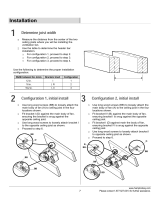
Planning Installation ................................................................3
Installation Options ..................................................................4
Tools required ..........................................................................4
Materials required ....................................................................4
Hardware Included ........................................................ 5
Package Contents ....................................................................5
Installation ..................................................................... 6
Care and Cleaning ........................................................ 9
Specifications .............................................................. 10
BPT18-34A-2 ..........................................................................10
BPT18-54A-1 ..........................................................................10
DIMENSIONS (BPT18-34A-2 & BPT18-54A-1) ........................10
Service Parts ............................................................... 11
BPT18-34A-2 SERVICEABLE PARTS .......................................11
BPT18-54A-1 SERVICEABLE PARTS .......................................12
Safety Information
1. This ventilation fan is approved for use over a bathtub or
shower when installed in a GFCI protected circuit. Do not
use unapproved fans over a bathtub or shower that does not
include a GFCI protected circuit.
2. Installation work must be carried out by a qualified person(s)
in accordance with all local and safety codes including the
rules for fire-rated construction.
3. To reduce the risk of fire, always vent fans to the exterior
and in compliance with local codes. Do not vent exhaust air
into spaces within walls, ceilings, attics, crawl spaces, or
garages.
4. Install ductwork in a straight line with minimal bends.
5. Use 120 V, 60 Hz for the electrical supply and properly
ground the unit. Follow all local safety and electrical codes.
6. Do not use this fan with any solid state control device; such
as a dimmer switch. Solid-state controls may cause
harmonic distortion, which can cause a motor humming
noise.
7. To reduce the risk of fire, electric shock or injury to persons,
observe the following:
Use this unit only in the manner intended by the
manufacturer. If you have questions, contact the
manufacturer.
Before servicing or cleaning the unit, switch the power
off at the service panel and lock the service
disconnecting means to prevent power from being
switched on accidentally. When the service
disconnecting means cannot be locked, securely fasten
a prominent warning device, such as a tag, to the
service panel.
8. Sufficient air is needed for proper combustion and
exhausting of gases through the flue (chimney) of fuel
burning equipment to prevent back drafting. Follow the
heating equipment manufacturer’s guideline and safety
standards such as those published by the National Fire
Protection Association (NFPA), and the American Society for
Heating, Refrigeration and Air Conditioning Engineers
(ASHRAE), and the local code authorities.
WARNING: Not suitable for use as a range hood or in
areas where hazardous or explosive vapors are present.
WARNING: FOR USE IN NON FIRE-RELATED
INSTALLATIONS ONLY.
WARNING: FOR USE IN ONE-AND-TWO FAMILY
DWELLINGS ONLY
WARNING: To reduce the risk of fire or electric shock, do
not use this fan with any solid-state speed control device.
CAUTION: Do not install in locations where the air
temperature will exceed 104°F (40°C).
CAUTION: For general ventilating use only. Do not use to
exhaust hazardous or explosive materials and vapors.
IMPORTANT: You may want to consult with a
professional electrician regarding the wiring of your
ventilation fan.
IMPORTANT: Exercise care to not damage existing
wiring when cutting or drilling into walls or ceilings.
NOTE: Make sure the duct work size is a minimum of the
discharge. Do not reduce. Reducing the duct size can
increase fan noise.
NOTE: Proper installation of insulation around and over
fan body to minimize building heat loss and gain.
3 HAMPTONBAY.COM
Please contact 1-855-HD-HAMPTON for further assistance.
Warranty
If this product fails due to a defect in materials or workmanship at any time during the first three years of ownership, the manufacturer will
replace it free of charge, postage-paid at their option. This warranty does not cover products which have been abused, altered, damaged,
misused, cut or worn. This warranty does not cover use in commercial applications. The manufacturer DISCLAIMS all other implied or
express warranties including all warranties of merchantability and/or fitness for a particular purpose. As some states do not allow
exclusions or limitations on an implied warranty, the above exclusions and limitations may not apply. This warranty gives you specific legal
rights, and you may have other rights that vary from state to state.
This warranty is limited to the replacement of defective parts only. Labor charges and/or damage incurred during installation, repair,
replacement as well as incidental and consequential damages connected with the above are excluded. Any damage to this product as a
result of neglect, misuse, accident, improper installation or use other than the purpose SHALL VOID THIS WARRANTY.
Contact the Customer Service Team at 1-855-HD-HAMPTON or visit www.hamptonbay.com.
Pre-installation
PLANNING INSTALLATION
When installing the ventilation fan in a new construction site, install the main body of the fan and duct work during the roughin
construction of the building. The grill should be installed after the finished ceiling is in place.
When installing in existing construction, use the dimensions on page 12 to determine the required hole size for the ceiling. The grill edges
should overlap the finished ceiling.
NOTE: If installing in existing construction, you must
have access to space above and below the installation
location.
This unit will operate most quietly and efficiently when located where the shortest possible duct run and minimum number of elbows will be
needed.
Do not install the ventilation fan in areas where the duct work will require configurations as shown in the following figure:
4
Pre-installation (continued)
INSTALLATION OPTIONS
We recommend installing the ventilation fan by securing the main body of the fan against one ceiling joist and using the header bars as
necessary for support of the adjoining joist.
There are multiple installation configurations possible for this ventilation fan. Not all configurations are shown. If your installation requires a
variation other than those shown, consult with a licensed contractor to determine the best installation for your project. If you are replacing
an existing fan, ensure that the new grill will adequately cover the existing opening.
TOOLS REQUIRED
Hammer
Safety
goggles
Phillips
screwdriver
Level
Electrical tape
Drill
MATERIALS REQUIRED
Duct vent
Duct
clamp
Duct tape
Duct piping
5 HAMPTONBAY.COM
Please contact 1-855-HD-HAMPTON for further assistance.
Pre-installation (continued)
HARDWARE INCLUDED
NOTE: Hardware not shown to actual size.
Part Description Quantity
A
A
Quick connect 3
BB Long wood screw (M4x30) 8
CC Short screw (M4x12) 2
DD Short screw (M4x8) 1
PACKAGE CONTENTS
Part Description
A
Fan body
B Grill
C Suspension bracket I
D Suspension bracket II
E Suspension bracket III
BB CC DDAA
C
D
E
A
B
6
Installation
1
Determining joist width
Measure the distance from the center of the two ceiling
joists where you will be installing the ventilation fan.
2
Joint installation under 10 ½ in.
3 a
Suspension bracket installation
Use four long wood screws (BB) to attach the main body of
the fan to the ceiling joists.
Ensure the main body is level and square to the joists.
Tighten all screws.
CAUTION: Do not mount the fan flush against the joist.
The flange should be flush with the ceiling board.
For ceiling joist installations under 20 in., insert suspension
bracket I (C) into the fan body (A). Proceed to step 3b.
For ceiling joist installations between 20 in. and 24 in., insert
suspension brackets I (C), II (D), and III (E). Proceed to step 4.
Use the screw (DD) to secure the suspension bracket (C) to the
fan body (A).
Use the screws (CC) to secure the suspension brackets (D and E)
to the fan body (A).
Suspension brackets I (C) and II (D) should be secured at the
same side joist.
NOTE: Sliding hanger bars are provided to allow for
accurate positioning of the main body between joists.
BB
BB
A
D
D
C
C
C
D
E
7 HAMPTONBAY.COM
Please contact 1-855-HD-HAMPTON for further assistance.
Installation (continued)
3 b
20 – 24 in. joist installation
4
Duct connection
Use long wood screws (BB) to loosely attach the main body of the
fan to one ceiling joist.
Extend the hanger bars to the opposite ceiling joist.
Secure the suspension brackets (C, D, and E) to the joist using long
wood screws (BB).
Ensure the main body is level and square to the joists.
Tighten all screws.
CAUTION: Do not mount the fan flush against the joist.
The flange should be flush with the ceiling board.
Install a circular duct (Q) to the outlet and secure it with
duct tape or clamps to the outlet.
Install the duct with a gradient of 1˚ ~ 2˚ to the outside.
BB
Q
8
Installation (continued)
5
Using quick connect
6
Connecting wiring from unit to
house
WARNING: Wiring must comply with all applicable
electrical codes. Turn OFF power before removing or
installing connectors.
WARNING: COPPER TO COPPER ONLY. Do not use on
Aluminum wire.
CAUTION: Accessory part AA (quick connect) should meet
installation instructions below.
NOTE: Connector is reusable on solid wires of the same
wire gage or smaller. Do not reuse connector on stranded
wires.
Strip the wires so half of the bare wire is showing.
Grip the wire firmly and push the stripped end of the wire
into the open port of connector (AA). Use only one stripped
end of the wire per port.
Verify the stripped end of the wire is fully inserted to the
back of the connector (AA).
NOTE: Important wire information. Maximum temperature
rating 105°C (221°). 600 volts maximum for building wire
and 1000 volts maximum in signs and lighting fixtures.
Flammability rating of the wires must meet UL94-V2. The
acceptable wire range includes: Solid: 12-20 AWG, Stranded:
12-16 AWG (≤19 STRAND); 18AWG (7 STRAND), Tin bonded:
14-18 AWG (≤19 STRAND).
WARNING: Make sure that the main power is off
WARNING: Failure to wire this product correctly could
result in electrical shock, fire hazards, or damage to the
product. Consult a licensed electrician if you are unsure of
your ability to correctly install wiring.
CAUTION: If your house wires do not match these colors,
determine what each house wire represents before
connecting. You may need to consult a licensed electrician to
determine this safely.
Connect house wires to ventilation fan wires.
Match colors as shown (black to black, white to white, and
green to green) using quick connects (AA) or wire nuts (not
provided).
Replace the junction box cover. Do not pinch the lead wires.
Product wires
House wires
AA
Motor
Junction Box
Automatic Terminal
House wires
Product wires
Capacitator
(black) to switch
(white) to neutral
(green) to ground
AA
9 HAMPTONBAY.COM
Please contact 1-855-HD-HAMPTON for further assistance.
Installation (continued)
7
Mounting the grill
Use the spring clips to pinch mount and insert the grill (B)
into the narrow rectangular slots inside of the fan housing
next to the fan motor.
Care and Cleaning
Before servicing or cleaning the unit, disconnect the power supply at the panel and lock to prevent the power from being turned
on. If the panel cannot be locked, clearly mark the panel with a warning tag to prevent the power from being turned on.
Remove the grill by squeezing the springs and pulling the grill down.
Wash and clean the grill in a sink and dry with a cloth.
Remove dust and dirt from the fan housing with a vacuum cleaner.
Dampen a cloth with dish detergent, wipe the fan housing and dry with a cloth.
Replace the grill.
To reduce the risk of fire, always vent fans to the exterior and in compliance with local codes. Do not vent exhaust air into spaces
within walls, ceilings, attics, crawl spaces, or garages.
Unplug or disconnect the appliance from the power supply before servicing.
CAUTION: Do not use solvents, thinner or harsh
chemicals for cleaning the fan..
CAUTION: Do not allow water to enter the motor
CAUTION: Do not immerse resin parts in water over 140°
F (60° C).
B
10
Specifications
BPT18-34A-2
Model No. BPT18-34
A
-2
Air direction 110 cfm
V
oltage 120
V
Hertz 60 HZ
Duct diameter 6 in. (15.24 cm)
Noise 0.8 Sone
Power consumption (Watts) 32 W
Speed 717 rpm
Air deliver at 0.1" WG 110 cfm
Weight 10.78 lbs. (4.9 kg)
BPT18-54A-1
Model No. BPT18-54
A
-1
Air direction 140 cfm
V
oltage 120
V
Hertz 60 HZ
Duct diameter 6 in. (15.24 cm)
Noise 1.0 Sone
Power consumption (Watts) 41 W
Speed 762 rpm
Air deliver at 0.1" WG 140 cfm
Weight 10.78 lbs. (4.9 kg)
DIMENSIONS (BPT18-34A-2 & BPT18-54A-1)
Ceiling opening - length 10.8 in. (27.4 cm)
Ceiling opening - width 10.5 in. (26.7 cm)
Ceiling opening - depth 8.5 in. (21.6 cm)
Housing dimension - length 10.2 in. (25.9 cm)
Housing dimension - width 10.2 in. (25.9 cm)
Housing dimension - depth 8.0 in. (20.30 cm)
Service Parts
BPT18-34A-2 SERVICEABLE PARTS
Part Number Description Quantity
HM0000004 Quick connectors 3
UB40403001 Long wood screws (M4x30) 8
UC40400802 Short screws (M4x12) 2
ABPTA05603 Grill and spring clip 1
ABPTA03406 Complete assembled fan and housing 1
ABPTAL05604 Complete suspension bracket 1
UC40401201 Short Screw (M4x8) 1
ABPTA03406
ABPTA05603
UC40400802UB40403001HM0000004
ABPTAL05604
UC40401201UC40400802
11 HAMPTONBAY.COM
Please contact 1-855-HD-HAMPTON for further assistance.
12
Service Parts (continued)
BPT18-54A-1 SERVICEABLE PARTS
Part Number Description Quantity
HM0000004 Quick connectors 3
UB40403001 Long wood screws (M4x30) 8
UC40400802 Short screws (M4x12) 2
ABPTA05603 Grill and spring clip 1
ABPTA05602 Complete assembled fan and housing 1
ABPTAL05604 Complete suspension bracket 1
UC40401201 Short Screw (M4x8) 1
ABPTA05602
UC40400802UB40403001HM0000004
ABPTA05603
ABPTAL05604
UC40401201UC40400802
Questions, problems, missing parts? Before returning to the store,
call Hampton Bay Customer Service
8 a.m. - 6 p.m., EST, Monday-Friday
1-855-HD-HAMPTON
HAMPTONBAY.COM
Retain this manual for future use.
20140808-B
13
  • Page 1 1
  • Page 2 2
  • Page 3 3
  • Page 4 4
  • Page 5 5
  • Page 6 6
  • Page 7 7
  • Page 8 8
  • Page 9 9
  • Page 10 10
  • Page 11 11
  • Page 12 12
  • Page 13 13
  • Page 14 14
  • Page 15 15
  • Page 16 16
  • Page 17 17
  • Page 18 18
  • Page 19 19
  • Page 20 20
  • Page 21 21
  • Page 22 22
  • Page 23 23
  • Page 24 24
  • Page 25 25
  • Page 26 26
  • Page 27 27
  • Page 28 28
  • Page 29 29
  • Page 30 30
  • Page 31 31
  • Page 32 32
  • Page 33 33
  • Page 34 34
  • Page 35 35
  • Page 36 36
  • Page 37 37
  • Page 38 38
  • Page 39 39

Hampton Bay BPT18-34A-2 Installation guide

Category
Barbecues & grills
Type
Installation guide
This manual is also suitable for

Ask a question and I''ll find the answer in the document

Finding information in a document is now easier with AI