13
Remote Control (continued)
Remote Control (continued)
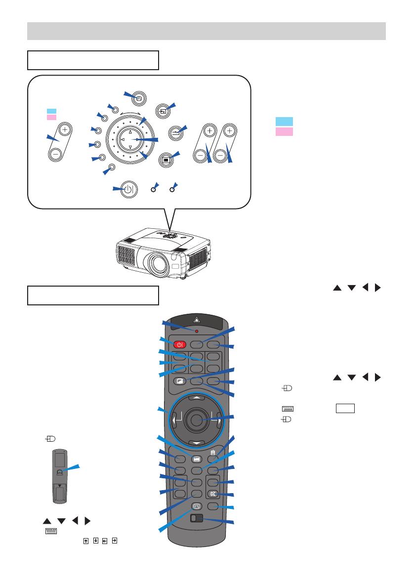
Operating The Remote Control
CAUTION • Do not disassemble the remote control.
• Do not place the remote control near the projector’s lens, fan, or vents.
• Do not drop or otherwise expose the remote control to physical impact.
•
Do not get the remote control wet or place it on wet objects on it. Doing so may result in malfunction.
• Remove the batteries from the remote control and store them in a safe place if you
won't be using the remote control for an extended period.
• Replace the batteries whenever the remote control starts to malfunction.
•
When strong light, such as direct sunlight or light from an extremely close range (such as from an
inverter fluorescent lamp), hits the projector's remote sensor, the remote control may cease to function.
Adjust the direction of the projector to keep light from directly hitting the projector's remote sensor.
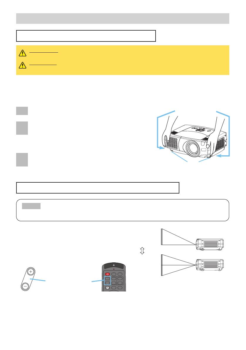
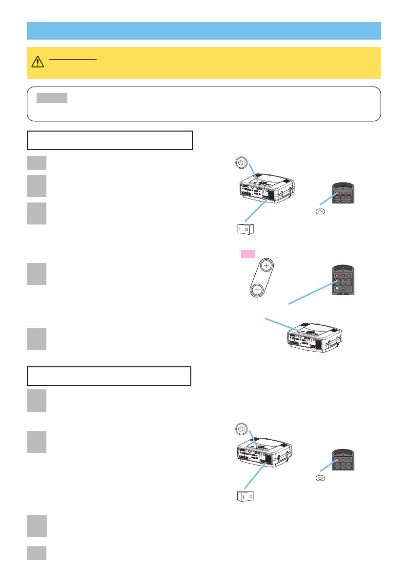
NOTE
•
The remote control works with the
projector’s remote sensor.
•
Front remote sensor is 3 meters with a 40
degree range (20 degrees to the left and
right of a remote sensor).
Rear remote sensor is 3 meters with a 40
degree range (20 degrees to the left and
right of a remote sensor).
•
Also a remote signal reflected in the screen etc.
may be available. If it is difficult to send a remote signal to the sensor directly, please try.
•
Since the remote control uses infrared light to send signals to the projector (Class1 LED), be sure to use the
remote control in an area free from obstacles that could block the remote control’s output signal to the projector.
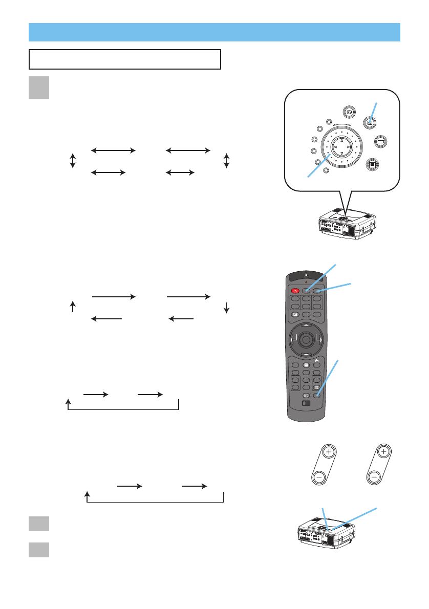
memo
You can use the remote control as a wired remote control, by connecting the REMOTE CONTROL
ports of the main unit and remote control via an audio cable (3.5 dia. stereo mini cable with plugs).
Set the ID number to the projector beforehand,
referring to the item “IR REMOTE ID” of the section
“OPTION Menu”.
memo
When the ALL is selected to the item “IR
REMOTE ID” of the OPTION menu, the projector is
controlled by a remote control irrespective of the
position of the ID CHANGE switch.
Slide the knob of the switch into the position of the
ID number of the projector you want to control.
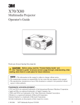
Using The Remote ID Feature
This is the function to properly use when you use two or
three same type projectors at the same time. This function
should be used combining a setup of a projector.
ID CHANGE
switch