45005-00-ENG

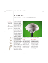
Trimble Outdoors 45005-00-ENG, AcutimeTM2000 Synchronization Kit, Part Number 45005-00-ENG User manual

  • Hello! I am an AI chatbot trained to assist you with the Trimble Outdoors 45005-00-ENG User manual. I’ve already reviewed the document and can help you find the information you need or explain it in simple terms. Just ask your questions, and providing more details will help me assist you more effectively!
F
Part Number 45005-00-ENG
Revision A
April 2001
Acutime
2000
Synchronization Kit
User Guide
Corporate Office
Trimble Navigation Limited
Timing and Synchronization Group
645 North Mary Avenue
Post Office Box 3642
Sunnyvale, CA 94088-3642
U.S.A.
Phone: +1-408-481-8940, 1-800-545-7762
Fax: +1-408-481-7744
www.trimble.com
Support Offices
Trimble Navigation Europe Limited
Trimble House, Meridian Office Park
Osborn Way, Hook
Hampshire RG27 9HX
ENGLAND
+44-1256-760-150
Fax: +44-1256-760-148
Voicemail: +44-1256-761-130
Trimble Navigation Singapore PTE Limited
79 Anson Road
# 05-02
Singapore 079906
SINGAPORE
+65-325-5668
Fax: +65-225-9989
Voicemail: +65-325-5668
Trimble Japan K.K.
Sumitomo Hamamatsu-cho, Building 10F
1-18-16 Hamamatsu-cho Minato-ku
Tokyo 105
JAPAN
+81-3-5472-0880
Fax: +81-3-5472-2326
Trimble Navigation Australia Pty Limited
P.O. Box 769
Spring Hill QLD 4004
AUSTRALIA
+61-7-3216-0044
Fax: +61-7-3216-0088
Copyright and Trademarks
© 2001, Trimble Navigation Limited. All rights
reserved.
No part of this manual may be
copied, reproduced, translated, or reduced to
any electronic medium or machine-readable
form for any use other than with the
Acutime™ 2000 GPS Smart Antenna, or
Acutime 2000 Synchronization Kit.
The Sextant logo with Trimble is a trademark of
Trimble Navigation Limited, registered in the
United States Patent and Trademark Office.
The Globe & Triangle logo, Trimble, and Acutime
are trademarks of Trimble Navigation Limited.
All other trademarks are the property of their
respective owners.
Release Notice
This is the
April 2001 release (Revision A) of
the
Acutime 2000 Synchronization Kit
User Guide
, part number 45005-00-ENG. It
applies to the
Acutime ™ 2000 Synchronization
Kit software.
The following limited warranties give you specific
legal rights. You may have others, which vary
from state/jurisdiction to state/jurisdiction.
Hardware Limited Warranty
Trimble warrants that this Trimble hardware
product (the “Product”) shall be free from defects
in materials and workmanship and will
substantially conform to Trimble’s applicable
published specifications for the Product for a
period of one (1) year, starting from the date of
delivery. The warranty set forth in this paragraph
shall not apply to software/firmware products.
Software and Firmware License, Limited
Warranty
This Trimble software and/or firmware product
(the Software) is licensed and not sold. Its use is
governed by the provisions of the applicable End
User License Agreement (EULA), if any,
included with the Software. In the absence of a
separate EULA included with the Software
providing different limited warranty terms,
exclusions, and limitations, the following terms
and conditions shall apply. Trimble warrants that
this Trimble Software product will substantially
conform to Trimbles applicable published
specifications for the Software for a period of
ninety (90) days, starting from the date of
delivery.
Warranty Remedies
Trimble's sole liability and your exclusive remedy
under the warranties set forth above shall be, at
Trimbles option, to repair or replace any Product
or Software that fails to conform to such warranty
(Nonconforming Product), or refund the
purchase price paid by you for any such
Nonconforming Product, upon your return of any
Nonconforming Product to Trimble in accordance
with Trimbles standard return material
authorization procedures.
Warranty Exclusions and Disclaimer
These warranties shall be applied only in the event
and to the extent that: (i) the Products and
Software are properly and correctly installed,
configured, interfaced, maintained, stored, and
operated in accordance with Trimbles relevant
operator's manual and specifications, and; (ii) the
Products and Software are not modified or
misused. The preceding warranties shall not apply
to, and Trimble shall not be responsible for defects
or performance problems resulting from (i) the
combination or utilization of the Product or
Software with products, information, data,
systems or devices not made, supplied or specified
by Trimble; (ii) the operation of the Product or
Software under any specification other than, or in
addition to, Trimble's standard specifications for
its products; (iii) the unauthorized modification or
use of the Product or Software; (iv) damage
caused by accident, lightning or other electrical
discharge, fresh or salt water immersion or spray;
or (v) normal wear and tear on consumable parts
(e.g., batteries).
THE WARRANTIES ABOVE STATE TRIMBLE'S
ENTIRE LIABILITY, AND YOUR EXCLUSIVE
REMEDIES, RELATING TO PERFORMANCE OF
THE PRODUCTS AND SOFTWARE. EXCEPT AS
OTHERWISE EXPRESSLY PROVIDED HEREIN,
THE PRODUCTS, SOFTWARE, AND
ACCOMPANYING DOCUMENTATION AND
MATERIALS ARE PROVIDED AS-IS AND
WITHOUT EXPRESS OR IMPLIED WARRANTY
OF ANY KIND BY EITHER TRIMBLE
NAVIGATION LIMITED OR ANYONE WHO HAS
BEEN INVOLVED IN ITS CREATION,
PRODUCTION, INSTALLATION, OR
DISTRIBUTION, INCLUDING, BUT NOT LIMITED
TO, THE IMPLIED WARRANTIES OF
MERCHANTABILITY AND FITNESS FOR A
PARTICULAR PURPOSE, TITLE, AND
NONINFRINGEMENT. THE STATED EXPRESS
WARRANTIES ARE IN LIEU OF ALL
OBLIGATIONS OR LIABILITIES ON THE PART
OF TRIMBLE ARISING OUT OF, OR IN
CONNECTION WITH, ANY PRODUCTS OR
SOFTWARE. SOME STATES AND
JURISDICTIONS DO NOT ALLOW LIMITATIONS
ON DURATION OR THE EXCLUSION OF AN
IMPLIED WARRANTY, SO THE ABOVE
LIMITATION MAY NOT APPLY TO YOU.
TRIMBLE NAVIGATION LIMITED IS NOT
RESPONSIBLE FOR THE OPERATION OR
FAILURE OF OPERATION OF GPS SATELLITES
OR THE AVAILABILITY OF GPS SATELLITE
SIGNALS.
Limitation of Liability
TRIMBLES ENTIRE LIABILITY UNDER ANY
PROVISION HEREIN SHALL BE LIMITED TO
THE GREATER OF THE AMOUNT PAID BY YOU
FOR THE PRODUCT OR SOFTWARE LICENSE OR
U.S.$25.00. TO THE MAXIMUM EXTENT
PERMITTED BY APPLICABLE LAW, IN NO
EVENT SHALL TRIMBLE OR ITS SUPPLIERS BE
LIABLE FOR ANY INDIRECT, SPECIAL,
INCIDENTAL, OR CONSEQUENTIAL DAMAGES
WHATSOEVER UNDER ANY CIRCUMSTANCE
OR LEGAL THEORY RELATING IN ANY WAY TO
THE PRODUCTS, SOFTWARE, AND
ACCOMPANYING DOCUMENTATION AND
MATERIALS, (INCLUDING, WITHOUT
LIMITATION, DAMAGES FOR LOSS OF
BUSINESS PROFITS, BUSINESS INTERRUPTION,
LOSS OF BUSINESS INFORMATION, OR ANY
OTHER PECUNIARY LOSS), REGARDLESS OF
WHETHER TRIMBLE HAS BEEN ADVISED OF
THE POSSIBILITY OF ANY SUCH LOSS AND
REGARDLESS OF THE COURSE OF DEALING
WHICH DEVELOPS OR HAS DEVELOPED
BETWEEN YOU AND TRIMBLE. BECAUSE SOME
STATES AND JURISDICTIONS DO NOT ALLOW
THE EXCLUSION OR LIMITATION OF LIABILITY
FOR CONSEQUENTIAL OR INCIDENTAL
DAMAGES, THE ABOVE LIMITATION MAY NOT
APPLY TO YOU.
Notices
Class B Statement Notice to Users. This
equipment has been tested and found to comply
with the limits for a Class B digital device,
pursuant to Part 15 of the FCC rules. These limits
are designed to provide reasonable protection
against harmful interference in a residential
installation. This equipment generates, uses, and
can radiate radio frequency energy and, if not
installed and used in accordance with the
instructions, may cause harmful interference to
radio communication. However, there is no
guarantee that interference will not occur in a
particular installation. If this equipment does
cause harmful interference to radio or television
reception, which can be determined by turning the
equipment off and on, the user is encouraged to
try to correct the interference by one or more of
the following measures:
Reorient or relocate the receiving antenna.
Increase the separation between the equipment
and the receiver.
Connect the equipment into an outlet on a
circuit different from that to which the receiver
is connected.
Consult the dealer or an experienced radio/TV
technician for help.
Changes and modifications not expressly
approved by the manufacturer or registrant of this
equipment can void your authority to operate this
equipment under Federal Communications
Commission rules.
European Community (CE) Directive
Conformance Statement
The Acutime 2000 GPS Smart Antenna conforms
with the essential requirements of the EMC
Directive 89/336/EEC. A Declaration of
Conformity indicating the requirements met has
been signed at Trimble Navigation Limited, 645
North Mary Avenue, Sunnyvale, CA 94086, USA.
Acutime 2000 Synchronization Kit User Guide v
Contents
About This Manual
Scope and Audience . . . . . . . . . . . . . . . . . . . . . . . . xix
Organization . . . . . . . . . . . . . . . . . . . . . . . . . . . . xx
Reader Feedback . . . . . . . . . . . . . . . . . . . . . . . . . . xxi
Related Information . . . . . . . . . . . . . . . . . . . . . . . . xxii
Update Notes . . . . . . . . . . . . . . . . . . . . . . .xxii
World Wide Web (WWW) Site . . . . . . . . . . . . . .xxii
Technical Assistance. . . . . . . . . . . . . . . . . . . .xxiii
Abbreviations. . . . . . . . . . . . . . . . . . . . . . . . . . . . xxiii
Document Conventions. . . . . . . . . . . . . . . . . . . . . . . xxiii
Cautions and Notes . . . . . . . . . . . . . . . . . . . . . . . . . xxiv
1 Introduction
1.1 Overview . . . . . . . . . . . . . . . . . . . . . . . . . . . . . . 1-1
1.2 Acutime 2000 GPS Smart Antenna Features. . . . . . . . . . . . 1-2
1.3 Starter Kit. . . . . . . . . . . . . . . . . . . . . . . . . . . . . . 1-4
2 Getting Started
2.1 Connecting the Smart Antenna. . . . . . . . . . . . . . . . . . . 2-2
2.2 Connecting the Computer and Power Source . . . . . . . . . . . 2-3
2.3 Communicating with the Acutime 2000 . . . . . . . . . . . . . . 2-4
vi Acutime 2000 Synchronization Kit User Guide
Contents
3 Acutime 2000 Installation
3.1 Choosing a Location . . . . . . . . . . . . . . . . . . . . . . . . 3-2
3.2 Mounting the Smart Antenna. . . . . . . . . . . . . . . . . . . . 3-4
3.3 Routing and Securing the Interface Cable . . . . . . . . . . . . . 3-5
3.4 Connecting the Host System . . . . . . . . . . . . . . . . . . . . 3-6
4 Acutime 2000 Connections
4.1 Interface and Power Connections. . . . . . . . . . . . . . . . . . 4-2
4.2 Interface Cables and Connectors . . . . . . . . . . . . . . . . . . 4-4
4.2.1 Pin-Outs . . . . . . . . . . . . . . . . . . . . . . . . . .4-5
4.3 Connection Instructions . . . . . . . . . . . . . . . . . . . . . . 4-7
4.3.1 Power Connection (Red and Black Wires) . . . . . . . .4-7
4.3.2 Timing Pulse Connections. . . . . . . . . . . . . . . . .4-7
4.3.3 Serial Port Connections . . . . . . . . . . . . . . . . . .4-8
4.3.4 Event Input. . . . . . . . . . . . . . . . . . . . . . . . .4-9
5 System Operation
5.1 Start-Up. . . . . . . . . . . . . . . . . . . . . . . . . . . . . . . 5-1
5.2 Automatic Operation . . . . . . . . . . . . . . . . . . . . . . . . 5-2
5.2.1 Satellite Masks. . . . . . . . . . . . . . . . . . . . . . .5-2
5.2.2 Tracking Modes . . . . . . . . . . . . . . . . . . . . . .5-4
5.2.3 PPS Output Options . . . . . . . . . . . . . . . . . . . .5-6
5.2.4 PPS Quantization Error . . . . . . . . . . . . . . . . . .5-7
5.2.5 External Event Input. . . . . . . . . . . . . . . . . . . .5-9
5.2.6 Cable Delay Compensation . . . . . . . . . . . . . . . .5-9
5.3 Serial Data Communication . . . . . . . . . . . . . . . . . . . . 5-10
5.3.1 Port B . . . . . . . . . . . . . . . . . . . . . . . . . . .5-10
5.3.2 Port A (Timing) . . . . . . . . . . . . . . . . . . . . . .5-10
5.4 GPS Timing . . . . . . . . . . . . . . . . . . . . . . . . . . . . 5-12
5.4.1 Timing Operation . . . . . . . . . . . . . . . . . . . . .5-13
Acutime 2000 Synchronization Kit User Guide vii
Contents
5.5 Using the Acutime 2000 in Mobile Applications . . . . . . . . . 5-15
5.6 Customizing Acutime 2000 Operations . . . . . . . . . . . . . . 5-16
6 NTP Software Installation and Configuration
6.1 Network Time Protocol. . . . . . . . . . . . . . . . . . . . . . . 6-1
6.1.1 NTP Time Servers . . . . . . . . . . . . . . . . . . . . .6-2
6.2 Software Sources and Compatibility . . . . . . . . . . . . . . . . 6-3
6.2.1 Installation Support . . . . . . . . . . . . . . . . . . . .6-4
6.3 Pre-Installation Check List . . . . . . . . . . . . . . . . . . . . . 6-4
6.3.1 GPS Preparation . . . . . . . . . . . . . . . . . . . . . .6-5
6.3.2 Host System Preparation . . . . . . . . . . . . . . . . .6-6
6.3.3 Operating System Specific Information . . . . . . . . . .6-7
6.4 Time Transfer Cable Connection. . . . . . . . . . . . . . . . . . 6-8
6.4.1 Optional Connections . . . . . . . . . . . . . . . . . . .6-9
6.5 NTP Software Installation . . . . . . . . . . . . . . . . . . . . . 6-10
6.5.1 NTP Configuration File . . . . . . . . . . . . . . . . . .6-11
6.5.2 Acutime Configuration . . . . . . . . . . . . . . . . . .6-12
6.5.3 Network Server Selection . . . . . . . . . . . . . . . . .6-13
6.5.4 Additional Configuration Information. . . . . . . . . . .6-14
6.6 Windows NT Installation. . . . . . . . . . . . . . . . . . . . . . 6-15
6.6.1 Automatic Installation . . . . . . . . . . . . . . . . . . .6-16
6.6.2 Manual Installation . . . . . . . . . . . . . . . . . . . .6-17
6.6.3 Starting the Service . . . . . . . . . . . . . . . . . . . .6-23
6.7 UNIX Installation. . . . . . . . . . . . . . . . . . . . . . . . . . 6-24
6.7.1 Create the Configuration File . . . . . . . . . . . . . . .6-25
6.7.2 Set Up Device Links. . . . . . . . . . . . . . . . . . . .6-26
6.7.3 Hardware Configuration. . . . . . . . . . . . . . . . . .6-28
6.7.4 Copying Executable Files . . . . . . . . . . . . . . . . .6-29
6.7.5 System Initialization. . . . . . . . . . . . . . . . . . . .6-30
6.7.6 Start NTP . . . . . . . . . . . . . . . . . . . . . . . . .6-31
viii Acutime 2000 Synchronization Kit User Guide
Contents
6.8 Monitoring NTP . . . . . . . . . . . . . . . . . . . . . . . . . . 6-31
6.8.1 NTP Events on Windows NT . . . . . . . . . . . . . . .6-32
6.8.2 UNIX System Log Files . . . . . . . . . . . . . . . . . .6-34
6.8.3 NTPQ The NTP Query Utility . . . . . . . . . . . . .6-35
A Trimble Standard Interface Protocol
A.1 Interface Scope . . . . . . . . . . . . . . . . . . . . . . . . . . . A-1
A.1.1 Packet Structure . . . . . . . . . . . . . . . . . . . . . .A-2
A.2 Physical Interface Characteristics . . . . . . . . . . . . . . . . . A-3
A.2.1 Nomenclature . . . . . . . . . . . . . . . . . . . . . . .A-4
A.2.2 Protocol Capabilities. . . . . . . . . . . . . . . . . . . .A-4
A.2.3 Event Input. . . . . . . . . . . . . . . . . . . . . . . . .A-6
A.3 Packets Output at Power-Up . . . . . . . . . . . . . . . . . . . . A-6
A.4 Receiver Warm Start . . . . . . . . . . . . . . . . . . . . . . . . A-7
A.5 Default Background Packets for Acutime 2000 . . . . . . . . . . A-8
A.6 Default Automatic Position and Velocity Reports
for Acutime 2000 . . . . . . . . . . . . . . . . . . . . . . . . . A-9
A.7 Automatic Primary and Supplemental Timing Reports
for ACE UTC . . . . . . . . . . . . . . . . . . . . . . . . . . . A-9
A.8 Low-Latency Timing Packets . . . . . . . . . . . . . . . . . . . A-10
A.9 Event Packets. . . . . . . . . . . . . . . . . . . . . . . . . . . . A-11
A.10 Satellite Data Packets. . . . . . . . . . . . . . . . . . . . . . . . A-11
A.11 Customizing Receiver Operations . . . . . . . . . . . . . . . . . A-12
A.12 Command Packets Sent to the Receiver . . . . . . . . . . . . . . A-14
A.13 Report Packets Sent by the GPS Receiver to the User . . . . . . . A-16
A.14 Packet Structure . . . . . . . . . . . . . . . . . . . . . . . . . . A-19
A.15 Packet Descriptions. . . . . . . . . . . . . . . . . . . . . . . . . A-20
A.16 Custom OEM Packets . . . . . . . . . . . . . . . . . . . . . . . A-85
A.17 TSIP Superpackets . . . . . . . . . . . . . . . . . . . . . . . . . A-85
A.18 Datums . . . . . . . . . . . . . . . . . . . . . . . . . . . . . . . A-126
A.19 Sample TSIP Routines . . . . . . . . . . . . . . . . . . . . . . . A-134
Acutime 2000 Synchronization Kit User Guide ix
Contents
B Timing Receiver Monitor
B.1 Start-Up. . . . . . . . . . . . . . . . . . . . . . . . . . . . . . . B-1
B.2 Main screen. . . . . . . . . . . . . . . . . . . . . . . . . . . . . B-2
C NMEA 0183
C.1 The NMEA 0183 Communication Interface . . . . . . . . . . . . C-2
C.2 NMEA 0183 Message Format . . . . . . . . . . . . . . . . . . . C-2
C.3 NMEA 0183 Message Options. . . . . . . . . . . . . . . . . . . C-4
C.4 NMEA 0183 Message Formats. . . . . . . . . . . . . . . . . . . C-5
C.4.1 GGA GPS Fix Data . . . . . . . . . . . . . . . . . . .C-5
C.4.2 GLL Geographic Position Latitude/Longitude . . . .C-6
C.4.3 GSA GPS DOP and Active Satellites . . . . . . . . . .C-7
C.4.4 GSV GPS Satellites in View. . . . . . . . . . . . . . .C-8
C.4.5 RMC Recommended Minimum Specific
GPS/Transit Data . . . . . . . . . . . . . . . . . . . . .C-9
C.4.6 VTG Track Made Good and Ground Speed. . . . . . .C-10
C.4.7 ZDA Time & Date. . . . . . . . . . . . . . . . . . . .C-11
D Specifications and Drawings
D.1 Acutime 2000 GPS Smart Antenna Specifications. . . . . . . . . D-1
D.2 Acutime 2000 Standard Interface Cable Diagram . . . . . . . . . D-5
E NTP Diagnostics and Debugging
E.1 Diagnostics and Debugging . . . . . . . . . . . . . . . . . . . . E-1
E.1.1 System Log Entries . . . . . . . . . . . . . . . . . . . .E-1
E.1.2 Error Log Entries . . . . . . . . . . . . . . . . . . . . .E-3
E.2 Running NTP in Debug Mode . . . . . . . . . . . . . . . . . . . E-8
E.2.1 Debug Mode Not Available . . . . . . . . . . . . . . . .E-9
E.2.2 NTP Startup and Acutime Poll . . . . . . . . . . . . . .E-9
E.2.3 Acutime is not Responding . . . . . . . . . . . . . . . .E-11
x Acutime 2000 Synchronization Kit User Guide
Contents
E.2.4 Running NTP with Event Polling Disabled . . . . . . . .E-12
E.2.5 Incorrect Port and Bad Data . . . . . . . . . . . . . . . .E-15
E.2.6 Serial Port is Unavailable . . . . . . . . . . . . . . . . .E-16
E.3 Compiling the NTP Distribution . . . . . . . . . . . . . . . . . . E-17
E.4 Windows NT Administration. . . . . . . . . . . . . . . . . . . . E-21
E.4.1 Controlling the NTP Service . . . . . . . . . . . . . . .E-21
E.4.2 Removing the NTP Service . . . . . . . . . . . . . . . .E-21
E.5 Additional Information . . . . . . . . . . . . . . . . . . . . . . . E-23
F Theory of Operation
F.1 GPS Satellite Message . . . . . . . . . . . . . . . . . . . . . . . F-2
F.2 Satellite Acquisition and Time to First Fix. . . . . . . . . . . . . F-3
F.2.1 Cold Start . . . . . . . . . . . . . . . . . . . . . . . . .F-3
F.2.2 Warm Start. . . . . . . . . . . . . . . . . . . . . . . . .F-4
F.2.3 "Garage Search" Strategy . . . . . . . . . . . . . . . . .F-5
F.2.4 Hot Start . . . . . . . . . . . . . . . . . . . . . . . . . .F-5
F.3 Position Accuracy . . . . . . . . . . . . . . . . . . . . . . . . . F-6
F.3.1 Selective Availability (S/A) . . . . . . . . . . . . . . . .F-6
F.4 Coordinate Systems. . . . . . . . . . . . . . . . . . . . . . . . . F-7
F.4.1 TSIP . . . . . . . . . . . . . . . . . . . . . . . . . . . .F-7
F.4.2 NMEA 0183 . . . . . . . . . . . . . . . . . . . . . . . .F-7
F.5 Performance Characteristics . . . . . . . . . . . . . . . . . . . . F-8
F.5.1 Update Rate . . . . . . . . . . . . . . . . . . . . . . . .F-8
F.5.2 Dynamic Limits . . . . . . . . . . . . . . . . . . . . . .F-8
F.5.3 Re-Acquisition. . . . . . . . . . . . . . . . . . . . . . .F-8
F.6 System Architecture . . . . . . . . . . . . . . . . . . . . . . . . F-10
Glossary
Index
Acutime 2000 Synchronization Kit User Guide xi
List of Figures
Figure 1-1 Acutime 2000 GPS Smart Antenna Enclosure . . . . . . . 1-3
Figure 2-1 Connection Diagram . . . . . . . . . . . . . . . . . 2-3
Figure 3-1 Mounted Antenna . . . . . . . . . . . . . . . . . . 3-2
Figure 4-1 Acutime 2000 Interface Connector . . . . . . . . . . . 4-2
Figure 4-2 Acutime 2000 12-pin Connector format. . . . . . . . . . 4-3
Figure 5-1 PPS Quantization Error . . . . . . . . . . . . . . . . 5-7
Figure 5-2 Removing the Quantization Error from the PPS Output . . . 5-8
Figure 6-1 Time Transfer Connection Diagram . . . . . . . . . . . 6-8
Figure 6-2 NTP Configuration File . . . . . . . . . . . . . . . . 6-11
Figure 6-3 Disabling Serial Port Services Using an Administrative Tool . 6-28
Figure 6-4 Sample UNIX Log Entries . . . . . . . . . . . . . . . 6-34
Figure D-1 Acutime 2000 Standard Interface Cable. . . . . . . . . . D-5
Figure D-2 NTP Interface Cable . . . . . . . . . . . . . . . . . D-6
Figure F-1 Acutime 2000 Block Diagram (RS-232 Version) . . . . . . F-11
Figure F-2 Acutime 2000 Block Diagram (RS-422 Version) . . . . . . F-11
xii Acutime 2000 Synchronization Kit User Guide
List of Figures
Acutime 2000 Synchronization Kit User Guide xiii
List of Tables
Table 4-1 Mating Connectors . . . . . . . . . . . . . . . . . . . . . . . 4-4
Table 4-2 Acutime 2000 RS-422 Cable Pin-Out . . . . . . . . . . . . . 4-5
Table 4-3 Acutime 2000 RS-232 Cable Pin-Out . . . . . . . . . . . . . 4-6
Table 5-1 Default Satellite Mask Settings. . . . . . . . . . . . . . . . . 5-2
Table 5-2 Receiver Configuration (segment 2) . . . . . . . . . . . . . . 5-17
Table 5-3 OEM Configuration (segment 3). . . . . . . . . . . . . . . . 5-17
Table 5-4 Port A and B Configuration (segment 4). . . . . . . . . . . . 5-18
Table 5-5 PPS Configuration (segment 5). . . . . . . . . . . . . . . . . 5-18
Table 5-6 Position Information (segment 6) . . . . . . . . . . . . . . . 5-18
Table 5-7 Self-Survey Configuration (segment 7) . . . . . . . . . . . . 5-19
Table 5-8 NMEA Configuration (segment 8) . . . . . . . . . . . . . . . 5-19
Table 5-9 UTC Information (segment 11) . . . . . . . . . . . . . . . . 5-19
Table 6-1 System Serial Ports and Symbolic Link Names . . . . . . . . 6-27
Table A-1 Ace UTC Port Translation Table. . . . . . . . . . . . . . . . A-4
Table A-2 Acutime 2000 Port Translation Table . . . . . . . . . . . . . A-4
Table A-3 Secondary Port Features (Acutime 2000) . . . . . . . . . . . A-5
Table A-4 Secondary Port Features (Ace UTC). . . . . . . . . . . . . . A-6
Table A-5 Event Packets. . . . . . . . . . . . . . . . . . . . . . . . . . A-6
Table A-6 Packets Output at Power-Up . . . . . . . . . . . . . . . . . . A-7
Table A-7 Receiver Warm Start Commands . . . . . . . . . . . . . . . A-7
Table A-8 Background Packets . . . . . . . . . . . . . . . . . . . . . . A-8
Table A-9 Automatic position and Velocity Reports . . . . . . . . . . . A-9
Table A-10 Low-Latency Timing Packets . . . . . . . . . . . . . . . . . A-10
xiv Acutime 2000 Synchronization Kit User Guide
List of Tables
Table A-11 Satellite Data Packets. . . . . . . . . . . . . . . . . . . . . . A-11
Table A-12 Customizing Receiver Operations . . . . . . . . . . . . . . . A-12
Table A-13 Advanced Packets . . . . . . . . . . . . . . . . . . . . . . . A-13
Table A-14 Command Packets Sent to the Receiver . . . . . . . . . . . . A-14
Table A-15 Report Packets Sent by GPS Receiver to User. . . . . . . . . A-16
Table A-16 Command Packet 1D - Clear Oscillator Offset. . . . . . . . . A-20
Table A-17 Command Packet 1D - Set Oscillator Offset. . . . . . . . . . A-20
Table A-18 Command Packet 1E . . . . . . . . . . . . . . . . . . . . . . A-21
Table A-19 Command Packet 23 . . . . . . . . . . . . . . . . . . . . . . A-22
Table A-20 Command Packet 2B . . . . . . . . . . . . . . . . . . . . . . A-26
Table A-21 Command Packet 2E . . . . . . . . . . . . . . . . . . . . . . A-27
Table A-22 Command Packet 35 . . . . . . . . . . . . . . . . . . . . . . A-31
Table A-23 Command Packet 38 . . . . . . . . . . . . . . . . . . . . . . A-36
Table A-24 Command Packet 39 . . . . . . . . . . . . . . . . . . . . . . A-37
Table A-25 Command Packet 3A . . . . . . . . . . . . . . . . . . . . . . A-38
Table A-26 Command Packet 3B . . . . . . . . . . . . . . . . . . . . . . A-38
Table A-27 Command Packet 3C . . . . . . . . . . . . . . . . . . . . . . A-39
Table A-28 Command Packet 3F-11 . . . . . . . . . . . . . . . . . . . . A-40
Table A-29 Report Packet 40 . . . . . . . . . . . . . . . . . . . . . . . . A-40
Table A-30 Report Packet 41 . . . . . . . . . . . . . . . . . . . . . . . . A-41
Table A-31 Relationship Between Packet 41 and Packet 46 . . . . . . . . A-42
Table A-32 Report Packet 42 . . . . . . . . . . . . . . . . . . . . . . . . A-43
Table A-33 Report Packet 43 . . . . . . . . . . . . . . . . . . . . . . . . A-44
Table A-34 Report Packet 45 . . . . . . . . . . . . . . . . . . . . . . . . A-45
Table A-35 Report Packet 46 . . . . . . . . . . . . . . . . . . . . . . . . A-46
Table A-36 Report Packet 46 . . . . . . . . . . . . . . . . . . . . . . . . A-47
Table A-37 Report Packet 47 . . . . . . . . . . . . . . . . . . . . . . . . A-48
Table A-38 Report Packet 49 . . . . . . . . . . . . . . . . . . . . . . . . A-49
Table A-39 Report Packet 4A Report Reference Altitude . . . . . . . . A-49
Table A-40 Report Packet 4A Report Single-Precision LLA Position . . A-50
Acutime 2000 Synchronization Kit User Guide xv
List of Tables
Table A-41 Report Packet 4B . . . . . . . . . . . . . . . . . . . . . . . . A-51
Table A-42 Byte 1 Bit Encoding Status 1. . . . . . . . . . . . . . . . . A-51
Table A-43 Report Packet 4C . . . . . . . . . . . . . . . . . . . . . . . . A-52
Table A-44 Report Packet 4E . . . . . . . . . . . . . . . . . . . . . . . . A-53
Table A-45 Report UTC Parameters . . . . . . . . . . . . . . . . . . . . A-54
Table A-46 Report Packet 54 . . . . . . . . . . . . . . . . . . . . . . . . A-55
Table A-47 0x56 Velocity Fix, East-North-Up (ENU) Report . . . . . . A-56
Table A-48 Report Packet 57 . . . . . . . . . . . . . . . . . . . . . . . . A-57
Table A-49 Report Packet 58 . . . . . . . . . . . . . . . . . . . . . . . . A-58
Table A-50 Report Packet 58 ALMANAC Data Report . . . . . . . . . A-59
Table A-51 Report Packet 58 ALMANAC HEALTH Data Report. . . . A-60
Table A-52 Report Packet 58 IONOSPHERE Data Report. . . . . . . . A-60
Table A-53 Report Packet 58 UTC Data Report . . . . . . . . . . . . . A-61
Table A-54 Report Packet 58 EPHEMERIS Data Report . . . . . . . . A-61
Table A-55 Report Packet 59 . . . . . . . . . . . . . . . . . . . . . . . . A-63
Table A-56 Report Packet 5A. . . . . . . . . . . . . . . . . . . . . . . . A-64
Table A-57 Report Packet 5B . . . . . . . . . . . . . . . . . . . . . . . . A-67
Table A-58 Report Packet 5C . . . . . . . . . . . . . . . . . . . . . . . . A-68
Table A-59 Report Packet 5F-11 EEPROM Segment Status Report . . . A-70
Table A-60 Report Packet 0x60 Data Formats . . . . . . . . . . . . . . . A-71
Table A-61 Report Packet 0x60 Data Formats for Health and Power . . . A-72
Table A-62 Command Packet 0x61 Data Formats . . . . . . . . . . . . . A-73
Table A-63 Report Packet 6D. . . . . . . . . . . . . . . . . . . . . . . . A-74
Table A-64 Command Packet 7A . . . . . . . . . . . . . . . . . . . . . . A-75
Table A-65 Report Packet 83 . . . . . . . . . . . . . . . . . . . . . . . . A-76
Table A-66 Report Packet 84 . . . . . . . . . . . . . . . . . . . . . . . . A-77
Table A-67 Survey State Configurations . . . . . . . . . . . . . . . . . . A-78
Table A-68 Vaild GPS Configuration Settings . . . . . . . . . . . . . . . A-79
Table A-69 Command Packet BB. . . . . . . . . . . . . . . . . . . . . . A-81
Table A-70 Command Packet BC. . . . . . . . . . . . . . . . . . . . . . A-83
xvi Acutime 2000 Synchronization Kit User Guide
List of Tables
Table A-71 Command Packet 8E-14 . . . . . . . . . . . . . . . . . . . . A-87
Table A-72 Command Packet 8E-14 . . . . . . . . . . . . . . . . . . . . A-88
Table A-73 Command Packet 8E-20 . . . . . . . . . . . . . . . . . . . . A-89
Table A-74 Command Packet 0x8E-45 . . . . . . . . . . . . . . . . . . . A-90
Table A-75 Command Packet 8E-4A . . . . . . . . . . . . . . . . . . . . A-91
Table A-76 Command Packet 8E-4D . . . . . . . . . . . . . . . . . . . . A-92
Table A-77 Command Packet 8E-4D - Packets Affected By Bits . . . . . A-93
Table A-78 Command Packet 0x8E-4E. . . . . . . . . . . . . . . . . . . A-95
Table A-79 Command Packet 0x8E-4F. . . . . . . . . . . . . . . . . . . A-95
Table A-80 Command Packet 8E-A5 . . . . . . . . . . . . . . . . . . . . A-97
Table A-81 Command Packet 8E-A6 . . . . . . . . . . . . . . . . . . . . A-98
Table A-82 Command Packet 8E-A9 Data Format <<segment 7>> . . . . A-99
Table A-83 Command Packet 8E-AB. . . . . . . . . . . . . . . . . . . . A-100
Table A-84 Command Packet 8E-AC. . . . . . . . . . . . . . . . . . . . A-101
Table A-85 Report Packet 8F-0B . . . . . . . . . . . . . . . . . . . . . . A-103
Table A-86 Report Packet 8F-14 . . . . . . . . . . . . . . . . . . . . . . A-105
Table A-87 Report Packet 8F-20 . . . . . . . . . . . . . . . . . . . . . . A-106
Table A-88 Report Packet 8F-20 . . . . . . . . . . . . . . . . . . . . . . A-107
Table A-89 Report Packet 0x8F-26 . . . . . . . . . . . . . . . . . . . . . A-108
Table A-90 Report Packet 8F-41 . . . . . . . . . . . . . . . . . . . . . . A-109
Table A-91 Report Packet 8F-42 . . . . . . . . . . . . . . . . . . . . . . A-110
Table A-92 Command Packet 8E-AD. . . . . . . . . . . . . . . . . . . . A-111
Table A-93 Report Packet 8F-4A . . . . . . . . . . . . . . . . . . . . . . A-112
Table A-94 Report Packet 8F-4D . . . . . . . . . . . . . . . . . . . . . . A-113
Table A-95 Report Packet 8F-4D . . . . . . . . . . . . . . . . . . . . . . A-113
Table A-96 Report Packet 0x8F-AB . . . . . . . . . . . . . . . . . . . . A-117
Table A-97 Report Packet 8F-AC. . . . . . . . . . . . . . . . . . . . . . A-121
Table A-98 Report Packet 8F-AD. . . . . . . . . . . . . . . . . . . . . . A-123
Table A-99 Tracking Status Flag Definitions . . . . . . . . . . . . . . . . A-124
Table A-100 Leap Second Flag Definitions . . . . . . . . . . . . . . . . . A-125
Acutime 2000 Synchronization Kit User Guide xvii
List of Tables
Table A-101 Datums . . . . . . . . . . . . . . . . . . . . . . . . . . . . . A-126
Table C-1 NMEA 0183 Characteristics . . . . . . . . . . . . . . . . . . C-2
Table C-2 Acutime 2000 NMEA Messages . . . . . . . . . . . . . . . . C-4
Table C-3 GGA GPS Fix Data Message Parameters . . . . . . . . . . C-5
Table C-4 GLL Geographic Position Latitude / Longitude Message
Parameters . . . . . . . . . . . . . . . . . . . . . . . . . . . C-6
Table C-5 GSA GPS DOP and Active Satellites Message Parameters . C-7
Table C-6 GSV GPS Satellites in View Message Parameters. . . . . . C-8
Table C-7 RMC Recommended Minimum Specific GPS / Transit Data
Message Parameters . . . . . . . . . . . . . . . . . . . . . . C-9
Table C-8 VTG Track Made Good and Ground Speed Message
Parameters . . . . . . . . . . . . . . . . . . . . . . . . . . . C-10
Table C-9 ZDA Time & Date Message Parameters . . . . . . . . . . . C-11
Table D-1 Physical Specifications. . . . . . . . . . . . . . . . . . . . . D-1
Table D-2 Environmental Specifications . . . . . . . . . . . . . . . . . D-2
Table D-3 Performance Specifications . . . . . . . . . . . . . . . . . . D-2
Table D-4 Electrical Specifications . . . . . . . . . . . . . . . . . . . . D-3
Table D-5 Serial Protocols. . . . . . . . . . . . . . . . . . . . . . . . . D-4
Table E-1 Troubleshooting: Acutime is Not Responding . . . . . . . . . E-12
Table E-2 Troubleshooting: Incorrect Port and Bad Data. . . . . . . . . E-15
Table F-1 Dynamic Upper Bound. . . . . . . . . . . . . . . . . . . . . F-8
xviii Acutime 2000 Synchronization Kit User Guide
List of Tables
Acutime™ 2000 Synchronization Kit User Guide xix
About This Manual
Welcome to the Acutime™ 2000 Synchronization Kit User Guide.
This manual describes how to integrate the Acutime 2000 smart
antenna with your host system.
!
Note – The Acutime 2000 has replaced the Palisade and Palisade
Network Time Protocol (NTP). It can be used with NTP (See Chapter
6) or as a stand-alone timing receiver. In some instances the term
Palisade is still used in the screen captures and text in this manual.
This will be updated in future revisions.
Scope and Audience
Even if you have used other Global Positioning System (GPS)
products before, Trimble recommends that you spend some time
reading this manual to learn about the special features of this product.
If you are not familiar with GPS, Trimble recommends that you do
one of the following:
Read the booklet GPS, A Guide to the Next Utility (available
from Trimble).
Complete the GPS tutorial at:
www.trimble.com/gps
The following sections provide you with a guide to this manual, as
well as to other documentation that you may have received with this
product.
xx Acutime™ 2000 Synchronization Kit User Guide
About This Manual
Organization
This manual contains the following:
Chapter 1, Introduction, describes the Acutime 2000 GPS
smart antenna.
Chapter 2, Getting Started, describes how to quickly install,
connect and operate the Acutime 2000.
Chapter 3, Acutime 2000 Installation, provides general
installation guidelines.
Chapter 4, Acutime 2000 Connections, provides detailed
interfacing guidelines for connecting the Acutime 2000 GPS
smart antenna to the host system.
Chapter 5, System Operation, describes the operating
characteristics of the Acutime 2000 from power-up through
the output of GPS information. GPS timing applications are
also described.
Chapter 6, NTP Software Installation and Configuration,
desrcibes the use of the Acutime 2000 in a NTP time server
implemintation.
Appendix A, Trimble Standard Interface Protocol, defines the
TSIP protocol and the structure of all message packets.
Appendix B, Timing Receiver Monitor, describes the monitor
program included on the Acutime 2000 CD-ROM.
Appendix C, NMEA 0183, provides a brief description of the
NMEA 0183 protocol and defines the structure of the NMEA
message output by the Acutime 2000.
Appendix D, Specifications and Drawings, includes the
specifications and mechanical drawings for the Acutime 2000
GPS smart antenna interface cables.
Appendix E, NTP Diagnostics and Debugging, provides
information to help troubleshoot NTP problems.
/