AIRTRONICS MT-S User manual
- Category
- Remote controlled toys
- Type
- User manual

1
TR
MT- S
2.4GHZ FH4T RADIO SYSTEM USER'S GUIDE
Telemetry System with Sanwa Synchronized Link Support
(
90478
)

2
MT- S
2.4GHZ FH4T RADIO SYSTEM USER'S GUIDE
TR
Telemetry System with Sanwa Synchronized Link Support
Introduction........................................................................................................3
Liability Statement ..........................................................................................3
Packaging...........................................................................................................3
Safety ....................................................................................................................3
Service and Support .....................................................................................4
FCC Compliance Statement .....................................................................4
2.4GHz Frequency Band Precautions ..................................................5
Transmitter Precautions ..............................................................................5
Receiver Precautions ....................................................................................5
Servo Connectors ...........................................................................................5
System Features .............................................................................................6
What's Included ...............................................................................................6
Items Required, But Not Included ..........................................................6
System Specifications ..................................................................................6
Transmitter Overview Diagrams .............................................................7
Receiver Overview Diagram, Connections and Mounting ........8
Transmitter and Receiver Overview Diagram Descriptions ......9
Transmitter LED Condition Indicator and Warning Alarms .... 10
LED Condition Indicator ...................................................................... 10
Audible Warning Alarms ..................................................................... 10
Transmitter Battery Options ...................................................................11
Alkaline Battery Installation ..................................................................... 11
Warnings if Using a LiPo or LiFe Battery Pack .............................. 11
Throttle Trigger Position Adjustment ................................................. 12
Spring Tension Adjustment .................................................................... 12
Programming Keys Overview and Functions................................ 13
Status Screen and Telemetry Screen Overview .......................... 13
Setup Wizard (Car Type Templates) .................................................. 15
Programming Menu Structure Overview ........................................ 17
Transmitter and Receiver Binding.......................................................18
Setting Menu Overview ............................................................................ 19
D/R Menu (Dual Rate) ..........................................................................19
Speed Menu (Servo Speed) .............................................................20
Curve Menu (Adjustable Rate Control) ........................................ 21
F/S Menu (Fail Safe) ............................................................................. 22
Receiver Battery Voltage Fail Safe ............................................ 23
BASE Menu ................................................................................................24
REV Menu (Servo Reversing) ...................................................... 24
Sub-T Menu (Servo Sub-Trim) ................................................... 25
EPA Menu (End Point Adjustment) ........................................... 25
FUNC Menu ....................................................................................................26
Trim Menu (Servo Trim) ......................................................................26
ALB Menu (Anti-Lock Braking) .........................................................27
Offset Menu (Throttle Offset) .............................................................29
TH Type Menu (Throttle Type) .........................................................30
AUX Menu Overview ...................................................................................31
Step AUX Menu (Step Auxiliary) ......................................................32
Point AUX Menu (Point Auxiliary) ....................................................33
4WS Mix Menu (Four Wheel Steering Mixing) .........................35
MOA Mix Menu (Motor on Axle Mixing) .......................................37
AUX Mix Menu (Auxiliary Channel Mixing) .................................39
CODE AUX Menu (CODE Auxiliary) ...............................................40
Model Menu Overview ..............................................................................42
Model Select Menu (Model Select) ...............................................42
Model Name Menu (Model Name) ...............................................43
Model Copy Menu (Copy Model Programming Data) .........44
Model Clear Menu (Clear Model Programming Data) ........45
Timer Menu Overview ...............................................................................46
Lap Menu (Lap Timer) ..........................................................................46
INT Menu (Interval Timer) ...................................................................48
Down Menu (Countdown Timer) ....................................................49
Viewing Lap Times .................................................................................50
Telemetry Menu Overview ......................................................................50
Logger Menu (View Telemetry Data Logs) ................................51
Alert Setting Menu (Change Telemetry Alerts ..........................52
Telemetry Setting Menu (Change Telemetry Settings) .......52
TE-CLR (Telemetry Clear Function) ...............................................54
System Menu Overview ............................................................................54
Bind Menu (Bind, Modulation Type and CH Response) .....55
Key Assign Menu .....................................................................................56
Auxiliary Switch Function Assignments ..................................57
Trim Switch Function Assignments ..........................................59
Buzzer Menu (Audible Key Tones) .................................................60
Battery Menu (Low Voltage Alert and Limit Alarms ...............60
LCD Menu (LCD Contrast and Backlight Options) ................62
VR Adjust Menu (Control Calibration) ...........................................63
RX-461 and RX-462 Receiver Telemetry Connections ...............64
Troubleshooting Guide..............................................................................65
Glossary of Terms ........................................................................................66
Notes ..................................................................................................................70
TABLE OF CONTENTS
GENERAL

3
TR
MT- S
2.4GHZ FH4T RADIO SYSTEM USER'S GUIDE
Telemetry System with Sanwa Synchronized Link Support
The included RX-482 2.4GHz FH4T Super Response SSL receiver does not feature full Telemetry support (e.g., Temperature
data and RPM data). Full Telemetry capability is supported only when used with a Sanwa Super Vortex series ESC
plugged into the BATT/SSL port. This is due to the fact that full internal Telemetry support slows the Response Time of the
receiver and we've chosen to include a receiver that will allow you fastest Response Time possible.
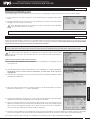
Thank you for your purchase of the Airtronics MT-S 2.4GHz FH4T radio control system. This User's Guide is intended to acquaint
you with the many unique features of your new radio control system.
The MT-S is designed for the user who wants more than an entry-level system, but doesn't need a top of the line system. The
MT-S falls perfectly between these two extremes, providing true Telemetry capability and Sanwa Synchronized Link (SSL)
support, with many additional programming features typically found only in higher end systems, all at a reasonable price that
makes the MT-S affordable for most users.
The MT-S has been designed for the utmost in comfort and precise control of all types of model cars and boats. We wish you
the best of success and fun with your new purchase! Please read this User's Guide carefully prior to use so that you may obtain
maximum success and enjoyment from the operation of your new radio control system.
IMPORTANT: Due to differences in the implementation of 2.4GHz technology among manufacturers, only Airtronics and
Sanwa branded FH3, and FH4T 2.4GHz surface receivers are compatible with your radio control system. Compatibility may
vary by region.
Full Telemetry support is available only when used with an Airtronics or Sanwa RX-461 or RX-462 FH4T Telemetry receiver, or when
the included RX-482 2.4GHz FH4T Super Response SSL receiver is used along with a Sanwa Super Vortex series ESC.
Sanwa Synchronized Link (SSL) support is available only when used with an Airtronics or Sanwa SSL receiver and a Sanwa
Super Vortex series ESC or other SSL accessory. Additional accessories are available through your local Airtronics or Sanwa retailer.
Not all features are supported by all receiver types. Some features are limited by receiver type.
INTRODUCTION
GENERAL
Airtronics shall not be liable for any damage resulting from the use of this product. As Airtronics has no control over the use,
setup, modification or misuse of this product, no liability shall be assumed nor accepted for any resulting damage or injury. By
the act of using this product, the user accepts all resulting liability. In No Case Shall Airtronics' liability exceed the original
cost of the purchased product.
LIABILITY STATEMENT
GENERAL
The packaging of your radio control system has been specially designed for the safe transportation and storage of the radio
control system's components. After unpacking your radio control system, do not discard the packaging materials.
Save the packaging materials for future use if you ever need to send your radio control system to us for service or to store
your radio control system if you don't plan on using it for an extended period of time.
PACKAGING
GENERAL
This is a high-output, full-range radio control system that should well exceed the range needed for any surface model. For safety,
the user should perform a range test at the area of operation to ensure that the radio control system has complete control of the
model at the farthest reaches of the operational area. We recommend that the user enlist the help of a fellow modeler to walk
the model to the farthest reaches of the track or other operational area, then test for proper operation.
In addition to the above, please observe the following and also make sure to read the various precautions on page 5.
• BecertaintoreadthisUser'sGuideinitsentirety.Think'SafetyFirst'foryourself,othersandyourequipment.Alwaysobserve
all the rules of the track or other operational area where you operate your radio control equipment.
• Ifatanytimeduringtheoperationofyourmodel,shouldyoufeelorobserveerraticoperationorabnormality,endyouroperation
as quickly and safely as possible. DO NOT operate your model again until you are certain the problem has been corrected.
• Yourmodelcancauseseriousdamageorinjury.Pleaseusecautionandcourtesyatalltimesduringuse.
• Donotexposetheradiocontrolsystemtowaterorexcessivemoisture.Ifusinginawetenvironment,waterproofthe
receiver by placing it in a water-tight radio box or wrapping it in a water-tight balloon.
• Ifyou have littletonoexperienceoperatingR/Cmodels, we recommend youseektheassistanceofanexperienced
modeler or your local hobby shop for guidance.
• TheLowVoltageAlertalarmwillsoundwhenthetransmitterbatteryvoltagedropstothedefaultthresholdof4.6volts.Ifthis
occurs, stop using the transmitter as soon as is safely possible, then replace or recharge the transmitter batteries.
The RX-482 2.4GHz FH4T Super Response SSL receiver included features an internal antenna. Do to the internal
antenna position, this receiver is not suitable for use in R/C boats. It should be used in R/C cars and trucks only.
This radio control system operates on the 2.4GHz frequency band. The 2.4GHz connection is determined by the
transmitter and receiver pair. Unlike ordinary crystal-based systems, your model can be used without frequency control.
SAFETY GENERAL
GENERAL

4
MT- S
2.4GHZ FH4T RADIO SYSTEM USER'S GUIDE
TR
Telemetry System with Sanwa Synchronized Link Support
For Service In North America:
Global Services/Airtronics
18480 Bandilier Circle
Fountain Valley, CA 92708
Telephone: (714) 963-0329
Fax: (714) 964-6236
Email: [email protected]
Sanwa Electronic Instrument CO., LTD.
1-2-50Yoshida-Honmachi
Higashiosaka, Osaka, 578-0982 Japan
Telephone: 81-729-62-1277
Fax: 81-729-64-2831
Email: [email protected]
Factory Service:
SERVICE AND SUPPORT
GENERAL
This product is warranted against manufacturer defects in materials and workmanship, at the original date of purchase. This
warranty does not cover components worn by use or damage caused by improper voltage, tampering, modification, misuse,
abuse, improper wiring, reverse polarity, moisture or using outside its intended scope of use.
Terms of this warranty can vary by region. Please read the warranty card included
with your radio control system for specific warranty information.
If you have any questions or concerns, we're here to help. If you encounter a problem with your radio control system, first check
the Troubleshooting Guide section on pages 65 and 66.
If you require further help that cannot be solved using the Troubleshooting Guide, or if you have technical questions, please
contact the Airtronics or Sanwa service center in your region.
For a complete list of distributors in your region, please visit www.sanwa-denshi.com/rc/distributors.html.
This equipment has been tested and found to comply with the limits for a Class B digital device, pursuant to Part 15 of the FCC
Rules. These limits are designed to provide reasonable protection against harmful interference in a residential installation.
This equipment generates, uses, and can radiate radio frequency energy and, if not installed and used in accordance with
the operating instructions, may cause harmful interference to radio communications. However, there is no guarantee that
interference will not occur in a particular installation.
If this equipment does cause harmful interference to radio or television reception, which can be determined by turning the
equipment OFF and ON, the user is encouraged to try to correct the interference by one or more of the following measures: (A)
Reorient or relocate the receiving antenna, (B) Increase the separation between the equipment and the receiver, (C) connect
the equipment into an outlet on a circuit different from that to which the receiver is connected and/or (D) consult the dealer or
an experienced technician for help.
This device complies with Part 15 of the FCC Rules. Operation is subject to the following two conditions:
(1) This device may not cause harmful interference, and...
(2) This device must accept any interference received, including interference that may cause undesired operation.
This device complies with Industry Canada's license-exempt RSSs, Operation is subject to the following two conditions:
(1) This device may not cause harmful interference, and...
(2) This device must accept any interference received, including interference that may cause undesired operation.
Le présent appareil est conforme aux CNR d’Industrie Canada applicables aux appareils radio exempts de licence. L’exploitation
est autorisée aux deux conditions suivantes:
(1) l’appareil ne doit pas produire de brouillage, et...
(2) l’utilisateur de l’appareil doit accepter tout brouillage radioélectrique subi, même si le brouillage est susceptible d’en
compromettre le fonctionnement.
Changes or modifications made to this equipment not expressly approved by Airtronics may void the FCC
authorization to operate this equipment.
RF Exposure Statement:
This transmitter has been tested and meets the FCC RF exposure guidelines when used with the Airtronics accessories supplied
or designated for this product, and provided at least 20cm separation between the antenna the user's body is maintained. Use
of other accessories may not ensure compliance with FCC RF exposure guidelines.
FCC COMPLIANCE STATEMENT GENERAL
Product features and specifications can vary by region. Not all products are legal for use in all regions.
Please note that products purchased outside of North America cannot be serviced under warranty by Global Services.
In some cases, we can make repairs for products purchased outside of North America, however, applicable repair costs
and shipping charges will be applicable. For warranty claims outside of North America, please contact the service center in
your region.

5
TR
MT- S
2.4GHZ FH4T RADIO SYSTEM USER'S GUIDE
Telemetry System with Sanwa Synchronized Link Support
• The2.4GHzfrequencybandmaybeusedbyotherdevices,orotherdevicesintheimmediateareamaycauseinterference
on the same frequency band. Always before use, conduct a bench test to ensure that the servos operate properly. Also,
conduct checks with the transmitter as distant as possible from your model.
• Theresponsespeedofthereceivercanbeaffectedifusedwheremultiple2.4GHztransmittersarebeingused,therefore,
carefully check the area before use. If response seems slow during use, stop your model immediately and discontinue use.
• Ifthe2.4GHzfrequencybandissaturated(toomanytransmittersturnedONatonce),asasafetyprecaution,thetransmitter
and receiver may not pair. This ensures that your radio control system does not get hit by interference. Once the frequencies
have been cleared, or the saturation level has dropped, your transmitter and receiver should pair without any problems.
• Topreventpossibledamagetoyourservosorarunawaymodel,turnthetransmitterONfirst,
then turn the receiver ON. After running your model, turn the receiver OFF first, then turn the
transmitter OFF.
• Beforeuse,double-checkthatthetransmitterandreceiverbatterieshavesufficient
power.
• Thetransmitterantennaismountedinternallyandislocatedintheleftfrontsideportionofthetransmitter,below
the carrying handle (see diagram on page 7). Do NOT cover this area in any way during use! Doing so can block
the RF signal, resulting in loss of control of your model.
• Duringuse,holdthetransmittersothatitsorientatedasclosetoverticalaspossibleatalltimes.ThisprovidesthebestRF
signal between the transmitter and the receiver. Try not to ever 'follow' your model with the transmitter,
as this can result in a weakened RF signal.
•Do not expose the transmitter or any other components to excessive heat,
moisture, fuel, exhaust residue, etc.
•Iftheoutercasebecomesdirty,itcanbecleanedwithasoftdrycloth.Iftheoutercasebecomes
soiled, it can be cleaned with a damp cloth and liquid detergent. Do not use any solvents to clean
the outer case. Solvents will damage the finish.
The RX-482 2.4GHz FH4T Super Response SSL receiver features an internal antenna. Do to the internal antenna position,
this receiver is not suitable for use in R/C boats. It should be used in R/C cars and trucks only. The MT-S radio system
can be used with R/C boats if you use a compatible receiver that features an external antenna, such as the RX-472 2.4GHz FH4T
Super Response SSL receiver.
• Althoughthereceptioncapabilityofthisreceiverisequaltoourotherreceiversthatfeatureanexternalantenna,because
the internal antenna is positioned lower in your model, the reception distance will be shorter in actual use.
• Forthebestreceptiondistancepossible,thetopofthereceiverMUSTbetowardthetopofyourmodelandthe receiver
should be mounted as high as possible in your model. The receiver can be mounted inside a receiver box, however, the
antenna position will be lower and the reception distance may be shorter.
•AnalogservosarenotcompatiblewithSHRorSSRChannelResponseModes.Ifusinganalogservos,youmustusetheNOR
Channel Response Mode. Analog servos can be damaged if you use them with SHR or SSR Channel Response Modes.
•AnybrandandtypeofdigitalservocanbeusedwiththeSHRChannelResponseMode,however,onlyAirtronicsorSanwa
Super Response SRG digital servos can be used with the SSR Channel Response Mode. If your ESC does not operate correctly
with the Throttle Channel Response Mode set to SHR or SSR, change the Throttle Channel Response Mode to NOR.
• The receiver is susceptible to vibration, shock and moisture. Take appropriate measures to protect against vibration and
moisture. It's okay to wrap the receiver in protective foam rubber if desired. Doing so will not affect the reception distance.
• There is a danger of runaway operation if connectors loosen during use. Make sure that all connectors are securely fitted.
• Withelectric-poweredmodels,besuretofitanybrushedmotorswithanoisesuppressioncapacitor.Withoutasuppression
capacitor, excessive electrical noise generation can cause runaway operation and result in damage to your model.
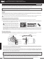
The RX-482 2.4GHz FH4T Super Response SSL receiver uses Airtronics 'Z' connectors, which are electronically compatible with
the servos of other radio control system manufacturers. The connectors are rugged, but should be handled with care.
When unplugging the servo connector, don't pull on the servo wire itself. This could result in damage to the servo wire
pins in the plastic plug. Always grasp the plastic connector itself.
- = Negative (Black)
+ = Positive (Red)
S = Signal (Blue)
If using another brand of servo, double-check the polarity
of the servo connector prior to plugging it into the receiver.
2.4GHZ FREQUENCY BAND PRECAUTIONS
GENERAL
GENERAL
TRANSMITTER PRECAUTIONS
GENERAL
GENERAL
RECEIVER PRECAUTIONS
GENERAL
SERVO CONNECTORS GENERAL
GENERAL

6
MT- S
2.4GHZ FH4T RADIO SYSTEM USER'S GUIDE
TR
Telemetry System with Sanwa Synchronized Link Support
• Normal, SHR and SSR Channel Response Modes
• DualThrottleMixingwithDigandBurnforRockCrawlers
• CODEAuxiliary
• StepAuxiliary
• PointAuxiliary
• AuxiliaryMixing
• ProgrammableFailSafe
• ReceiverBatteryVoltageFailSafe
• DigitalTrimsandServoSub-Trim
• ThrottleOffset
• AdjustableThrottleTriggerPosition
• AdjustableThrottleTriggerSpringTension
• AdjustableSteeringWheelTension
• ProgrammableSwitches
• VariableRateAdjustment
• ModelNaming
• ModelSelect
• ModelClear
• SelectableModulationType
• AdjustableLCDContrast
• AdjustableKeyVolumeandTone
• ProgrammableLowVoltageAlarm
• InactivityandOverVoltageAlarms
• DigitalBatteryVoltageMonitor
• SimplifiedProgrammingMenus
• SetupWizardwithEightCarTypes
• 20ModelMemory
• TelemetryLogging
• ServoReversing
• Steering,ThrottleandBrakeDualRate
• EndPointAdjustment
• AdjustableRateControl(ARC)Adjustment
• ServoSpeedAdjustment
• Anti-LockBraking
• Lap,IntervalandDownTimers
• Total,BestandIndividualLapDisplay
• FourWheelSteeringMixing
Transmitter:
• Model:MT-S(90478)
• OutputPower:60mW
• NominalInputVoltage:4.8vto7.4v
• OperatingVoltageRange:4.0vto9.6v
• DryWeight:12.9oz(366g)
• Frequency:2.4GHzFHSS
•ModulationType:FH3,FH4T(VariesbyRegion)
Receiver:
• Model:RX-482(92082)SuperResponseSSL
• NominalInputVoltage:3.7vto7.4v
• Weight:0.25oz (7.1g)
• Dimensions:0.71x0.96x1.06in(18.2x24.4x27.1mm)
• Frequency:2.4GHzFH3/FH4TSelectableViaTransmitter
• FailSafeSupport:Yes(AllChannels)
•BatteryVoltageFailSafeLimit:3.5to5.0v(FH3)/3.5to7.4v(FH4T)
• 4-Channel2.4GHzFH4TDigitalHigh-ResponseTelemetrySystemwithAdvancedProgramming
• BacklitLCDScreenAllowsYoutoEasilyViewProgrammingOptionsandTelemetryDatainAllTypesofConditions
• High-PowerFH4TTechnologyProvidestheBestReceptionandConnectivity,GivingRacersAddedAssurance
• 4-CellDryBatteryHolderforLighterWeight-AlsoAcceptsOptionalNiMHBatteriesor2SLiPoor2SLiFeBatteryPacks
•IncludesRX-4822.4GHzFH4TSuperResponseReceiverw/SanwaSynchronizedLinkSupport
SYSTEM FEATURES
GENERAL
SYSTEM SPECIFICATIONS GENERAL
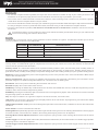
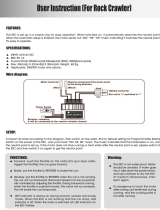
The following accessories are included with your MT-S. If an accessory is missing or if any parts appear damaged in any way,
please contact the Airtronics or Sanwa service center in your region. For more information, see the Service and Support section
on page 4. Contents may vary and are subject to change without notice.
• MT-S 2.4GHz FH4T Digital High-Response Transmitter
• RX-482(92082)SuperResponseSSLReceiver
WHAT'S INCLUDED GENERAL
• ReceiverOn/OffSwitch
• ReceiverDustBootCovers
ITEMS REQUIRED, BUT NOT INCLUDED GENERAL
Transmitter Batteries:
• Four'AA'AlkalineorNiMHcellsorone2SLiPoor2SLiFebatterypack.
Servos and ESCs:
• WerecommendusingdigitalservosandESCsthatsupportahighframeratewheneverpossible.Duetotheextremely
high frame rate of the MT-S transmitter and RX-482 Super Response SSL receiver, analog servos and many ESCs may
not be compatible when used with SHR or SSR Channel Response Modes. To prevent compatibility issues, use analog
servos only in the NOR Channel Response Mode. If your ESC does not work using the SHR Channel Response Mode, use
the NOR Channel Response Mode. Any brand and type of digital servo can be used with NOR or SHR Channel Response
Modes. Only Airtronics or Sanwa SRG series digital servos are compatible for use with the SSR Channel Response Mode.
Accessories:
• For a complete list of accessories, such as receivers, Telemetry sensors, ESCs, gyros and much more, please visit
www.airtronics.net (in North America only) or your local Airtronics or Sanwa authorized dealer. For a list of Sanwa distributors
in your region, visit www.sanwa-denshi.com/rc/distributors.html.

7
TR
MT- S
2.4GHZ FH4T RADIO SYSTEM USER'S GUIDE
Telemetry System with Sanwa Synchronized Link Support
Section Continued on Next Page
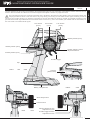
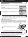
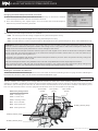
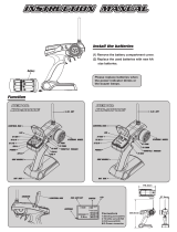
Use the diagrams in this section to familiarize yourself with the layout of your transmitter. Descriptions of these features can be
found in the Transmitter and Receiver Overview Diagram Descriptions section on pages 9 and 10.
The transmitter antenna is mounted internally and is located in the left front side portion of the transmitter, below the
carrying handle Do NOT cover this area in any way during use! Doing so can block the RF signal, resulting in loss of
control of your model. During use, hold the transmitter so that its orientated as close to vertical as possible at all times. This
provides the best RF signal between the transmitter and the receiver. Try not to ever 'follow' your model with the transmitter, as
this can result in a weakened RF signal.
TRANSMITTER OVERVIEW DIAGRAMS
GENERAL
Antenna
(Inside Case)
Trim Switch
(Trm1)
Battery Compartment
Auxiliary Switch (Sw2)
Throttle Trigger
Grip
Auxiliary Switch (Sw3)
Trim Switch
(Trm3)
Trim Switch
(Trm2)
Throttle Trigger Tension
Adjustment Screw
RIGHT SIDE VIEW
Throttle Trigger Position
Adjustment Screw
Steering Wheel Tension
Adjustment Screw
FRONT VIEW
Wrist Strap Anchor
Power Switch
BACK VIEW
Auxiliary Switch (Sw1)
GENERAL

8
MT- S
2.4GHZ FH4T RADIO SYSTEM USER'S GUIDE
TR
Telemetry System with Sanwa Synchronized Link Support
Section Continued on Next Page
LCD Screen
ENTER Key
BACK Key
Auxiliary Switch (Sw2)
Trim Switch (Trm1)
Trim Switch (Trm3)
Trim Switch (Trm2)
TOP VIEW
TRANSMITTER OVERVIEW DIAGRAMS
GENERAL
UP Key
DOWN Key
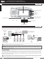
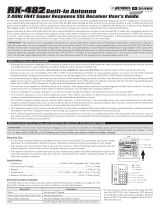
RECEIVER OVERVIEW DIAGRAM, CONNECTIONS AND MOUNTING
GENERAL
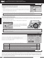
Use the diagrams in this section to make receiver connections and to familiarize yourself with the RX-482 2.4GHz FH4T Super
Response SSL receiver included with your MT-S radio control system. Descriptions of the features can be found in the Transmitter
and Receiver Features Descriptions on the next two pages.
Steering
Channel 1
Throttle
Channel 2
Auxiliary 1
Channel 3
Auxiliary 2
Channel 4
On/Off Switch
'AA' Dry Cell Battery Holder
3.7v to 7.4v NiMH Battery Pack
2S LiPo or LiFe Battery Pack
On/Off Switch
To Battery
Throttle
Channel 2
Glow/Gas
Setup
ESC
Setup
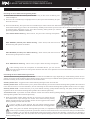
If using a Sanwa Super Vortex series ESC, plug the ESC into the SSL slot, otherwise SSL features and Telemetry Data will
not be available. All other ESC's should be plugged into CH 2.
BATT
SSL
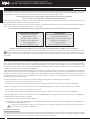
IMPORTANT: The RX-482 2.4GHz FH4T Super Response SSL receiver does not feature full Telemetry support (e.g.,
Temperature data and RPM data). Full Telemetry capability is supported only when used with a Sanwa Super Vortex series
ESC plugged into the BATT/SSL port.
= Signal
= Positive
= Negative
TOP
Bind Button
Bind LED
TOP
Antenna
TOP
Powering the Receiver:
The receiver's Nominal Input Voltage range is 3.7 to 7.4 volts. If you're using the receiver in a glow- or gas-powered model,
you can use up to a 2S 7.4V LiPo battery pack to power the receiver and your servos. If you're using the receiver in an electric
model, you can adjust your ESC's BEC power output to 7.4 volts (if applicable - refer to your ESC User's Guide for information)
to power the receiver and your servos. This allows you to take advantage of the higher torque and speed provided by 7.4 volt
digital servos commonly used today.
Most "standard voltage" servos are designed to be used with a nominal input voltage of 4.8 to 6.0 volts. High voltage
servos are designed for use with a nominal input voltage of 6.6 to 7.4 volts. Do NOT use "standard voltage" servos with a
nominal input voltage higher than 6.0 volts or your servos can be damaged!
Steering Wheel
LED Condition Indicator

9
TR
MT- S
2.4GHZ FH4T RADIO SYSTEM USER'S GUIDE
Telemetry System with Sanwa Synchronized Link Support
Section Continued on Next Page
Antenna: Transmits the signal from the transmitter to the receiver in the model. Never touch the Antenna during use. Doing
so may result in a weakened RF signal or complete loss of control of your model. The receiver also features an antenna that
receives the RF signal from the transmitter.
Auxiliary Switch: The transmitter features three separate Auxiliary Switches (Sw1, Sw2 and Sw3). Each Auxiliary Switch is
programmable and will perform a different function depending on what function is assigned to it. Auxiliary Switch (Sw1) is a
push-button switch, Auxiliary Switch (Sw2) is a 2-position sliding switch and Auxiliary Switch (Sw3) is a 3-position sliding switch.
BACK Key: Pressing the BACK Key returns the Programming Cursor to the previous menu. Press and HOLD the BACK Key to
return to the STATUS screen.
Battery Compartment: Houses the four 'AA' Alkaline cells that power the transmitter. Alternatively, the transmitter can be
powered using four 'AA' NiMH rechargeable batteries or a 2S LiPo or 2S LiFe battery pack.
Bind Button: Used in the process of binding the transmitter and receiver.
Bind LED: Displays the current status of the receiver.
DOWN Key: Pressing the DOWN Key scrollsbetweentheSTATUSandTELEMETRYscreens,scrollstheProgrammingCursor
DOWN or LEFT and Decreases Programming Values.
ENTER Key: Pressing the ENTER Key opens the selected menu or Programming Option. Press and HOLD to reset the selected
Programming Option to its default value.
Grip: The Grip is molded in an ergonomic shape for Increased comfort, control and feel.
LCD Screen: The heart of the programming and display features of the transmitter. All programming and transmitter display
functions are shown on the LCD screen.
LED Condition Indicator: Displays the current RF signal output status of the transmitter, in addition to various other transmitter
conditions.
Power Switch: Turns the transmitter ON and OFF.
Steering Wheel: Proportionally operates the model's right and left steering control. The Steering Wheel features a foam grip for
Increased comfort, control and feel. In addition, the Steering Wheel spring tension can be adjusted.
Steering Wheel Tension Adjustment Screw: Used to adjust the spring tension of the Steering Wheel to best suit the feel of
the user.
Throttle Trigger: Controls the speed of the model, both forward and backward, or the model's brake. The Throttle Trigger position
and spring tension can both be adjusted.
Throttle Trigger Tension Adjustment Screw: Used to adjust the spring tension of the Throttle Trigger to best suit the feel of
the user.
RECEIVER OVERVIEW DIAGRAM, CONNECTIONS AND MOUNTING
GENERAL
Mounting Tips:
• Forthebestreceptiondistancepossible,thetopofthereceiverMUSTbetowardthetopofyourmodel(asshowninthe
illustration on the previous page) and the receiver should be mounted as high as possible in your model.
• The receiver can be mounted inside a receiver box, however, when mounting inside a receiver box, the antenna position
will be lower and the reception distance may be shorter.
• The receiver should be mounted securely to your model using a piece of double-sided foam tape to help minimize vibration.
It's okay to wrap the receiver in protective foam rubber, if desired. Doing so will not affect the reception distance.
• Dototheinternalantennaposition,this receiver is not suitable for use in an R/C boat. It should be used in R/C cars and
trucks only.
As a safety precaution, set your model on a stand so the wheels are off the ground before turning on your radio control
system or connecting your motor for the first time.
Bind LED:
The Bind LED on the receiver can be used to determine receiver condition at a glance. The Bind LED will alert you to various
receiver conditions, as shown in the table below.
Blue
Blue
Red & Blue
Red
Receiving RF Signal
Binding Operation
Receiver Battery Fail Safe Activates
No RF Signal After Receiver Battery Fail Safe Activates
LED COLOR
RECEIVER STATUS
LED CONDITION
ON
Slow Flash/Fast Flash
Flash
ON
TRANSMITTER AND RECEIVER OVERVIEW DIAGRAM DESCRIPTIONS
GENERAL
GENERAL

10
MT- S
2.4GHZ FH4T RADIO SYSTEM USER'S GUIDE
TR
Telemetry System with Sanwa Synchronized Link Support
TRANSMITTER AND RECEIVER OVERVIEW DIAGRAM DESCRIPTIONS
GENERAL
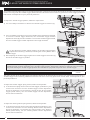
Throttle Trigger Position Adjustment Screw: Used to adjust the position of the Throttle Trigger either forward or backward.
Trim Switch: The transmitter features three separate Trim Switches positioned around the Steering Wheel (Trm1, Trm2 and
Trm3). Each Trim Switch is programmable and will perform a different function depending on what function is assigned to it.
For example, Trm1 and Trm2 can be used to adjust steering and throttle Trim and Trm3 can be used to adjust steering Dual Rate.
UP Key: Pressing the UP Key scrollsbetweentheSTATUSandTELEMETRYscreens,scrollstheProgrammingCursorRIGHTor
UP and Increases Programming Values.
Wrist Strap Anchor: Used to attach the wrist strap anchor to the transmitter.
TRANSMITTER LED CONDITION INDICATOR AND WARNING ALARMS
GENERAL
The MT-S is equipped with several different Audible Warning Alarms to warn you of an abnormal transmitter condition. In
addition, the LED Condition Indicator is used to indicate various conditions at a glance.
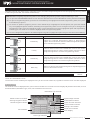
LED Condition Indicator
The LED Condition Indicator is used to indicate various transmitter conditions at a glance. Some of the conditions indicated by
the LED may also be accompanied by an audible alarm and/or and on-screen warning.
ON
Flash Rapidly
Flash Rapidly, Then Pause
Flash Slowly
Flash Rapidly, Then Pause
Flash Rapidly, Then Pause
Flash Rapidly
Flash Rapidly
Flash Slowly
Flash Slowly
TRANSMITTER STATUS LED
RF Output Signal
Anti-Lock Braking Function Active
Throttle Offset Function Active
Low Voltage Alert Alarm Active
Telemetry Alarm Active
Inactivity Alarm Active
Low Voltage Limit Alarm Active
Over Voltage Alarm Active
RF Binding - Sending Bind Code
Telemetry Logger Function Active
REMARK
Normal Operation
Press ENTER or BACK Key to Cancel
Press ENTER or BACK Key to Cancel
Replace Batteries
Battery Voltage Too High
Audible Warning Alarms
The audible alarms listed below and on the next page may also be accompanied by an on-screen warning.
Inactivity (Power ON) Alarm:
The Inactivity Alarm will sound if the transmitter is left on for a period of 10 minutes without any control input from the user. This
alarm alerts you to prevent unwanted draining of the transmitter battery.
To clear this alarm, either turn the transmitter OFF or press the ENTER or BACK key.
Over Voltage Alarm:
The Over Voltage Alarm will sound if the transmitter battery voltage is greater than 9.6 volts.
To clear this alarm, turn the transmitter OFF and replace the transmitter battery with one that when fully charged does not
exceed 9.6 volts.
Low Voltage Alert Alarm:
The Low Voltage Alert alarm will sound when the transmitter batteries reach the Low Voltage Alert alarm voltage value
programmedintheSYSTEM>ALARMmenu.ThealarmwillsoundeachtimethetransmitterbatteryvoltageDecreasesby0.1volt.
To clear this alarm, press the ENTER or BACK key.
Low Voltage Limit Alarm:
The Low Voltage Limit alarm will sound when the transmitter batteries reach the Low Voltage Limit alarm voltage value
programmedintheSYSTEM>ALARMmenu.
This alarm can only be cleared by turning the transmitter OFF and replacing or recharging the transmitter batteries.
Telemetry Alarm:
The Telemetry alarm will sound when the Temperature 1 Alert alarm, Temperature 2 Alert alarm and/or the Voltage Alert
alarmreachtheAlertvalueprogrammedintheSYSTEM>TELEMETRYmenu.
To clear this alarm, press the ENTER or BACK key.

11
TR
MT- S
2.4GHZ FH4T RADIO SYSTEM USER'S GUIDE
Telemetry System with Sanwa Synchronized Link Support
The MT-S transmitter has a Nominal Input Voltage range of 4.8 to 7.4 volts and an Operating Voltage Range of 4.0 to 9.6 volts.
This allows you to use several different battery types, depending on your preference. Use the information below to determine
what type of battery to use.
Alkaline - In the default configuration, the transmitter is designed to be powered using four 'AA' Alkaline batteries. This results
in a transmitter that is lightweight and well-balanced for unmatched comfort. Install the four 'AA' Alkaline batteries into the
battery holder included.
NiMH - Rechargeable NiMH batteries of desired capacity can be used in place of the Alkaline batteries. Using rechargeable
NiMH batteries is more convenient and cheaper in the long run. The higher capacity batteries will also provide longer usage
time than most Alkaline batteries. Install the four NiMH batteries into the battery holder included.
LiPo or LiFe - A 2-cell LiPo or LiFe battery pack can be used to power the transmitter. These battery packs are popular due
to their light weight and high capacity for long usage time between charges. Remove the battery holder first, then install the
LiPo or LiFe battery pack.
Transmitter power output, range and speed are the same, regardless of the battery type used. If using a LiPo or LiFe
battery pack, please read the Warnings if Using a LiPo or LiFe Battery Pack section below.
2) Install four fresh 'AA' Alkaline batteries into the battery holder, making sure that the polarity is correct. The direction that each
battery should be installed is molded into the bottom of the battery holder (+ Positive and - Negative).
3) Reinstall the battery holder into the transmitter, making sure that the batteries toward bottom of the transmitter (so the
smooth bottom of the battery holder will be toward the battery cover). This will prevent the battery cover from hitting or
catching on the batteries when you reinstall it.
4) Slide the battery cover back onto the transmitter and push it firmly until it 'clicks' closed.
TRANSMITTER BATTERY OPTIONS
GENERAL
ALKALINE BATTERY INSTALLATION
GENERAL
1) Remove the battery cover from the bottom of the transmitter by pushing firmly on the battery cover in the direction of the arrow
and sliding it off.
Remove the battery holder and double-check that the battery holder is plugged in. If it isn't, plug the connector on the
battery holder into the matching connector in the transmitter.
• UseONLYa2-CellLiPoorLiFebatterypackofdesiredcapacity.
• TheMT-Stransmitterdoesnotfeatureachargejack.Forthesafetyofboththebatterypackandthetransmitteritself,the
battery pack must be removed from the transmitter during the charging process.
• UseabalancechargerspecificallydesignedtochargeLiPoorLiFebatterypacks.Chargethebattery pack inanopen
area free of any obstructions.
• Whenchangingtheconnectoronyourbatterypacktomatchthebatteryconnectorinthetransmitter,
please observe correct polarity. Connecting with reverse polarity will damage the transmitter.
• ObserveallsafetyprecautionsprovidedwithyourLiPoorLiFebatterypack.
•Donotleavethebatterypackunattendedduringthechargingprocess.
• Ifthebatterypackappearsswollenorotherwisedamaged,donotuseitorchargeit.Itshouldbediscardedandreplaced.
• Damageto thetransmittercausedby improperuse,wrong batterytype,incorrectvoltage orreversepolarity will notbe
covered under warranty!
The transmitter has a Nominal Input Voltage range of 4.8 to 7.4 volts. DO NOT USE A 3-CELL LiPo or LiFe battery pack
or the transmitter will be damaged! Use a 2-Cell LiPo or LiFe battery pack only!
- = Negative (Black)
+
= Positive (Red)
WARNINGS IF USING A LIPO OR LIFE BATTERY PACK
GENERAL
IMPORTANT:You must change the transmitter battery Low Voltage Alert and Low Voltage Limit alarms to match the
battery type you're using or else you may receive erroneous low voltage alarms during use, or worse run your battery
downsolowastodamageit.Formoreinformation,seetheBATTERYMenusectiononpages60through62.
Yourbatterypackmustnotexceed9.6voltswhenfullychargedorthetransmitterOverVoltagealarmwillsoundwhen
the transmitter is turned ON.
GENERAL

12
MT- S
2.4GHZ FH4T RADIO SYSTEM USER'S GUIDE
TR
Telemetry System with Sanwa Synchronized Link Support
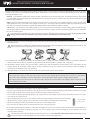
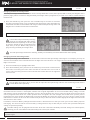
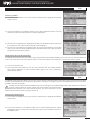
The position of the Throttle Trigger can be adjusted forward or backward to change the feel of the Throttle Trigger during use.
Some users may prefer the Throttle Trigger positioned farther forward and some users my prefer the Throttle Trigger positioned
farther back. It all depends on your personal preference.
THROTTLE TRIGGER POSITION ADJUSTMENT
GENERAL
B
A
C
IMPORTANT: The Throttle Trigger adjustment range is approximately 7mm. Do not attempt to adjust the Throttle Trigger
position beyond the limits indicated by the Throttle Trigger Position Adjustment Indicator or damage to the transmitter
may result. Moving the Throttle Trigger position does not affect the physical end points of the Throttle Trigger.
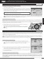
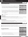
To adjust the Steering Wheel spring tension, follow the step below:
1) To Increase the spring tension of the Steering Wheel (make firmer), use
a 1.5mm hex wrench to turn the Steering Wheel Tension Adjustment
Screw (A) clockwise. To Decrease the spring tension of the Steering
Wheel (make looser), turn the Steering Wheel Tension Adjustment
Screw counter-clockwise.
A
The spring tension of the Throttle Trigger and Steering Wheel can be adjusted to best suit the user. Some users may prefer the
Throttle Trigger and/or Steering Wheel to feel firmer and some users may prefer them to feel softer. It all depends on your
personal preference.
A
To adjust the Throttle Trigger spring tension, follow the step below:
1) To Increase the spring tension of the Throttle Trigger (make firmer), use
a 1.5mm hex wrench to turn the Throttle Trigger Tension Adjustment
Screw (A) clockwise. To Decrease the spring tension of the Throttle
Trigger (make looser), turn the Throttle Trigger Tension Adjustment
Screw counter-clockwise.
THROTTLE TRIGGER AND STEERING WHEEL SPRING TENSION ADJUSTMENT
GENERAL
To adjust the Throttle Trigger position, follow the steps below:
1) Use a # 1 Philips screwdriver to loosen the Throttle Trigger Lock Screw (A).
2) Use a # 1 Philips screwdriver to move the Throttle Trigger forward or backward.
To move the Throttle Trigger backward, turn the Throttle Trigger Position
Adjustment Screw (B) counter-clockwise. To move the Throttle Trigger forward,
turn the Throttle Trigger Position Adjustment Screw (B) clockwise.
As you adjust the Throttle Trigger position, the Throttle Trigger Position
Adjustment Indicator (C) will move, indicating the current position of the
Throttle Trigger.
3) After adjusting the Throttle Trigger, tighten the Throttle Trigger Lock Screw (A)
to lock the Throttle Trigger in position.

13
TR
MT- S
2.4GHZ FH4T RADIO SYSTEM USER'S GUIDE
Telemetry System with Sanwa Synchronized Link Support
Section Continued on Next Page
Used to select STATUS and TELEMETRY screens and various
Programming Menus. Used to select specific channels in some
Programming Menus. Decreases Programming Values.
PROGRAMMING KEY NAME FUNCTION
ENTER Key
Opens the selected Programming Menu or Programming
Option. Press and HOLD to reset the selected Programming Option
to its default Programming Value.
BACK Key
Returns to the previous Programming Menu. Repeatedly press to
return to the STATUS screen.
Navigating through the Status screen, Telemetry screen, the various Programming Menus and changing Programming Values
is done using the ENTER, UP, DOWN and BACK keys.
PRO TIP: While navigating Programming Menus and changing Programming Values, keep the following in mind:
(A) ToopenthePROGRAMMINGMENUscreenfromtheSTATUSscreenortheTELEMETRYscreen,presstheENTERkey.
(B) To open a Programming Menu, press the UP or DOWN keys to highlight the desired Programming Menu, then press
the ENTER key to open it.
(C) To choose an option to program, press the UP or DOWN keys to highlight the desired option, then press the ENTER
key. The highlighted option will flash, indicating the Programming Value can be changed. Once you've changed the
Programming Value, press the ENTER key again or press the BACK key and the highlighted option will stop flashing,
indicating you can scroll UP or DOWN to highlight another Programming Option.
(D) To reset a Programming Option to its default Programming Value, highlight the option and press the HOLD the ENTER key.
Used to select STATUS and TELEMETRY screens and various
Programming Menus. Used to select specific channels in some
Programming Menus. Increases Programming Values.
UP Key
PROGRAMMING KEYS OVERVIEW AND FUNCTIONS GENERAL
DOWN Key
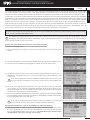
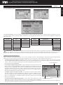
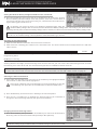
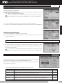
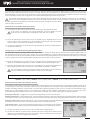
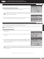
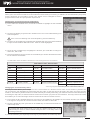
STATUS Screen:
The STATUS screen is displayed when you turn the transmitter ON. The STATUS screen displays all pertinent information, such as
the Model Name, Modulation Type, Timer, Servo Monitor and much more.
STATUS SCREEN AND TELEMETRY SCREEN OVERVIEW
GENERAL
Use the information in this section to familiarize yourself with the layout and different indicators that comprise the STATUS
screenandTELEMETRYscreen.
The STATUS screen will always be displayed when you turn the transmitter ON, regardless of which screen was last displayed.
Model Number and Name
Timer Display
Digital Voltage Indicator
Steering Trim Indicator
Throttle Trim Indicator
Servo Monitor
Throttle Mode Indicator
System Function Indicator
Screen Position Indicator
Timer Type Indicator
Steering Program Indicator
Throttle Program Indicator
Modulation Type Indicator
GENERAL

14
MT- S
2.4GHZ FH4T RADIO SYSTEM USER'S GUIDE
TR
Telemetry System with Sanwa Synchronized Link Support
TELEMETRY Screen:
TheTELEMETRYscreendisplaysTelemetryData,suchasRPMorSpeed,TemperatureandReceiverVoltage.
STATUS SCREEN AND TELEMETRY SCREEN OVERVIEW
GENERAL
Screen Position Indicator
Receiver Voltage Indicator
Temperature 1 Indicator
Telemetry Signal Indicator
UP/DOWN
Temperature 2 Indicator
RPM Indicator
PresstheDOWNandUPkeystoswitchbetweentheSTATUSandTELEMETRYScreens.
STATUS Screen and TELEMETRY Screen Overview Diagram Descriptions:
Digital Voltage Indicator: Indicates the current Voltage of the transmitter batteries.
Modulation Type Indicator: Indicates the current Modulation Type that the transmitter is set to.
Model Number and Name: Displays the Model Number and Model Name of the currently selected model.
Receiver Voltage Indicator: Indicates the current Voltage of the receiver battery.
RPM Indicator: Indicates the current RPM from the RPM Telemetry sensor (available separately).
Screen Position Indicator:IndicatesthecurrentActivescreen,eithertheSTATUSscreenortheTELEMETRYscreen.
Servo Monitor: Displays the output levels of the four different channels in bar graph form, allowing you to monitor servo operation
in a virtual manner.
Steering Program Indicator: Indicates up to four different programming options that are currently programmed to the Steering
channel. The Steering Program Indicator will only be displayed if a Steering channel Programming Value is programmed. For
example, Steering Dual Rate.
Steering Trim Indicator: Indicates the current position of the Steering Trim Switch.
System Function Indicator: Indicates current System Functions, such as TELE (Telemetry) or LOG (Logger) that are turned ON.
Telemetry Signal Indicator: Indicates the current signal strength of the Telemetry connection between the transmitter and
receiver. The Telemetry Signal Indicator will only be displayed when the receiver is turned ON and there is a Telemetry
connection Active.
Temperature 1 Indicator: Indicates the current Temperature from the Temperature 1 Telemetry Sensor (available separately).
Temperature 2 Indicator: Indicates the current Temperature from the Temperature 2 Telemetry Sensor (available separately).
Throttle Mode Indicator: Indicates the current Throttle Mode type, either 7:3 or 5:5.
Throttle Program Indicator: Indicates up to four different programming options that are currently programmed to the Throttle
channel. The Throttle Program Indicator will only be displayed if a Throttle channel Programming Value is programmed, for
example, Throttle Dual Rate).
Throttle Trim Indicator: Indicates the current position of the Throttle Trim Switch.
Timer Display: Displays the time of the currently selected Timer.
Timer Type Indicator: Indicates the current Timer Type selected, either LAP, INT (Interval) or DWN (Down).
Full Telemetry support is available only when used with an Airtronics or Sanwa RX-461 or RX-462 FH4T Telemetry receiver,
or when the included RX-482 2.4GHz FH4T Super Response SSL receiver is used along with a Sanwa Super Vortex
series ESC.

15
TR
MT- S
2.4GHZ FH4T RADIO SYSTEM USER'S GUIDE
Telemetry System with Sanwa Synchronized Link Support
Section Continued on Next Page
SETUP WIZARD
CAR TYPE TEMPLATES
GENERAL
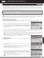
The Setup Wizard allows you to quickly and easily program the transmitter based on the type of model you're driving. Eight
Car Type Templates are provided. When a Car Type Template is selected, functions are automatically Assigned to the correct
channel and to the Auxiliary Switches and Trim Switches. This takes the guess-work out of setting up more complex models.
For example, if your Rock Crawler features Front and Rear Steering servos and Front and Rear Motors, choosing the CRAWLER
4WS/MOA Car Type Template will automatically program the transmitter for Four Wheel Steering Mixing and Motor on Axle
Mixing. In addition, various functions will be Assigned to the Auxiliary Switches and Trim Switches. The Setup Wizard will also
display what receiver channel ports to plug the servos into since this will vary depending on the Car Type Template chosen.
After choosing the desired Car Type Template, you can then choose the desired Modulation Type of your receiver, choose the
desired Channel Response Mode for each of the four channels, then Bind the transmitter and receiver. After Binding, you can
then change Servo Reversing, Sub-Trim and EPA programming values to finish the Setup Wizard.
WARNING: the Setup Wizard is designed to be used when setting up a new model and should be done prior to making any
programming changes to your model. When you run the Setup Wizard, all Programming Data (including custom Programming
Data) for the selected model will be LOST!
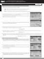
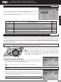
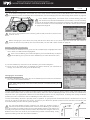
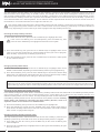
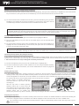
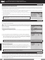
Starting the Setup Wizard and Choosing a Car Type Template:
1) Turn the transmitter OFF.
2) Press and HOLD the ENTER key, then turn the transmitter ON to open the Setup
Wizard.
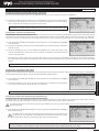
6) Press the UP or DOWN keys to select the Car Type that matches the type of model
you're setting up, for example, CRAWLER 4WS/MOA. What channel ports to plug
the servos into your receiver and what functions will be controlled by what Auxiliary
Switches and Trim Switches will be displayed.
7) PresstheENTERkey.INITIALIZE?NO/YESwillbedisplayed.PresstheUPorDOWN
keystohighlightYES,thenpresstheENTERkey.INITIALIZINGwillflashmomentarily,
then the RF MODE SET menu will open.
If you want to go back and select a different Car Type Template or you don't want to create the new Car Type Template
for any reason, choose NO or press the BACK key before Initializing.
3) Press the ENTER key to start the Setup Wizard and open the SELECT MODEL menu.
4) Press the UP or DOWN keys to highlight the model you would like to set up.
5) PresstheENTERkey.Selectthismodel?NO/YESwillbedisplayed.PresstheUPor
DOWNkeystohighlightYES,thenpresstheENTERkeytoopentheSELECTCAR
TYPEmenu.
If you want to go back and select a different model or you don't want to create
the new Car Type Template for any reason, choose NO or press the BACK key.
For detailed information about specific programming options that can be changed through the Setup Wizard, such as
Binding the transmitter and receiver, Modulation Type, Channel Response Mode, Servo Reversing, etc., please refer to
those specific sections in this User's Guide.
Changing the Modulation Type, Channel Response Mode and Binding:
1) After selecting the Car Type Template, the RF MODE SET menu will be open. Press
the UP or DOWN keys to select the desired Modulation Type, then press the ENTER
key. The RESPONSE MODE menu will open. The Modulation Type should match
the Modulation Type of the receiver you're using!
GENERAL

16
MT- S
2.4GHZ FH4T RADIO SYSTEM USER'S GUIDE
TR
Telemetry System with Sanwa Synchronized Link Support
SETUP WIZARD
CAR TYPE TEMPLATES
GENERAL
Changing the Modulation Type, Channel Response Mode and Binding, Continued:
2) Press the UP or DOWN keys to highlight the desired channel you would like to change the Channel Response Mode for.
3) Press the ENTER key, then press the UP or DOWN keys to choose the desired
Channel Response Mode value for the selected channel.
4) Press the ENTER key, then repeat steps 1 and 2 to choose the Channel Response
Mode for any desired remaining channels.
The following Channel Response Modes are available:
NOR - Use with any brand of Analog or Digital servos (Slowest Response Time).
SHR - Use with any brand of Digital servos only (Faster Response Time).
SSR - Use with Airtronics or Sanwa Super Response SRG Digital servos only (Fastest Response Time) - FH4T Only.
5) Press the UP or DOWN keys to highlight NEXT, then press the ENTER key to open the
BIND to RX menu. NEXT will be highlighted.
6) Hold the Bind button down on the receiver, then turn the receiver ON. The Bind LED on the receiver will flash slowly. Release
the Bind Button. The Bind LED will continue to flash slowly.
7) Press the ENTER key. The NEXT command and the LED on the transmitter will begin to flash and the Bind LED on the
receiver will flash rapidly, then go out.
8) After the Bind LED on the receiver goes out, press the ENTER key a second time. Both the Bind LED on the receiver and the
LED on transmitter will illuminate solid, indicating that the Binding procedure is complete and the BASE SETTING menu
will open.
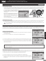
Changing the Base Setting Programming Values:
1) After completing the Binding process, the BASE SETTING menu will be open. Press
the UP or DOWN keys to highlight the desired Programming Option you want to
change for the ST (Steering), TH (Throttle), A1 (Auxiliary 1) or A2 (Auxiliary 2) channels.
2) Press the ENTER key, then press the UP or DOWN keys to choose the desired value
for the selected Programming Option.
3) Press the ENTER key, then repeat steps 1 and 2 to change the values for any remaining
Programming Options.
4) After making all your desired programming changes, press the UP or DOWN keys
to highlight FINISH, then press the ENTER key twice to finish the Setup Wizard. The
Setup Wizard will close and the STATUS screen will be displayed.

17
TR
MT- S
2.4GHZ FH4T RADIO SYSTEM USER'S GUIDE
Telemetry System with Sanwa Synchronized Link Support
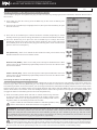
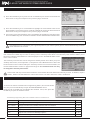
PROGRAMMING MENU STRUCTURE OVERVIEW
GENERAL
The MT-S features a PROGRAMMING screen that is accessed by pressing the ENTER key from either the STATUS screen or
theTELEMETRYscreen.
SETTING
D/R
SPEED
CURVE
F/S
BASE
FUNC
AUX
STEP
POINT
4WS
MOA
AUX MIX
CODE
MODEL
MODEL SELECT
MODEL NAME
MODELCOPY
MODEL CLEAR
TIMER
LAP
INT
DOWN
SYSTEM
BIND
KEYASSIGN
BUZZER
BATTERY
LCD
VR ADJUST
TELEMETRY
LOGGER
ALERT SETTING
TELEMETRYSETTING
Press ENTER Key
OR
The PROGRAMMING screen contains all of the MT-S's various Programming Menus, categorized into six different menus.
To access these menus, press the UP or DOWN keys to highlight the desired menu, then press ENTER key to open the
selected menu.
Some Programming Menus contain more sub-menus than those shown, and those sub-menus will vary depending
onthechannelselected.Forexample,TheFUNC>STmenucontainstheTRIMmenu,however,theFUNC>THmenu
containstheTRIMmenu,inadditiontoThrottle-specificprogramming,suchastheALB,OFFSETandTHTYPEmenus.
Navigating Programming Menus:
When you open a Programming Menu, the cursor will flash over the Channel/Options along the top of the Programming
Menu screen, which consists of either four channels (ST, TH, A1 and A2) or other options (CH, SET, etc.).
To Select the Desired Channel or Option - When the cursor is flashing over a channel or option, press the UP or DOWN
keys to highlight the desired channel or option you want to make programming changes to, then press the ENTER key to
select it. The cursor will stop flashing and the first Programming Value that can
be changed will be highlighted.
To Change Programming Values - After selecting the desired channel or
option, the cursor will stop flashing and the first Programming Value that can be
changed will be highlighted. Press the UP or DOWN keys to select the desired
Programming Value you want to change, then press the ENTER key. The cursor
will flash over the selected Programming Value. Press the UP or DOWN keys to
change the highlighted Programming Value.
To Select Another Channel or Option - At any time you want to select another
channel or option to make programming changes to, press the BACK key until
thecursorisflashingoveroneofthefourchannelsoroptions.Youcanthenpress
the UP or DOWN keys to highlight another channel or option, then press the
ENTER key to select it.
To Select Another Programming Menu - Press either the ENTER key or the
BACK key so that no cursor is flashing. Press the UP or DOWN keys to highlight
thedesiredProgrammingMenu,thenpresstheENTERkeytoopenit.Youcanthenselectthedesiredchanneloroptionand
change the desired Programming Value as described above.
GENERAL
Channel/Options
Programming Menus
Programming Values

18
MT- S
2.4GHZ FH4T RADIO SYSTEM USER'S GUIDE
TR
Telemetry System with Sanwa Synchronized Link Support
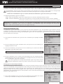
4) Press the UP or DOWN keys to highlight the ENTER command. Do not press the
ENTER key yet.
Verify that the Modulation Type is set to RF MODE : FH4T and that the Channel
Response Mode for each channel is set to NOR. If you need to change any of
these settings, see the BIND Menu section on pages 55 and 56.
3) Press theENTERkeytoopentheSYSTEMmenu,thenpresstheENTERkeytoopen
the BIND menu.
5) While holding down the Bind Button on the receiver, turn the receiver ON. The
Bind LED on the receiver will flash slowly. Release the Bind Button. The Bind
LED will continue to flash slowly.
Youmustcompletestep5belowwithin10secondsortheBindLEDwill
go out, indicating the receiver has timed out. If this occurs, turn the
receiver OFF, then repeat step 4.
8) Move the Steering Wheel and Throttle Trigger to verify that the servos are operating normally, then repeatedly press and
HOLD the BACK key to return to the STATUS screen.
Under some circumstances, the receiver may not operate after turning the transmitter and receiver ON. If this occurs,
perform the Binding procedure again.
6) With ENTER highlighted, press the ENTER key. The ENTER command and the LED
on the transmitter will begin to flash and the Bind LED on the receiver will flash
rapidly, then go out.
7) After the Bind LED on the receiver goes out, press the ENTER key a second time. Both the Bind LED on the receiver and the
LED on transmitter will illuminate solid, indicating that the Binding procedure is complete.
The Binding function allows you to Bind the transmitter and receiver pair. When new, it is necessary to pair the transmitter and
receiver to prevent interference from transmitters operated by other users. This operation is referred to as 'Binding'. Once the
Binding procedure is complete, the setting is remembered even when the transmitter and receiver are turned OFF, therefore,
this procedure usually only needs to be done once.
Before beginning the Binding procedure, connect the switch harness, servos and the receiver battery to your receiver,
using the diagram in the Receiver Overview Diagram, Connections and Mounting section on pages 8 and 9. Make sure
that both the transmitter and the receiver are turned OFF.
IMPORTANT: This section details Binding the RX-482 2.4GHz FH4T Super Response SSL receiver with the Channel Response
Mode set to SHR. If you are Binding an FH3 receiver, or if you prefer to change the Channel Response Mode, see the BIND
Menu section on pages 55 and 56.
TRANSMITTER AND RECEIVER BINDING
GENERAL
1) Turn the transmitter ON. The STATUS screen should be displayed.
2) Press the ENTER key to open the PROGRAMMING screen, then press the UP or
DOWNkeystohighlighttheSYSTEMmenu.

19
TR
MT- S
2.4GHZ FH4T RADIO SYSTEM USER'S GUIDE
Telemetry System with Sanwa Synchronized Link Support
Section Continued on Next Page
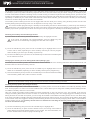
SETTING MENU
D/R
SPEED
CURVE
F/S
BASE
FUNC
PG. 19
PG. 20
PG. 21
PG. 22
PG. 24
PG. 26
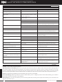
MENU
PAGE #
MENU DESCRIPTION
Adjust Steering, Throttle and Brake Dual Rates
Adjust Servo Speed in the Forward and the Return to Neutral Directions
Adjust Channel Adjustable Rate Control (ARC)
Program Fail Safe Settings and Receiver Battery Voltage Fail Safe
Adjust Channel Servo Reversing, Sub-Trim and End Points
Adjust Channel Trim, Anti-Lock Brake, Throttle Offset and Throttle Type
The following Programming Menus are available within the SETTING menu:
To access the various SETTING menu Programming Menus, turn the transmitter
ON, then press the ENTER key to open the PROGRAMMING screen.
Press the UP or DOWN keys to highlight the SETTING menu, then press the
ENTER key to open the SETTING menu.
SETTING MENU OVERVIEW SETTING
D
/
R MENU
DUAL RATE
SETTING
The Dual Rate function allows you to change the control authority of the Steering, Throttle High Side and Throttle Brake Side
by changing the amount of servo travel relative to control input. For example, by Increasing the Steering Dual Rate, you can
make the Steering servo travel more, which might prevent your model from pushing during turns. Alternately, if your model
over-steers during turns, you can reduce the amount of Steering Dual Rate. Adjusting Steering Dual Rate affects both Right
Side and Left Side steering equally, however, you are able to adjust Throttle Dual Rate on the Throttle High Side and Throttle
Brake Side independently.
IMPORTANT: Prior to programming the Dual Rate function, you should adjust the maximum Left and Right (or High and Low)
End Points. For more information, see the EPA Menu section on pages 25 and 26.
In the default configuration, Trim Switch Trm3 controls Steering Dual
Rate. Throttle and/or Brake Dual Rate can be changed while you're
driving by Assigning these functions to a Trim Switch. In addition, the Dual
Rate function can be toggled ON and OFF while you're driving by assigning
thisfunctiontoanAuxiliarySwitch.Formoreinformation,seetheKEYASSIGN
Menu section on pages 56 through 60.
IMPORTANT: Dual Rate percentage values cannot be changed for A1 (Auxiliary Channel 1) or A2 (Auxiliary Channel 2).
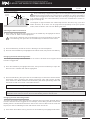
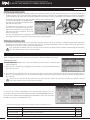
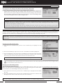
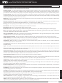
Changing the Dual Rate Percentage Values:
1) From within the SETTING menu, press the UP or DOWN keys to highlight the channel
you want to adjust the Dual Rate percentage value for, then press the ENTER key to
open the D/R menu. RATE 100% will be highlighted.
If the cursor isn't flashing over Channel/Options, press the BACK key.
2) Press the ENTER key, then press the UP or DOWN keys to Increase or Decrease the
Dual Rate percentage value for the selected channel. When the Dual Rate percentage
value is Decreased, servo travel is Decreased. When the Dual Rate percentage value
is Increased, servo travel is Increased.
D/R RATE setting range is 0% to 100%. The default setting for all channels is 100%.

20
MT- S
2.4GHZ FH4T RADIO SYSTEM USER'S GUIDE
TR
Telemetry System with Sanwa Synchronized Link Support
Section Continued on Next Page
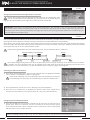
Servo Speed Programming Values can be changed while you're driving by Assigning these functions to a Trim Switch.
In addition, the Servo Speed function can be toggled ON and OFF while you're driving by assigning this function to an
AuxiliarySwitch.Formoreinformation,seetheKEYASSIGNMenusectiononpages56through60.
D
/
R MENU
DUAL RATE
SETTING
The Servo Speed function allows you to slow the transit speed of the Steering, Throttle, Auxiliary 1 and Auxiliary 2 servos. Servo
transit speed can be slowed in both the Forward and the Return to Neutral directions independently.
When driving your model, proper steering and throttle control are vital. For example, lowering the transit speed of the steering
servo can help to limit excessive steering, which will enable you to achieve smoother cornering. In addition, lowering the throttle
servo speed can help to ensure smooth throttle control.
Throttle Servo Speed affects only the Throttle High Side. The Throttle Brake Side is unaffected.
SPEED MENU
SERVO SPEED
SETTING
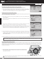
2) Press the BACK key so that the cursor is flashing over Channel/Options.
3) Press the UP or DOWN keys to highlight the desired channel you would like to
change Forward and Return to Neutral values for, then press the ENTER key.
Selecting the Menu and Channel:
1) From within the SETTING menu, press the UP or DOWN keys to highlight the SPEED
menu. SPEED ST FORWARD 0 will be highlighted.
If the cursor is flashing over Channel/Options, press the ENTER key to stop the
cursor flashing, then press the UP or DOWN keys to select the SPEED menu.
Changing the Dual Rate Percentage Values, Continued:
YouareabletoadjusttheDualRatepercentagevaluesfortheThrottleHighSide
and the Throttle Brake Side separately by pressing the UP or DOWN keys to
highlight the selected Rate percentage value, either RATE TH or RATE BR.
IMPORTANT: Dual Rate is a percentage of End Point Adjustment. For example, if you set the Steering Dual Rate
percentage value to 100%, the Steering will travel the same amount defined by your End Point Adjustment programming.
Alternately, if you set the Steering Dual Rate percentage value to 50%, the Steering will travel half the amount defined by your
End Point Adjustment programming.
Steering, Auxililary 1 and Auxiliary 2 Throttle
Changing the Forward Speed Value:
1) Press the ENTER key, then press the DOWN key to Decrease the Forward Servo
Speed value. When 0 is selected, the servo will travel at its normal transit speed
in the Forward direction. When a Negative value is selected, the servo transit speed
will slow down in the Forward direction.
SPEED FORWARD setting range is 0 to -100. The default setting for all channels is 0 (Normal Speed).
Page is loading ...
Page is loading ...
Page is loading ...
Page is loading ...
Page is loading ...
Page is loading ...
Page is loading ...
Page is loading ...
Page is loading ...
Page is loading ...
Page is loading ...
Page is loading ...
Page is loading ...
Page is loading ...
Page is loading ...
Page is loading ...
Page is loading ...
Page is loading ...
Page is loading ...
Page is loading ...
Page is loading ...
Page is loading ...
Page is loading ...
Page is loading ...
Page is loading ...
Page is loading ...
Page is loading ...
Page is loading ...
Page is loading ...
Page is loading ...
Page is loading ...
Page is loading ...
Page is loading ...
Page is loading ...
Page is loading ...
Page is loading ...
Page is loading ...
Page is loading ...
Page is loading ...
Page is loading ...
Page is loading ...
Page is loading ...
Page is loading ...
Page is loading ...
Page is loading ...
Page is loading ...
Page is loading ...
Page is loading ...
Page is loading ...
Page is loading ...
Page is loading ...
Page is loading ...
-
 1
1
-
 2
2
-
 3
3
-
 4
4
-
 5
5
-
 6
6
-
 7
7
-
 8
8
-
 9
9
-
 10
10
-
 11
11
-
 12
12
-
 13
13
-
 14
14
-
 15
15
-
 16
16
-
 17
17
-
 18
18
-
 19
19
-
 20
20
-
 21
21
-
 22
22
-
 23
23
-
 24
24
-
 25
25
-
 26
26
-
 27
27
-
 28
28
-
 29
29
-
 30
30
-
 31
31
-
 32
32
-
 33
33
-
 34
34
-
 35
35
-
 36
36
-
 37
37
-
 38
38
-
 39
39
-
 40
40
-
 41
41
-
 42
42
-
 43
43
-
 44
44
-
 45
45
-
 46
46
-
 47
47
-
 48
48
-
 49
49
-
 50
50
-
 51
51
-
 52
52
-
 53
53
-
 54
54
-
 55
55
-
 56
56
-
 57
57
-
 58
58
-
 59
59
-
 60
60
-
 61
61
-
 62
62
-
 63
63
-
 64
64
-
 65
65
-
 66
66
-
 67
67
-
 68
68
-
 69
69
-
 70
70
-
 71
71
-
 72
72


AIRTRONICS MT-S User manual
- Category
- Remote controlled toys
- Type
- User manual
Ask a question and I''ll find the answer in the document
Finding information in a document is now easier with AI
Related papers
-
AIRTRONICS RX-472 User manual
-
-
-
-
-
-
-
-
-
Other documents
-
 KATUMFEL INDUSTRY LIMITED(HK) XNZ2G4-MA User manual
-
Spektrum TM1100 DSMX Fly-By Aircraft Telemetry Module Operating instructions
-
 Sanwa Electronic Instrument L73-90490 User manual
-
Bartscher 850009 Product information
-
Futaba AZPT3PN-75 User manual
-
 Reely 396209 Operating instructions
-
 Sanwa Electronic Instrument L73-92082 User manual
-
-
Sanwa MT-44 User manual
-
Absima CR4T User manual


