ABB TTH300 Series Operating
- Category
- Measuring & layout tools
- Type
- Operating
This manual is also suitable for

—
ABB MEASUREMENT & ANALYTICS | OPERATING INSTRUCTION
TTH300
Head-mount temperature transmitter
—
ABB Limited
Measurement & Analytics
Howard Road, St. Neots
Cambridgeshire, PE19 8EU
UK
Tel: +44 (0)870 600 6122
Fax: +44 (0)1480 213 339
Email: [email protected]m
ABB Automation Products GmbH
Measurement & Analytics
Schillerstr. 72
32425 Minden
Germany
Tel: +49 571 830-0
Fax: +49 571 830-1806
abb.com/temperature
ABB Inc.
Measurement & Analytics
125 E. County Line Road
Warminster, PA 18974
USA
Tel: +1 215 674 6000
Fax: +1 215 674 7183
Temperature transmitter for all
communications protocols.
Redundancy thanks to two inputs.
Measurement made easy
OI/TTH300-EN Rev. E 02.2019
—
TTH300
Introduction
The TTH300 is available with the HART, PROFIBUS
PA and FOUNDATION Fieldbus communications
protocols.
The TTH300 has global approvals for explosion
protection up to Zone 0.
Safety-relevant applications up to SIL 3
(redundant) are supported in accordance with
IEC 61508.
The TTH300 is approved for custody transfer
measurements through the MID certificate in
accordance with measurement device guideline
2014/32/EU.
Additional Information
Additional documentation on TTH300 is available for
download free of charge at
www.abb.com/temperature.
Alternatively simply scan this code:
—
We reserve the right to make technical changes or modify the contents of this document
without prior notice. With regard to purchase orders, the agreed particulars shall prevail.
ABB does not accept any responsibility whatsoever for potential errors or possible lack of
information in this document.
We reserve all rights in this document and in the subject matter and illustrations contained
therein. Any reproduction, disclosure to third parties or utilization of its contents – in whole or
in parts – is forbidden without prior written consent of ABB.
© ABB 2019 3KXT231001R4201

2 TTH300 HEAD-MOUNT TEMPERATURE TRANSMITTER | OI/TTH300-EN REV. E
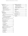
Table of contents
Change from one to tw o columns
1 Safety .......................................................................... 4
General information and instructions .................................. 4
Warnings .................................................................................... 4
Intended use ............................................................................. 5
Improper use ............................................................................. 5
Warranty provisions ................................................................. 5
Notes on data safety ............................................................... 5
Manufacturer’s address .......................................................... 5
2 Use in potentially explosive atmospheres in
accordance with ATEX and IECEx ............................ 6
Ex marking ................................................................................. 6
Transmitter .......................................................................... 6
LCD indicator ....................................................................... 6
Temperature data .................................................................... 7
Transmitter .......................................................................... 7
LCD indicator ....................................................................... 7
Electrical data ........................................................................... 7
Transmitter .......................................................................... 7
LCD indicator ....................................................................... 7
Installation instructions .......................................................... 8
ATEX / IECEx ........................................................................ 8
IP protection rating of housing ........................................ 8
Electrical connections ........................................................ 8
Grounding ............................................................................. 8
Intrinsic safety installation check .................................... 8
Installation in a potentially explosive atmosphere ....... 9
Commissioning....................................................................... 11
Operating instructions .......................................................... 11
Protection against electrostatic discharges ................ 11
3 Use in potentially explosive atmospheres in
accordance with FM and CSA ................................. 12
Ex marking ............................................................................... 12
Transmitter ........................................................................ 12
LCD indicator ..................................................................... 12
Installation instructions ........................................................ 13
FM / CSA ............................................................................. 13
IP protection rating of housing ...................................... 13
Electrical connections ...................................................... 13
Commissioning....................................................................... 14
Operating instructions .......................................................... 14
Protection against electrostatic discharges ................ 14
4 Design and function ................................................ 15
Input functionality ................................................................. 15
Sensor Redundancy .......................................................... 15
Sensor drift monitoring ................................................... 15
Sensor error adjustment in accordance with Callendar-
Van Dusen ........................................................................... 16
5 Product identification ............................................ 16
Name plate .............................................................................. 16
6 Transport and storage ............................................ 17
Inspection ................................................................................ 17
Transporting the device ........................................................ 17
Storing the device ................................................................... 17
Ambient conditions ........................................................... 17
Returning devices ................................................................... 17
7 Installation ................................................................ 18
Ambient conditions ............................................................... 18
Installation options ............................................................... 18
Installation on the measuring inset ............................... 18
Installation in the cover of the connection head ........ 19
Installation on the top-hat rail........................................ 19
Installing / removing the optional LCD indicator ............ 19
Disassembling the LCD indicator .................................. 19
Installing the LCD indicator ............................................ 19
Rotating the LCD indicator ............................................. 19
8 Electrical connections ............................................ 20
Safety instructions ................................................................ 20
Protection of the transmitter from damage caused by
highly energetic electric interferences .............................. 20
Suited protective measures ............................................. 21
Conductor material ................................................................ 21
Pin assignment ....................................................................... 22
Resistance thermometers (RTD) / resistors
(potentiometer) ................................................................ 22
Thermocouples / voltages and resistance
thermometer (RTD) / thermocouple combinations ... 23
Electrical data for inputs and outputs ............................... 24
Input - resistance thermometer / resistances ............ 24
Input - thermocouples / voltages .................................. 24
Functionality input ........................................................... 24
Output – HART® ................................................................. 25
Output – PROFIBUS PA® .................................................. 25
Output – FOUNDATION Fieldbus® ................................. 26
Power supply ..................................................................... 26
9 MID Certification ..................................................... 28
TTH300 with MID Certification ........................................... 28
General ................................................................................ 28
Areas of application, conditions and requirements ... 28
Installation and Operation .............................................. 28

TTH300 HEAD-MOUNT TEMPERATURE TRANSMITTER | OI/TTH300-EN REV. E 3
10 Commissioning ........................................................ 29
General ..................................................................................... 29
Checks prior to commissioning .......................................... 29
Communication ...................................................................... 29
HART® Communication .................................................... 29
Operating modes .............................................................. 29
Configuration options / tools......................................... 29
Diagnosis notice ................................................................ 29
PROFIBUS® Communication........................................... 30
Voltage / current consumption ..................................... 30
FOUNDATION Fieldbus® Communication ................... 30
Voltage / current consumption ..................................... 30
Basic Setup .............................................................................. 31
11 Operation ................................................................. 31
Safety instructions ................................................................. 31
Hardware settings ................................................................. 31
Menu navigation ..................................................................... 32
HART® menu levels ............................................................ 33
PROFIBUS PA® and FOUNDATION Fieldbus® H1 menu
levels .................................................................................... 33
Process display ....................................................................... 34
Error messages on the HART® LCD display .................. 34
Error messages on the PROFIBUS PA® and
FOUNDATION Fieldbus® LCD display ............................ 35
Switching to the information level ...................................... 35
Switching to the configuration level (parameterization)
36
Selecting and changing parameters ................................... 36
Entry from table................................................................. 36
HART® Parameter Overview ................................................. 38
Parameter description HART® ............................................ 40
Menu: Device Setup .......................................................... 40
Menu: Device Info .............................................................. 43
Menu: Display ..................................................................... 43
Menu: Process Alarm ....................................................... 44
Menu: Communication .................................................... 44
Menu: Calibrate ................................................................. 44
Menu: Diagnosis ............................................................... 45
Activating write protection ............................................ 45
Deactivating write protection ....................................... 45
PROFIBUS PA® und FOUNDATION Fieldbus® Parameter
overview .................................................................................. 46
Parameter description PROFIBUS PA® and
FOUNDATION Fieldbus® ...................................................... 48
Menu: Device Setup .......................................................... 48
Menu: Device Info ............................................................. 50
Menu: Communication .................................................... 50
Menu: Service Menu .......................................................... 51
Menu: Display ..................................................................... 52
Menu: Calibrate .................................................................. 52
Factory settings ..................................................................... 53
Firmware settings ............................................................. 53
12 Diagnosis / error messages .................................. 54
Diagnostic information ........................................................ 54
Monitoring of operating data ......................................... 54
Operating hours statistics .............................................. 54
Calling up the error description .......................................... 55
Possible error messages – HART® ...................................... 56
Possible error messages – PROFIBUS PA® and
FOUNDATION Fieldbus® ....................................................... 58
13 Maintenance ............................................................ 59
Safety instructions ................................................................ 59
Cleaning ................................................................................... 59
14 Repair ....................................................................... 59
Safety instructions ................................................................ 59
Returning devices .................................................................. 59
15 Recycling and disposal ........................................... 60
16 Specification ........................................................... 60
17 Additional documents ............................................ 60
18 Appendix ................................................................... 61
Return form ............................................................................. 61

4 TTH300 HEAD-MOUNT TEMPERATURE TRANSMITTER | OI/TTH300-EN REV. E
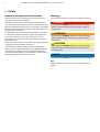
1 Safety
General information and instructions
These instructions are an important part of the product and
must be retained for future reference.
Installation, commissioning, and maintenance of the product
may only be performed by trained specialist personnel who have
been authorized by the plant operator accordingly. The specialist
personnel must have read and understood the manual and must
comply with its instructions.
For additional information or if specific problems occur that are
not discussed in these instructions, contact the manufacturer.
The content of these instructions is neither part of nor an
amendment to any previous or existing agreement, promise or
legal relationship.
Modifications and repairs to the product may only be performed
if expressly permitted by these instructions.
Information and symbols on the product must be observed.
These may not be removed and must be fully legible at all times.
The operating company must strictly observe the applicable
national regulations relating to the installation, function testing,
repair and maintenance of electrical products.
Warnings
The warnings in these instructions are structured as follows:
DANGER
The signal word ‘DANGER’ indicates an imminent danger.
Failure to observe this information will result in death or
severe injury.
WARNING
The signal word ‘WARNING’ indicates an imminent danger.
Failure to observe this information may result in death or
severe injury.
CAUTION
The signal word ‘CAUTION’ indicates an imminent danger.
Failure to observe this information may result in minor or
moderate injury.
NOTICE
The signal word
‘
NOTIC
E
’
indicates possible material damage.
Note
‘Note’ indicates useful or important information about the
product.

TTH300 HEAD-MOUNT TEMPERATURE TRANSMITTER | OI/TTH300-EN REV. E 5
Intended use
This device is intended for the following uses:
• To measure the temperature of fluid, pulpy or pasty
substances and gases or resistance/voltage values.
The device has been designed for use exclusively within the
technical limit values indicated on the name plate and in the data
sheets.
• The maximum ambient temperature must not be exceeded.
• The IP rating of the housing must be observed during
operation.
• For use in potentially explosive atmospheres, follow the
associated guidelines.
• When using as a SIL-device in safety-relevant applications,
the SIL Safety Manual should be observed.
Improper use
The following are considered to be instances of especially
improper use of the device:
• Material application, for example by painting over the
housing, name plate or welding/soldering on parts.
• Material removal, for example by spot drilling the
housing.
Warranty provisions
Using the device in a manner that does not fall within the scope
of its intended use, disregarding this manual, using
underqualified personnel, or making unauthorized alterations
releases the manufacturer from liability for any resulting
damage. This renders the manufacturer's warranty null and void.
Notes on data safety
This product is designed to be connected to and to
communicate information and data via a network interface.
It is operator’s sole responsibility to provide and continuously
ensure a secure connection between the product and your
network or any other network (as the case may be).
Operator shall establish and maintain any appropriate measures
(such as but not limited to the installation of firewalls,
application of authentication measures, encryption of data,
installation of anti-virus programs, etc.) to protect the product,
the network, its system and the interface against any kind of
security breaches, unauthorized access, interference, intrusion,
leakage and / or theft of data or information.
ABB Automation Products GmbH and its affiliates are not liable
for damages and / or losses related to such security breaches,
any unauthorized access, interference, intrusion, leakage and /
or theft of data or information.
Manufacturer’s address
ABB Automation Products GmbH
Measurement & Analytics
Schillerstr. 72
32425 Minden
Germany
Tel: +49 571 830-0
Fax: +49 571 830-1806
Customer service center
Tel: +49 180 5 222 580
Email: [email protected]

6 TTH300 HEAD-MOUNT TEMPERATURE TRANSMITTER | OI/TTH300-EN REV. E
Change from two to one column
2 Use in potentially explosive atmospheres in accordance with
ATEX and IECEx
Change from one to tw o columns
Note
• Further information on the approval of devices for use in
potentially explosive atmospheres can be found in the
explosion protection test certificates (at
www.abb.com/temperature).
• Depending on the design, a specific marking in accordance
with ATEX or IECEx applies.
Ex marking
Transmitter
ATEX intrinsic safety
The device fulfills the requirements of Directive 2014/34/EU in
case of corresponding purchase orders and is approved for use
in Zone 0, 1 and 2.
Model TTH300-E1H
Type Examination Test Certificate PTB 05 ATEX 2017 X
II 1 G Ex ia IIC T6 Ga
II 2 (1) G Ex [ia IIC Ga] ib IIC T6 Gb
II 2 G (1D) Ex [ia IIIC Da] ib IIC T6 Gb
Model TTH300-E1P and TTH300-E1F
Type Examination Test Certificate PTB 09 ATEX 2016 X
II 1 G Ex ia IIC T6 Ga
II 2 (1) G Ex [ia IIC Ga] ib IIC T6 Gb
II 2 G (1D) Ex [ia IIIC Da] ib IIC T6 Gb
Non-sparking ATEX
The device fulfills the requirements of Directive 2014/34/EU in
case of corresponding purchase orders and is approved for use
in Zone 2.
Model TTH300-E2X
Declaration of conformity
II 3 G Ex nA IIC T1-T6 Gc
IECEx intrinsic safety
Approved for use in Zone 0, 1, and 2.
Model TTH300-H1H
IECEx certificate of conformity IECEx PTB 09.0014X
Model TTH300-H1P and TTH300-H1F
IECEx certificate of conformity IECEx PTB 11.0108X
Ex ia IIC T6...T1 Ga
Ex [ia IIC Ga] ib IIC T6...T1 Gb
Ex [ia IIIC Da] ib IIC T6...T1 Gb
LCD indicator
ATEX intrinsic safety
The device fulfills the requirements of Directive 2014/34/EU in
case of corresponding purchase orders and is approved for use
in Zone 0, 1 and 2.
Type Examination Test Certificate PTB 05 ATEX 2079 X
II 1G Ex ia IIC T6 Ga
Non-sparking ATEX
The device fulfills the requirements of Directive 2014/34/EU in
case of corresponding purchase orders and is approved for use
in Zone 2.
Declaration of conformity
II 3 G Ex nA IIC T1-T6 Gc
IECEx intrinsic safety
Approved for use in Zone 0, 1, and 2.
IECEx certificate of conformity IECEx PTB 12.0028X
Ex ia IIC T6

TTH300 HEAD-MOUNT TEMPERATURE TRANSMITTER | OI/TTH300-EN REV. E 7
Temperature data
Transmitter
ATEX/IECEx intrinsic safety, non-sparking ATEX
Temperature class Permissible ambient temperature range
Device category 1 use Device category 2 / 3 use
T6 −50 to 44 °C
(−58 to 111.2 °F)
−50 to 56 °C
(−58 to 132.8 °F)
T5 −50 to 56 °C
(−58 to 132.8 °F)
−50 to 71 °C
(−58 to 159.8 °F)
T4-T1 −50 to 60 °C
(−58 to 140.0 °F)
−50 to 85 °C
(−58 to 185.0 °F)
LCD indicator
ATEX/IECEx intrinsic safety, non-sparking ATEX
Temperature class Permissible ambient temperature range
Device category 1 use Device category 2 / 3 use
T6 −40 to 44 °C
(−40 to 111.2 °F)
−40 to 56 °C
(−40 to 132.8 °F)
T5 −40 to 56 °C
(−40 to 132.8 °F)
−40 to 71 °C
(−40 to 159.8 °F)
T4-T1 −40 to 60 °C
(−40 to 140 °F)
−40 to 85 °C
(−40 to 185 °F)
Electrical data
Transmitter
Intrinsic safety type of protection Ex ia IIC (part 1)
Power supply circuit*
TTH300-E1H
TTH300-H1H
TTH300-E1P/-H1P
TTH300-E1F/-H1F
FISCO* ENTITY
Max. voltage U
i
= 30
V
U
i
≤ 17.5 V U
i
≤ 24.0 V
Short-circuit current I
i
= 130 m
A
I
i
≤ 183 mA
**
I
i
≤ 250 mA
Max. power P
i
= 0.8
W
P
i
≤ 2.56 W
**
P
i
≤ 1.2 W
Internal inductance L
i
= 0.5 mH L
i
≤ 10 μHL
i
≤ 10 μH
Internal capacitance C
i
= 0.57 nF
***
C
i
≤ 5 nF C
i
≤ 5 nF
* FISCO in accordance with 60079-27
** II B FISCO: Ii ≤ 380 mA, Pi ≤ 5.32 W
*** Only applies for HART variants. From HW Rev. 1.07, previously 5 nF
Intrinsic safety type of protection Ex ia IIC (part 2)
Measurement current circuit
Resistance
thermometers, resistors
Thermocouples, voltages
Max. voltage U
o
= 6.5 V U
o
= 1.2 V
Short-circuit current I
o
= 25 mA I
o
= 50 mA
Max. power P
o
= 38 mW P
o
= 60 mW
Internal inductance L
i
= 0 mH L
i
= 0 mH
Internal capacitance C
i
= 49 nF C
i
= 49 nF
Maximum permissible
external inductance
L
o
= 5 mH L
o
= 5 mH
Maximum permissible
external capacitance
C
o
= 1.55 μFC
o
= 1.05 μF
Intrinsic safety type of protection Ex ia IIC (part 3)
LCD indicator interface
Max. voltage U
o
= 6.2
V
Short-circuit current I
o
= 65.2 m
A
Max. power P
o
= 101 m
W
Internal inductance L
i
= 0 mH
Internal capacitance C
i
= 0 nF
Maximum permissible external inductance L
o
= 5 mH
Maximum permissible external capacitance C
o
= 1.4 μF
LCD indicator
Intrinsic safety type of protection Ex ia IIC
Supply circuit
Max. voltage U
i
= 9 V
Short-circuit current I
i
= 65.2 mA
Max. power P
i
= 101 mW
Internal inductance L
i
= 0 mH
Internal capacitance C
i
= 0 nF

8 TTH300 HEAD-MOUNT TEMPERATURE TRANSMITTER | OI/TTH300-EN REV. E
… 2 Use in potentially explosive atmospheres in accordance with
ATEX and IECEx
Installation instructions
ATEX / IECEx
The installation, commissioning, maintenance and repair of
devices in potentially explosive atmospheres must only be
carried out by appropriately trained personnel. Works may be
carried out only by persons, whose training has included
instructions on different types of protection and installation
techniques, concerned rules and regulations as well as general
principles of zoning. The person must possess the appropriate
competences for the type of work to be conducted.
When operating with combustible dusts, comply with
EN 60079-31.
The safety instructions for electrical apparatus in potentially
explosive areas must be in accordance with Directive
2014/34/EU (ATEX) and IEC 60079-14 (Installation of electrical
equipment in potentially explosive areas).
Comply with the applicable regulations for the protection of
employees to ensure safe operation.
IP protection rating of housing
The temperature transmitter and LCD indicator Type A and
Type AS must be installed such that an IP rating of at least IP 20
is achieved in accordance with IEC 60529.
Electrical connections
Grounding
If, for functional reasons, the intrinsically safe circuit needs to be
grounded by means of a connection to the potential
equalization, it may only be grounded at one point.
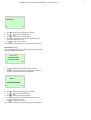
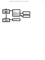
Intrinsic safety installation check
If transmitters are operated in an intrinsically safe circuit, proof
that the interconnection is intrinsically safe must be provided in
accordance with IEC/EN 60079-14 as well as IEC/EN 60079-25.
The supply isolators / DCS inputs must feature intrinsically safe
input protection circuits in order to eliminate hazards (spark
formation).
In order to provide proof of intrinsic safety, the electrical limit
value must be used as the basis for the EC-type examination
certificates for the equipment (devices); this includes the
capacitance and inductance values of the cables.
Proof of intrinsic safety is said to have been provided if the
following conditions are fulfilled when a comparison is carried
out in relation to the limit values of the equipment:
Transmitter
(intrinsically safe equipment)
Supply isolator / DCS input
(related equipment)
U
i
≥ U
o
I
i
≥ I
o
P
i
≥ P
o
L
i
+ L
c
(cable) ≤ L
o
C
i
+ C
c
(cable) ≤ C
o
Field (Ex area) Control room (safe area)
A Transmitter B Supply isolator / DCS input with
supply / segment coupler
Figure 1: Intrinsic safety installation check

TTH300 HEAD-MOUNT TEMPERATURE TRANSMITTER | OI/TTH300-EN REV. E 9
Installation in a potentially explosive atmosphere
Transmitters can be installed in all kinds of industrial sectors.
Potentially explosive systems are divided into zones,
meaning that a wide range of different instruments are also
required. For this, pay attention to the country-specific
guidelines and certificates!
Note
Ex relevant specifications must be taken from the EC-type
examination certificates and other relevant certificates that
apply in each case.
With transmitters for PROFIBUS PA and FOUNDATION
Fieldbus H1 applications, FISCO interconnection methods can be
used.
ATEX – Zone 0
Designation: II 1 G Ex ia IIC T6 Ga
Ex area Zone 0 Safe area
A Sensor
B Transmitter in housing with IP-rating
IP 20
C Supply isolator [Ex ia]
D Interface for LCD indicator
Figure 2: Hookup in ATEX – Zone 0
When using the transmitter in Zone 0, it must be installed in a
suitable housing with IP rating IP 20.
The input for the supply isolator must be designed with ‘Ex ia’
type of protection.
When using the transmitter in Zone 0, make sure that
impermissible electrostatic charging of the transmitter is
avoided (observe the warnings on the device).
As the user, it is your responsibility to ensure that the sensor
instrumentation meets the requirements of applicable explosion
protection standards.
Note
When operating the transmitter in Zone 0 (EPL ‘Ga’), the
compatibility of the device materials with the surrounding
atmosphere must be ensured.
Encapsulation material used for the transmitter:
Polyurethane (PUR), WEVO PU-417
ATEX – Zone 1 (0)
Marking: II 2 (1) G Ex [ia IIC Ga] ib IIC T6 Gb
Zone 0 or 1
Ex area Zone 1 Safe area
A Sensor
B Transmitter in housing with IP
rating IP 20
C Supply isolator [Ex ib]
D Interface for LCD indicator
Figure 3: Hookup in ATEX - Zone 1 (0)
When using the transmitter in Zone 1, it must be installed in a
suitable housing with IP -rating IP 20.
The input for the supply isolator must be designed with ‘Ex ib’
type of protection.
As the user, it is your responsibility to ensure that the sensor
instrumentation meets the requirements of applicable explosion
protection standards. The sensor can be installed in Zone 1 or
Zone 0.
When using the transmitter in Zone 1, you must ensure that
impermissible electrostatic charging of the temperature
transmitter is prevented (observe the warnings on the device).

10 TTH300 HEAD-MOUNT TEMPERATURE TRANSMITTER | OI/TTH300-EN REV. E
… 2 Use in potentially explosive atmospheres in accordance with
ATEX and IECEx
… Installation instructions
ATEX – Zone 1 (20)
Marking: II 2 G (1D) Ex [ia IIIC Da] ib IIC T6 Gb
Zone 20 or
21
Ex area Zone 1 Safe area
A Sensor
B Transmitter in housing with IP
rating IP 20
C Supply isolator [Ex ib]
D Interface for LCD indicator
Figure 4: Hookup in ATEX - Zone 1 (20)
When using the transmitter in Zone 1, it must be installed in a
suitable housing with IP -rating IP 20.
The input for the supply isolator must be designed with ‘Ex ib’
type of protection.
As the user, it is your responsibility to ensure that the sensor
instrumentation meets the requirements of applicable explosion
protection standards. The sensor can be installed in Zone 20 or
Zone 21.
When using the transmitter in Zone 1, make sure that
impermissible electrostatic charging of the temperature
transmitter is avoided (observe the warnings on the device).
ATEX – Zone 2
Designation: II 3 G Ex nA IIC T1-T6 Gc
Ex area Zone 2 Safe area
A Sensor
B Transmitter in housing with IP
rating IP 54
C Supply isolator
D Interface for LCD indicator
Figure 5: Hookup in ATEX – Zone 2
When using the transmitter in Zone 2, observe the following:
• The temperature transmitter must be installed in its own
housing. This housing must at least meet IP rating IP 54
(in accordance with EN 60529) and other requirements
for potentially explosive atmosphere (e.g. a certified
housing).
• External measures must be made for the power supply
circuit in order to prevent the rated voltage from being
up-scaled by more than 40 % in the event of transient
disturbances.
• The electrical connections must only be opened or closed
when there is no hazardous atmosphere.
• When using the transmitter in Zone 2, make sure that
impermissible electrostatic charging of the temperature
transmitter is prevented (observe the warnings on the
device).

TTH300 HEAD-MOUNT TEMPERATURE TRANSMITTER | OI/TTH300-EN REV. E 11
Commissioning
The commissioning and parameterization of the device may also
be carried out in potentially explosive atmospheres using a
handheld terminal that has been approved accordingly under
consideration of an intrinsic safety installation check.
Alternatively, an Ex modem can be connected to the circuit
outside the potentially explosive atmosphere.
Operating instructions
Protection against electrostatic discharges
The plastic parts inside the device can store electrostatic
charges.
Make sure that no electrostatic charges can accumulate when
handling the device.

12 TTH300 HEAD-MOUNT TEMPERATURE TRANSMITTER | OI/TTH300-EN REV. E
Change from two to one column
3 Use in potentially explosive atmospheres in accordance with FM and CSA
Change from one to tw o columns
Note
• Further information on the approval of devices for use in
potentially explosive atmospheres can be found in the
explosion protection test certificates (at
www.abb.com/temperature).
• Depending on the design, a specific marking in accordance
with FM or CSA applies.
Ex marking
Transmitter
FM Intrinsically Safe
Model TTH300-L1H
Control Drawing SAP_214829
Model TTH300-L1P
Control Drawing TTH300-L1P (IS)
Model TTH300-L1F
Control Drawing TTH300-L1F (IS)
Class I, Div. 1 + 2, Groups A, B, C, D
Class I, Zone 0, AEx ia IIC T6
FM Non-Incendive
Model TTH300-L2H
Control Drawing 214831 (Non-Incendive)
Model TTH300-L2P
Control Drawing TTH300-L2P (NI_PS)
TTH300-L2P (NI_AA)
Model TTH300-L2F
Control Drawing TTH300-L2F (NI_PS)
TTH300-L2F (NI_AA)
Class I, Div. 2, Groups A, B, C, D
CSA Intrinsically Safe
Model TTH300-R1H
Control Drawing 214826
Model TTH300-R1P
Control Drawing TTH300-R1P (IS)
Model TTH300-R1F
Control Drawing TTH300-R1F (IS)
Class I, Div. 1 + 2, Groups A, B, C, D
Class I, Zone 0, Ex ia Group IIC T6
CSA Non-Incendive
Model TTH300-R2H
Control Drawing SAP_214824 (Non-Incendive)
SAP_214896 (Non-Incendive)
Model TTH300-R2P
Control Drawing TTH300-R2P (NI_PS)
TTH300-R2P (NI_AA)
Model TTH300-R2F
Control Drawing TTH300-R2F (NI_PS)
TTH300-R2F (NI_AA)
Class I, Div. 2, Groups A, B, C, D
LCD indicator
FM Intrinsically Safe
Control Drawing SAP_214 748
I.S. Class I Div 1 and Div 2, Group: A, B, C, D or
I.S. Class I Zone 0 AEx ia IIC T*
U
i
/ V
max
= 9 V, I
i
/ I
max
< 65.2 mA, P
i
= 101 mW, C
i
= 0.4 μF, L
i
= 0
FM Non-Incendive
Control Drawing SAP_214 751
N.I. Class I Div 2, Group: A, B, C, D oder Ex nL IIC T**, Class I Zone 2
U
i
/ V
max
= 9 V, I
i
/ I
max
< 65.2 mA, P
i
= 101 mW, C
i
= 0.4 μF, L
i
= 0
CSA Intrinsically Safe
Control Drawing SAP_214 749
I.S. Class I Div 1 and Div 2; Group: A, B, C, D or
I.S Zone 0 Ex ia IIC T*
U
i
/ V
max
= 9 V, I
i
/ I
max
< 65.2 mA, P
i
= 101 mW, C
i
< 0.4 μF, L
i
= 0
CSA Non-Incendive
Control Drawing SAP_214 750
N.I. Class I Div 2, Group: A, B, C, D oder Ex nL IIC T**, Class I Zone 2
U
i
/ V
max
= 9 V, I
i
/ I
max
< 65.2 mA, P
i
= 101 mW, C
i
< 0.4 μF, L
i
= 0
* Temp. Ident: T6 T
amb
56 °C, T4 T
amb
85 °C
** Temp. Ident: T6 T
amb
60 °C, T4 T
amb
85 °C

TTH300 HEAD-MOUNT TEMPERATURE TRANSMITTER | OI/TTH300-EN REV. E 13
Installation instructions
FM / CSA
The installation, commissioning, maintenance and repair of
devices in areas with explosion hazard must only be carried out
by appropriately trained personnel.
The operator must strictly observe the applicable national
regulations with regard to installation, function tests, repairs,
and maintenance of electrical devices. (e. g. NEC, CEC).
IP protection rating of housing
The temperature transmitter and LCD indicator Type A and
Type AS must be installed such that an IP rating of at least IP 20
is achieved in accordance with IEC 60529.
Electrical connections
Grounding
If, for functional reasons, the intrinsically safe circuit needs to be
grounded by means of a connection to the potential
equalization, it may only be grounded at one point.
Intrinsic safety installation check
If transmitters are operated in an intrinsically safe circuit, proof
that the interconnection is intrinsically safe must be provided in
accordance with IEC/EN 60079-14 as well as IEC/EN 60079-25.
The supply isolators / DCS inputs must feature intrinsically safe
input protection circuits in order to eliminate hazards (spark
formation).
In order to provide proof of intrinsic safety, the electrical limit
value must be used as the basis for the EC-type examination
certificates for the equipment (devices); this includes the
capacitance and inductance values of the cables.
Proof of intrinsic safety is said to have been provided if the
following conditions are fulfilled when a comparison is carried
out in relation to the limit values of the equipment:
Transmitter
(intrinsically safe equipment)
Supply isolator / DCS input
(related equipment)
U
i
≥ U
o
I
i
≥ I
o
P
i
≥ P
o
L
i
+ L
c
(cable) ≤ L
o
C
i
+ C
c
(cable) ≤ C
o
Field (Ex area) Control room (safe area)
A10096-01
AB
+
-
+
-
A Transmitter
B Supply isolator / DCS input with
supply / Segment coupler
Figure 6: Intrinsic safety installation check
Installation in a potentially explosive atmosphere
Transmitters can be installed in all kinds of industrial sectors.
Potentially explosive systems are divided into zones,
meaning that a wide range of different instruments are also
required. For this, pay attention to the country-specific
guidelines and certificates!
Note
Ex relevant specifications must be taken from the EC-type
examination certificates and other relevant certificates that
apply in each case.
With transmitters for PROFIBUS PA and FOUNDATION
Fieldbus H1 applications, FISCO interconnection methods can be
used.

14 TTH300 HEAD-MOUNT TEMPERATURE TRANSMITTER | OI/TTH300-EN REV. E
… 3 Use in potentially explosive atmospheres in accordance with FM and CSA
Commissioning
The commissioning and parameterization of the device may also
be carried out in potentially explosive atmospheres using a
handheld terminal that has been approved accordingly under
consideration of an intrinsic safety installation check.
Alternatively, an Ex modem can be connected to the circuit
outside the potentially explosive atmosphere.
Operating instructions
Protection against electrostatic discharges
The plastic parts inside the device can store electrostatic
charges.
Make sure that no electrostatic charges can accumulate when
handling the device.

TTH300 HEAD-MOUNT TEMPERATURE TRANSMITTER | OI/TTH300-EN REV. E 15
4 Design and function
Digital transmitters are communication-ready devices with
microprocessor-controlled electronics. They conform to the
requirements of IP rating IP 20 and are suited for integration
into DIN A and DIN B sensor heads.
With HART® transmitters, an FSK signal is superimposed on the
4 to 20 mA output signal in accordance with the HART standard
to facilitate bidirectional communication.
With PROFIBUS PA® transmitters, communication takes place in
accordance with PROFIBUS-MBP (IEC 61158-2), PROFIBUS PA
Profile 3.01.
With FOUNDATION Fieldbus® transmitters, communication
takes place in accordance with the FOUNDATION Fieldbus H1
(IEC 61158-2), ITK Version 5.x.
The transmitters can be configured, polled, and tested using a
DTM or an EDD.
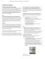
As an option, the transmitter can be fitted with a type A or a type
AS LCD indicator. Type AS is used exclusively for visualizing
current process values. Type A also supports the option of
configuring the transmitter. It is recommended that you use this
combination.
The electrical connection between the LCD display and
transmitter is provided by a 6-pin flat ribbon cable with a plug
connector. The LCD display can only be operated when
connected to transmitters that have an LCD display interface.
Input functionality
Sensor Redundancy
To enhance system availability, the TTH300 has two sensor
inputs.
The second sensor input can be used redundantly for both
resistance thermometers (2 x three-wire circuit or 2 x two-wire
circuit) and thermocouples, or for a mixture of the two.
Sensor redundancy (or sensor backup) always involves
measuring the temperature of the two sensors and calculating
the mean value on the basis of this.
This value is provided at the output of the transmitter. Should a
sensor fail, the temperature measurement for the sensor that
remains in operation is provided at the output of the
transmitter.
A relevant diagnosis notice is available via DTM, EDD,
FDI Package (FIM) or on the LCD indicator. The measured value
remains available and maintenance measures can be taken at the
same time.
Sensor drift monitoring
When two sensors are connected, sensor drift monitoring can be
activated via the DTM, EDD or FDI Package (FIM).
The sensor drift monitoring can be activated for the following
sensor types:
• 2 × resistance thermometer (RTD), two-wire circuit
• 2 × resistance thermometer (RTD), three-wire circuit
• 2 × resistors (potentiometer), two-wire circuit
• 2 × resistors (potentiometer), three-wire circuit
• 2 × thermocouple
• 2 × voltages
• 1 × resistance thermometer (RTD), two-wire circuit, and
1 × thermocouple
• 1 × resistance thermometer (RTD), three-wire circuit, and
1 × thermocouple
• 1 × resistance thermometer (RTD), four-wire circuit, and
1 × thermocouple
To activate sensor drift monitoring, the transmitter must first
be configured for the sensor types referred to above. Following
this, the maximum permissible sensor deviation must be
configured, e.g., 1 K.
Since sensor response times may differ slightly, it is then
necessary to configure a limit time period during which the
sensor deviation has to constantly exceed the maximum set.
If the transmitter records a larger sensor deviation during the
defined time period, a ‘Maintenance required’ diagnosis
information is generated through HART, EDD and DTM in
accordance with NE 107. At the same time, diagnostic
information is shown on the LCD indicator.

16 TTH300 HEAD-MOUNT TEMPERATURE TRANSMITTER | OI/TTH300-EN REV. E
… 4 Design and function
… Input functionality
If drift monitoring is used for the same types of sensor
(2 × Pt100 or 2 × thermocouple), the mean value calculated from
the two sensors is mapped to the transmitter output signal as a
process variable in redundancy mode.
If a thermocouple is used for Pt100 drift monitoring, the Pt100
sensor (see Resistance thermometers (RTD) / resistors
(potentiometer) on page 22) should be connected to channel 1
and the thermocouple to channel 2.
The measured value from channel 1 (Pt100) is mapped to the
transmitter output as a process variable.
Note
Before configuring the maximum permissible sensor deviation
for drift monitoring, sensor adjustment with respect to the
sensor channel 1 value must be carried out with the help of,
for example. the TTH300 DTM.
Sensor error adjustment in accordance with Callendar-
Van Dusen
Under normal circumstances, the standard Pt100 characteristic
curve is used for resistance thermometer measurement.
However, recent advances in technology now mean that
maximum measuring accuracy can be achieved where necessary
by carrying out individual sensor error adjustment.
Sensor characteristic curves are optimized by using a Pt100
polynomial in accordance with IST-90 / IEC 751, and EN 60150,
and by applying A ,B, C, or Callendar-Van Dusen coefficients.
With the help of the DTM, EDD or FDI package (FIM), these
sensor coefficients (Callendar-Van Dusen) can be adjusted and
stored in the transmitter as a CVDcharacteristic curve. Up to five
different CVDcharacteristic curves can be stored for HART and
PROFIBUS PA, while up to two CVDcharacteristic curves can be
stored for FOUNDATION Fieldbus.
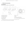
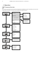
5 Product identification
Name plate
Note
Products that are marked with the adjacent symbol
may not be disposed of as unsorted municipal waste
(domestic waste).
They should be disposed of through separate
collection of electric and electronic devices.
Note
The ambient temperature range
n
provided on the name plate
refers only to the transmitter itself and not to the sensor
element used in the measuring inset.
For devices with PROFIBUS PA or FOUNDATION Fieldbus, the
device-ID is also specified.
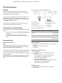
1 Manufacturer, manufacturer address, manufacturing year - week
2 Safety integrity level, SIL logo (optional with HART transmitter)
3 CE mark (EU conformity), if not on additional plate
4 Type designation / model
5 Transmitter communications protocol (HART, FF, PA)
6 2D barcode for serial number in accordance with order
7 7-digit serial number of the device electronic unit
8 Software revision
9 Hardware version
0 ‘Follow product documentation’ symbol
k l m
HART transmitter:
k Set measuring range of the transmitter
l Measuring point tag (TAG) in accordance with order (optional)
m Set sensor type and circuit type
l m Transmitter FOUNDATION Fieldbus or PROFIBUS PA:
l Measuring point tag (TAG) in accordance with order (optional)
m DEVICE_ID or Ident_Number
n Ambient temperature range, on additional plate for Ex versions
o Transmitter specification (supply voltage range, output current range,
communications protocol)
p Coding of the type of protection of the device (in accordance with
ordering information)
q Serial number of the device (serial number in accordance with order)
Figure 7: HART name plate (example)

TTH300 HEAD-MOUNT TEMPERATURE TRANSMITTER | OI/TTH300-EN REV. E 17
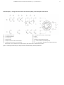
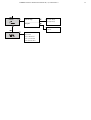
Figure 8: PROFIBUS PA name plate (example)
Figure 9: FOUNDATION Fieldbus name plate (example)
Devices with an explosion-proof design are marked with the
following special data plate.
1 Type designation in accordance
with approval
2 Type designation
3 Temperature class of the
explosion-proof design
4 CE-mark (EU conformity) and
notified body for quality
assurance
5 Ex-marking
6 IP rating explosion-proof design
Figure 10: Additional plate for explosion-protected apparatus (example)
Note
The name plates displayed are examples. The device
identification plates affixed to the device can differ from this
representation.
6 Transport and storage
Inspection
Check the devices immediately after unpacking for possible
damage that may have occurred from improper transport.
Details of any damage that has occurred in transit must be
recorded on the transport documents.
All claims for damages must be submitted to the shipper
without delay and before installation.
Transporting the device
Observe the following instructions:
• Do not expose the device to humidity during transport.
Pack the device accordingly.
• Pack the device so that it is protected against vibrations
during transport, for example, by using air-cushioned
packing.
Storing the device
Bear the following points in mind when storing devices:
• Store the device in its original packaging in a dry and
dust-free location.
• Observe the permitted ambient conditions for transport
and storage.
• Avoid storing the device in direct sunlight.
• In principle, the devices may be stored for an unlimited
period. However, the warranty conditions stipulated in
the order confirmation of the supplier apply.
Ambient conditions
The ambient conditions for the transport and storage of the
device correspond to the ambient conditions for operation of
the device.
Adhere to the device data sheet!
Returning devices
For the return of devices, follow the instructions in Repair on
page 59.

18 TTH300 HEAD-MOUNT TEMPERATURE TRANSMITTER | OI/TTH300-EN REV. E
7 Installation
DANGER
Improper installation and commissioning of the device
carries a risk of explosion.
For use in potentially explosive atmospheres, observe the
information in Use in potentially explosive atmospheres in
accordance with ATEX and IECEx on page 6 and Use in
potentially explosive atmospheres in accordance with FM
and CSA on page 12!
Ambient conditions
Ambient temperature
• Standard: −40 to 85 °C (−40 to 185 °F)
• Optional: −50 to 85 °C (−58 to 185 °F)
• Restricted range during operation with LCD-indicator:
−20 to 70 °C (−4 to 158 °F)
• Restricted range during operation with explosion-proof
design: see corresponding certificate
Transport- / Storage temperature
−50 to 85 °C (−58 to 185 °F)
Climate class in accordance with DIN EN 60654-1
Cx −40 to 85 °C (−40 to 185 °F) at 5 to 95 % relative air humidity
Max. permissible humidity in accordance with
IEC 60068-2-30
100 % relative air humidity
Vibration resistance in accordance with IEC 60068-2-6
10 to 2000 Hz at 5 g, during operation and transport
Shock resistance in accordance with IEC 68-2-27
gn = 30, during operation and transport
IP rating
• Power supply circuit: IP 20
• Measurement current circuit: IP 00 or IP-rating of installation
housing
Installation options
There are three options for installing the transmitter:
• Installation in the cover of the connection head
(without springs)
• Direct installation on the measuring inset (with springs)
• Installation on a top-hat rail
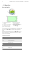
Installation on the measuring inset
A10066
1
2
3
4
Figure 11: Installation example
Note
Before mounting the transmitter on the measuring inset, remove
the ceramic block on the measuring inset and the captive screws
in the transmitter.
To install the transmitter on the measuring inset, cambered
toothed discs and the corresponding mounting screws are
required; these must be ordered as separate accessories:
Measuring inset installation set (2 fixing screws, 2 springs,
2 toothed discs) order number: 263750
1. Remove the ceramic block from the measuring inset
3.
2. Remove the screws from the transmitter
2. Remove the
sleeves from the screw holes and then remove the screws.
3. Insert new fixing screws
1 from above in the fixing holes of
the transmitter.
4. Place the cambered toothed discs
4 with curve facing
upward on the downward protruding screw thread.
5. Connect the power supply cable to the transmitter according
to connection diagram.
6. Place the transmitter in the housing on the measuring inset
and secure it.
Note
The toothed discs between measuring inset and transmitter are
straightened when the screws are tightened. This enables them
to grip the mounting screws.

TTH300 HEAD-MOUNT TEMPERATURE TRANSMITTER | OI/TTH300-EN REV. E 19
Installation in the cover of the connection head
1
2
3
A10067
Figure 12: Installation example
1. Release the screw plug
3 for the cover of the connection
head.
2. Open the cover
1.
3. Secure the transmitter
2 at the proper position on the
cover, using the captive screws found in the transmitter.
Installation on the top-hat rail
A10103
Figure 13: Installation example
When mounted on a top-hat rail, the transmitter can be placed at
a distance from the sensor in a housing that is suitable for the
ambient conditions.
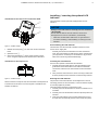
Installing / removing the optional LCD
indicator
The transmitter can be optionally equipped with an LCD
indicator.
NOTICE
Damage to the LCD indicator caused by incorrect installation
/ disassembly
The flat ribbon cable of the LCD indicator can become
damaged due to incorrect installation / disassembly.
• Make sure the flat ribbon cable does not get twisted or
torn when installing / disassembling or rotating the LCD
indicator.
Disassembling the LCD indicator
The indicator must be removed to enable connection of the
sensor line or supply line:
Carefully remove the LCD indicator from the transmitter
inset. The LCD indicator is held firmly in place, meaning that
you may have to use the tip of a screwdriver to pry it loose.
Take care to avoid any mechanical damage.
Installing the LCD indicator
No tools are required to install the LCD indicator.
1. Carefully insert the guide pins for the LCD indicator in the
guide holes of the transmitter inset. Make sure the black
connection socket fits into the terminal on the transmitter
inset.
2. Then press the LCD indicator in as far as it will go. Make sure
that the guide pins and connection socket are fully inserted.
Rotating the LCD indicator
The position of the LCD indicator can be adjusted to suit the
mounting position of the transmitter, to ensure that the display
is as clearly legible as possible.
There are twelve positions at increments of 30°.
1. Carefully turn the LCD indicator to the left to release it from
its holder.
2. Carefully turn the LCD indicator until the required position is
reached.
3. Insert the LCD indicator into its holder again and turn it to
the right into the required position until it snaps into place.

20 TTH300 HEAD-MOUNT TEMPERATURE TRANSMITTER | OI/TTH300-EN REV. E
8 Electrical connections
Safety instructions
DANGER
Improper installation and commissioning of the device
carries a risk of explosion.
For use in potentially explosive atmospheres, observe the
information in Use in potentially explosive atmospheres in
accordance with ATEX and IECEx on page 6 and Use in
potentially explosive atmospheres in accordance with FM
and CSA on page 12!
Observe the following instructions:
• The electrical connection may only be established by
authorized specialist personnel and in accordance with
the connection diagrams.
• The relevant regulations must be observed during electric
installation.
• The electrical connection information in the instruction
must be observed; otherwise, the electric IP rating may
be adversely affected.
• Safe isolation of electric circuits which are dangerous if
touched is ensured only if the connected devices satisfy
the requirements of DIN EN 61140 (VDE 0140 Part 1)
(basic requirements for safe isolation).
• To ensure safe isolation, install connection leads separate
from electric circuits which are dangerous if touched, or
implement additional insulation measures.
• Connections must only be established in a dead-voltage
state!
• The transmitter has no switch-off elements. Therefore,
overcurrent protective devices, lightning protection, or
voltage disconnection options must be provided with the
installation.
• The power supply and signal are routed in the same
conductor and should be implemented as a SELV or PELV
circuit in accordance with the relevant standard
(standard version). For the explosion-proof design, the
guidelines in accordance with the Ex standard must be
adhered to.
• You need to check that the available power supply
corresponds to the information on the name plate.
Note
The signal cable wires must be provided with wire end sleeves.
The slotted screws of the connection terminals are tightened
with a size 1 screwdriver (3.5 or 4 mm).
Protection of the transmitter from damage
caused by highly energetic electric
interferences
The transmitter has no switch-off elements. Therefore,
overcurrent protective devices, lightning protection, or voltage
disconnection options must be provided at the plant.
For the shielding and grounding of the device and the
connection cable, observe Pin assignment on page 22.
NOTICE
Temperature transmitter damage!
Overvoltage, overcurrent and high-frequency interference
signals on the supply connection as well as sensor connection
side of the device can damage the temperature transmitter.
A Do not weld
B No high-frequency interference signals / switching operations of large
consumers
C No overvoltage due to lightning
Figure 14: Warning signs
Overcurrent and overvoltage can occur through for example
welding operations, switching operations of large electric
consumers, or lightning in the vicinity of the transmitter, sensor,
as well as connector cables.
Temperature transmitters are sensitive devices on the sensor
side as well. Long connector cables to the sensor can encourage
damaging interference. This can already happen if temperature
sensors are connected to the transmitter during installation, but
are not yet integrated into the system (no connection to the
supply isolator / DCS)!
Page is loading ...
Page is loading ...
Page is loading ...
Page is loading ...
Page is loading ...
Page is loading ...
Page is loading ...
Page is loading ...
Page is loading ...
Page is loading ...
Page is loading ...
Page is loading ...
Page is loading ...
Page is loading ...
Page is loading ...
Page is loading ...
Page is loading ...
Page is loading ...
Page is loading ...
Page is loading ...
Page is loading ...
Page is loading ...
Page is loading ...
Page is loading ...
Page is loading ...
Page is loading ...
Page is loading ...
Page is loading ...
Page is loading ...
Page is loading ...
Page is loading ...
Page is loading ...
Page is loading ...
Page is loading ...
Page is loading ...
Page is loading ...
Page is loading ...
Page is loading ...
Page is loading ...
Page is loading ...
Page is loading ...
Page is loading ...
Page is loading ...
Page is loading ...
-
 1
1
-
 2
2
-
 3
3
-
 4
4
-
 5
5
-
 6
6
-
 7
7
-
 8
8
-
 9
9
-
 10
10
-
 11
11
-
 12
12
-
 13
13
-
 14
14
-
 15
15
-
 16
16
-
 17
17
-
 18
18
-
 19
19
-
 20
20
-
 21
21
-
 22
22
-
 23
23
-
 24
24
-
 25
25
-
 26
26
-
 27
27
-
 28
28
-
 29
29
-
 30
30
-
 31
31
-
 32
32
-
 33
33
-
 34
34
-
 35
35
-
 36
36
-
 37
37
-
 38
38
-
 39
39
-
 40
40
-
 41
41
-
 42
42
-
 43
43
-
 44
44
-
 45
45
-
 46
46
-
 47
47
-
 48
48
-
 49
49
-
 50
50
-
 51
51
-
 52
52
-
 53
53
-
 54
54
-
 55
55
-
 56
56
-
 57
57
-
 58
58
-
 59
59
-
 60
60
-
 61
61
-
 62
62
-
 63
63
-
 64
64


ABB TTH300 Series Operating
- Category
- Measuring & layout tools
- Type
- Operating
- This manual is also suitable for
Ask a question and I''ll find the answer in the document
Finding information in a document is now easier with AI
Related papers
-
ABB TTF200 Operating
-
ABB 261GC Operating
-
-
-
-
-
-
-
-
Other documents
-
Renkforce E0001TA Owner's manual
-
GHM MU500L Owner's manual
-
IFM N0032A Operating instructions
-
Omega DP9602 Owner's manual
-
AMS USB Fieldbus Interface Rev 3 Owner's manual
-
SMAR TT301 User manual
-
IFM SP321A Operating instructions
-
Uncategorized B&K Precision DAS220-BAT/DAS240-BAT Portable Data Recorders User manual
-
-
WIKA T91.30 Operating instructions