
02/2017
130R0536 MG18H202
*MG18H202*
February 2017
BAS-SVP16B-EN
BAS-SVP16B-EN
Trane has a policy of continous product and product data improvement and reserves the right to
change design and specifications without notice.
www.trane.com
For more information, contact your local Trane
office or e-mail us at [email protected]
Literature Order Number BAS-SVP16B-EN
Date February 2017
Supersedes September 2013
TR150 and TR170
Programming Guide

Contents
1 Introduction
3
1.1 Purpose of the Manual
3
1.2 Document and Software Version
3
1.3 Safety Symbols
3
1.4 Safety Precautions
3
1.5 Additional Resources
4
1.6
Denitions
5
1.7 Electrical Overview
7
2 Programming
8
2.1 Introduction
8
2.2 Local Control Panel (LCP)
8
2.3 Menus
9
2.3.1 Status Menu 9
2.3.2 Quick Menu 9
2.3.3 Main Menu 23
2.4 Quick Transfer of Parameter Settings between Multiple Frequency Converters
23
2.5 Readout and Programming of Indexed Parameters
24
2.6 Initialization to Default Settings
24
3 Parameters
25
3.1 Main Menu - Operation and Display - Group 0
25
3.2 Main Menu - Load and Motor - Group 1
29
3.3 Main Menu - Brakes - Group 2
39
3.4 Main Menu–Reference/Ramps–Group 3
41
3.5 Main Menu - Limits/Warnings - Group 4
44
3.6 Main Menu - Digital In/Out - Group 5
47
3.7 Main Menu - Analog In/Out - Group 6
55
3.8 Main Menu - Communications and Options - Group 8
60
3.9 Main Menu - Smart Logic - Group 13
65
3.10 Main Menu - Special Functions - Group 14
73
3.11 Main Menu - Drive Information - Group 15
77
3.12 Main Menu - Data Readouts - Group 16
79
3.13 Main Menu - Data Readouts 2 - Group 18
83
3.14 Main Menu - FC Closed Loop - Group 20
84
3.15 Main Menu - Application Functions - Group 22
86
3.16 Main Menu - Application Functions 2 - Group 24
92
3.17 Main Menu - Special Features - Group 30
95
4 Troubleshooting
96
Contents Programming Guide
BAS-SVP16B-EN 02/2017 All rights reserved. 1

4.1 Introduction to Alarms and Warnings
96
4.2 Alarm Words
98
4.3 Warning Words
98
4.4 Extended Status Words
99
4.5 List of Warnings and Alarms
99
4.6 List of LCP Errors
102
5 Parameter Lists
103
5.1 Parameter Options
103
5.1.1 Default Settings 103
5.1.2 0-** Operation/Display 104
5.1.3 1-** Load and Motor 104
5.1.4 2-** Brakes 106
5.1.5 3-** Reference/Ramps 106
5.1.6 4-** Limits/Warnings 107
5.1.7 5-** Digital In/Out 107
5.1.8 6-** Analog In/Out 108
5.1.9 8-** Comm. and Options 109
5.1.10 13-** Smart Logic 110
5.1.11 14-** Special Functions 110
5.1.12 15-** Drive Information 111
5.1.13 16-** Data Readouts 112
5.1.14 18-** Info & Readouts 113
5.1.15 20-** Drive Closed Loop 113
5.1.16 22-** Appl. Functions 114
5.1.17 24-** Appl. Functions 2 115
5.1.18 30-** Special Features 115
Index
116
Contents TR150 and TR170
2 02/2017 All rights reserved. BAS-SVP16B-EN

1Introduction
1.1 Purpose of the Manual
This programming guide provides information for
advanced programming of the frequency converter. It
provides a complete overview of all parameters and
descriptions for all parameters.
The programming guide is intended for use by qualied
personnel.
To operate the frequency converter safely and profes-
sionally, read and follow the programming guide, and pay
particular attention to the safety instructions and general
warnings.
1.2 Document and Software Version
This manual is regularly reviewed and updated. All
suggestions for improvement are welcome.
Edition Remarks Software version
BAS-SVP16B-EN Update to new
software version and
addition of TR170.
2.9x
Table 1.1 Document and Software Version
1.3 Safety Symbols
The following symbols are used in this guide:
WARNING
Indicates a potentially hazardous situation that could
result in death or serious injury.
CAUTION
Indicates a potentially hazardous situation that could
result in minor or moderate injury. It can also be used to
alert against unsafe practices.
NOTICE
Indicates important information, including situations that
can result in damage to equipment or property.
1.4 Safety Precautions
WARNING
HIGH VOLTAGE
Frequency converters contain high voltage when
connected to AC mains input, DC supply, or load sharing.
Failure to perform installation, start-up, and maintenance
by qualied personnel can result in death or serious
injury.
•
Only qualied personnel must perform instal-
lation, start-up, and maintenance.
WARNING
UNINTENDED START
When the frequency converter is connected to AC mains,
DC supply, or load sharing, the motor can start at any
time. Unintended start during programming, service, or
repair work can result in death, serious injury, or
property damage. The motor can start with an external
switch, a
eldbus
command, an input reference signal
from the LCP or LOP, via remote operation using Trane
Drive Utility (TDU), or after a cleared fault condition.
To prevent unintended motor start:
•
Press
[O/Reset]
on the LCP before
programming parameters.
•
Disconnect the frequency converter from the
mains.
•
Completely wire and assemble the frequency
converter, motor, and any driven equipment
before connecting the frequency converter to
AC mains, DC supply, or load sharing.
Introduction Programming Guide
BAS-SVP16B-EN 02/2017 All rights reserved. 3
1 1

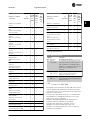
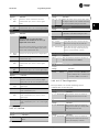
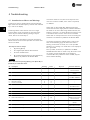
WARNING
DISCHARGE TIME
The frequency converter contains DC-link capacitors,
which can remain charged even when the frequency
converter is not powered. High voltage can be present
even when the warning LED indicator lights are o.
Failure to wait the specied time after power has been
removed before performing service or repair work can
result in death or serious injury.
•
Stop the motor.
•
Disconnect AC mains and remote DC-link power
supplies, including battery back-ups, UPS, and
DC-link connections to other frequency
converters.
•
Disconnect or lock PM motor.
•
Wait for the capacitors to discharge fully. The
minimum duration of waiting time is
specied
in Table 1.2.
•
Before performing any service or repair work,
use an appropriate voltage measuring device to
make sure that the capacitors are fully
discharged.
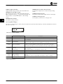
Voltage [V] Power range [kW (hp)] Minimum waiting time
(minutes)
3x200 0.25–3.7 (0.33–5) 4
3x200 5.5–11 (7–15) 15
3x400 0.37–7.5 (0.5–10) 4
3x400 11–90 (15–125) 15
3x600 2.2–7.5 (3–10) 4
3x600 11–90 (15–125) 15
Table 1.2 Discharge Time
WARNING
LEAKAGE CURRENT HAZARD
Leakage currents exceed 3.5 mA. Failure to ground the
frequency converter properly can result in death or
serious injury.
•
Ensure the correct grounding of the equipment
by a certied electrical installer.
WARNING
EQUIPMENT HAZARD
Contact with rotating shafts and electrical equipment
can result in death or serious injury.
•
Ensure that only trained and qualied personnel
perform installation, start-up, and maintenance.
•
Ensure that electrical work conforms to national
and local electrical codes.
•
Follow the procedures in this manual.
CAUTION
INTERNAL FAILURE HAZARD
An internal failure in the frequency converter can result
in serious injury when the frequency converter is not
properly closed.
•
Ensure that all safety covers are in place and
securely fastened before applying power.
1.5 Additional Resources
•
TR150 and TR170 Quick Guide provides basic
information on mechanical dimensions, instal-
lation, and programming
•
TR150 and TR170 Design Guide provides
information on how to design motor control
systems.
•
The Trane Drive Energy Analysis Program is
available at www.TraneDrives.com
The software allows energy consumption
comparisons of HVAC fans and pumps driven by
Trane frequency converters and alternative
methods of ow control. Use this tool to project
the costs, savings, and payback of using Trane
frequency converters on HVAC fans, pumps, and
cooling towers.
Trane technical literature is available in electronic form on
the documentation CD that is shipped with the product, or
in print from your local Trane sales
oce.
It is also available online at: www.trane.com/vfd.
Trane Drive Utility (TDU) support
Download the software from www.trane.com/vfd.
During the installation process of the software, enter CD
key 52314600. A license key is not required for basic
operation. For advanced features enter license key
11131111.
The latest software does not always contain the latest
updates for frequency converters. Contact the local sales
oce for the latest frequency converter updates (in the
form of *.upd les), or download the frequency converter
updates from www.tranedrives.com.
Introduction TR150 and TR170
4 02/2017 All rights reserved. BAS-SVP16B-EN
1
1

1.6
Denitions
Frequency converter
I
DRIVE, MAX
The maximum output current.
I
DRIVE, N
The rated output current supplied by the frequency
converter.
U
DRIVE, MAX
The maximum output voltage.
Input
The connected motor can start and stop via LCP and
digital inputs. Functions are divided into 2 groups, as
described in Table 1.3. Functions in group 1 have higher
priority than functions in group 2.
Group 1
Reset, coast stop, reset and coast stop, quick
stop, DC brake, stop, and
[O].
Group 2
Start, pulse start, reversing, start reversing, jog,
and freeze output.
Table 1.3 Control Commands
Motor
f
JOG
The motor frequency when the jog function is activated
(via digital terminals).
f
M
The motor frequency.
f
MAX
The maximum motor frequency.
f
MIN
The minimum motor frequency.
f
M,N
The rated motor frequency (nameplate data).
I
M
The motor current.
I
M,N
The rated motor current (nameplate data).
n
M,N
The nominal motor speed (nameplate data).
P
M,N
The rated motor power (nameplate data).
U
M
The instantaneous motor voltage.
U
M,N
The rated motor voltage (nameplate data).
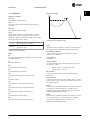
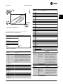
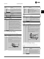
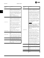
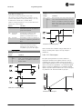
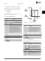
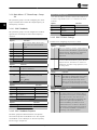
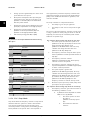
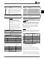
Break-away torque
Illustration 1.1 Break-away Torque
η
DRIVE
The eciency of the frequency converter is dened as the
ratio between the power output and the power input.
Start-disable command
A stop command belonging to the group 1 control
commands, see Table 1.3.
Stop command
See Table 1.3.
Analog reference
A signal transmitted to the analog inputs 53 or 54. It can
be voltage or current.
•
Current input: 0–20 mA and 4–20 mA
•
Voltage input: 0–10 V DC
Bus reference
A signal transmitted to the serial communication port
(drive port).
Preset reference
A dened preset reference to be set from -100% to +100%
of the reference range. Selection of 8 preset references via
the digital terminals.
Ref
MAX
Determines the relationship between the reference input at
100% full scale value (typically 10 V, 20 mA) and the
resulting reference. The maximum reference value set in
parameter 3-03 Maximum Reference.
Ref
MIN
Determines the relationship between the reference input at
0% value (typically 0 V, 0 mA, 4 mA) and the resulting
reference. The minimum reference value is set in
parameter 3-02 Minimum Reference.
Introduction Programming Guide
BAS-SVP16B-EN 02/2017 All rights reserved. 5
1 1

Analog inputs
The analog inputs are used for controlling various
functions of the frequency converter.
There are 2 types of analog inputs:
•
Current input: 0–20 mA and 4–20 mA
•
Voltage input: 0–10 V DC
Analog outputs
The analog outputs can supply a signal of 0–20 mA, 4–
20 mA, or a digital signal.
Automatic motor adaptation, AMA
The AMA algorithm determines the electrical parameters
for the connected motor at standstill and compensates for
the resistance based on the length of the motor cable.
Digital inputs
The digital inputs can be used for controlling various
functions of the frequency converter.
Digital outputs
The frequency converter provides 2 solid-state outputs that
can supply a 24 V DC (maximum 40 mA) signal.
Relay outputs
The frequency converter provides 2 programmable relay
outputs.
ETR
Electronic thermal relay is a thermal load calculation based
on present load and time. Its purpose is to estimate the
motor temperature and prevent overheating of the motor.
Initializing
If initializing is carried out (parameter 14-22 Operation
Mode), the programmable parameters of the frequency
converter return to their default settings.
Parameter 14-22 Operation Mode does not initialize
communication parameters, fault log, or re mode log.
Intermittent duty cycle
An intermittent duty rating refers to a sequence of duty
cycles. Each cycle consists of an on-load and an o-load
period. The operation can be either periodic duty or none-
periodic duty.
Keypad
The keypad makes up a complete interface for control and
programming of the frequency converter. The keypad is
detachable on IP20 units and
xed
on IP54 units. It can be
installed up to 3 m (9.8 ft) from the frequency converter,
that is, in a front panel with the installation kit option.
Lsb
Least signicant bit.
MCM
Short for mille circular mil, an American measuring unit for
cable cross-section. 1 MCM = 0.5067 mm
2
.
Msb
Most signicant bit.
On-line/O-line parameters
Changes to on-line parameters are activated immediately
after the data value is changed. Press [OK] to activate o-
line parameters.
PI controller
The PI controller maintains the desired speed, pressure,
temperature, and so on, by adjusting the output frequency
to match the varying load.
RCD
Residual current device.
Set-up
Parameter settings in 2 set-ups can be saved. Change
between the 2 parameter set-ups and edit 1 set-up, while
another set-up is active.
Slip compensation
The frequency converter compensates for the motor slip by
giving the frequency a supplement that follows the
measured motor load keeping the motor speed almost
constant.
Smart logic control (SLC)
The SLC is a sequence of user-dened actions executed
when the associated user-dened events are evaluated as
true by the SLC.
Thermistor
A temperature-dependent resistor placed where the
temperature is to be monitored (frequency converter or
motor).
Trip
A state entered in fault situations, for example, if the
frequency converter is subject to an overtemperature or
when the frequency converter is protecting the motor,
process, or mechanism. Restart is prevented until the cause
of the fault does not exist and the trip state is canceled by
activating reset or, sometimes, by being programmed to
reset automatically. Do not use trip for personal safety.
Trip lock
A state entered in fault situations when the frequency
converter is protecting itself and requiring physical
intervention, for example, if the frequency converter is
subject to a short circuit on the output. A locked trip can
only be canceled by cutting o mains, removing the cause
of the fault, and reconnecting the frequency converter.
Restart is prevented until the trip state is canceled by
activating reset or, sometimes, by being programmed to
reset automatically. Do not use trip lock for personal safety.
VT characteristics
Variable torque characteristics used for pumps and fans.
VVC
+
If compared with standard voltage/frequency ratio control,
voltage vector control (VVC
+
) improves the dynamics and
the stability, both when the speed reference is changed
and in relation to the load torque.
Introduction TR150 and TR170
6 02/2017 All rights reserved. BAS-SVP16B-EN
1
1

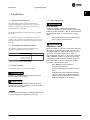
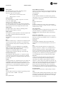
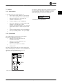
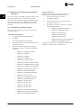
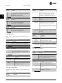
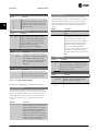
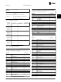
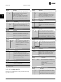
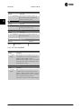
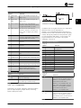
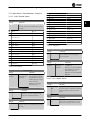
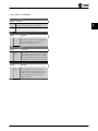
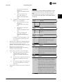
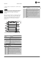
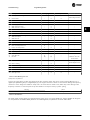
1.7 Electrical Overview
Illustration 1.2 Basic Wiring Schematic Drawing
NOTICE
There is no access to UDC- and UDC+ on the following units:
•
IP20, 380–480 V, 30–90 kW (40–125 hp)
•
IP20, 200–240 V, 15–45 kW (20–60 hp)
•
IP20, 525–600 V, 2.2–90 kW (3–125 hp)
•
IP54, 380–480 V, 22–90 kW (30–125 hp)
Introduction Programming Guide
BAS-SVP16B-EN 02/2017 All rights reserved. 7
1 1

2Programming
2.1 Introduction
The frequency converter can be programmed from the LCP
or from a PC via the RS485 COM port by installing the
Trane Drive Utility (TDU). Refer to chapter 1.5 Additional
Resources for more details about the software.
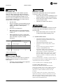
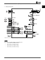
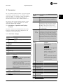
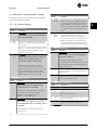
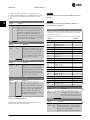
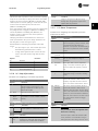
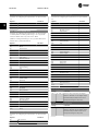
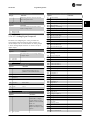
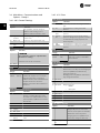
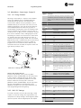
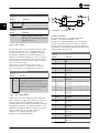
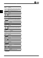
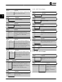
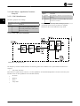
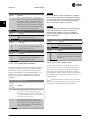
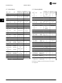
2.2 Local Control Panel (LCP)
The keypad is divided into 4 functional sections.
A. Display
B. Menu key
C. Navigation keys and indicator lights
D. Operation keys and indicator lights
Illustration 2.1 Keypad
A. Display
The LCD-display is illuminated with 2 alphanumeric lines.
All data is displayed on the keypad.
Illustration 2.1 describes the information that can be read
from the display.
1 Parameter number and name.
2 Parameter value.
3
Set-up number shows the active set-up and the edit set-up.
If the same set-up acts as both active and edit set-up, only
that set-up number is shown (factory setting). When active
and edit set-up dier, both numbers are shown in the
display (set-up 12). The number
ashing,
indicates the edit
set-up.
4
Motor direction is shown to the bottom left of the display –
indicated by a small arrow pointing either clockwise or
counterclockwise.
5
The triangle indicates if the keypad is in Status, Quick
Menu, or Main Menu.
Table 2.1 Legend to Illustration 2.1, Part I
B. Menu key
Press [Menu] to select among Status, Quick Menu, or Main
Menu.
C. Navigation keys and indicator lights
6 Com. LED: Flashes during bus communication.
7 Green LED/On: Control section is working correctly.
8 Yellow LED/Warn.: Indicates a warning.
9 Flashing Red LED/Alarm: Indicates an alarm.
10
[Back]: For moving to the previous step or layer in the
navigation structure.
11
[
▲
] [
▼
] [
►
]: For navigating among parameter groups and
parameters, and within parameters. They can also be used
for setting local reference.
12
[OK]: For selecting a parameter and for accepting changes
to parameter settings.
Table 2.2 Legend to Illustration 2.1, Part II
D. Operation keys and indicator lights
13
[Hand On]: Starts the motor and enables control of the
frequency converter via the keypad.
NOTICE
[2] Coast inverse is the default option for
parameter 5-12 Terminal 27 Digital Input. If there is
no 24 V supply to terminal 27, [Hand On] does not
start the motor. Connect terminal 12 to terminal 27.
14
[O/Reset]: Stops the motor (O). If in alarm mode, the
alarm is reset.
15
[Auto On]: The frequency converter is controlled either via
control terminals or serial communication.
Table 2.3 Legend to Illustration 2.1, Part III
Programming TR150 and TR170
8 02/2017 All rights reserved. BAS-SVP16B-EN
2
2

2.3 Menus
2.3.1 Status Menu
In the Status menu, the selection options are:
•
Motor frequency [Hz], parameter 16-13 Frequency.
•
Motor current [A], parameter 16-14 Motor current.
•
Motor speed reference in percentage [%],
parameter 16-02 Reference [%].
•
Feedback, parameter 16-52 Feedback[Unit].
•
Motor power parameter 16-10 Power [kW] for kW,
parameter 16-11 Power [hp] for hp. If
parameter 0-03 Regional Settings is set to [1] North
America, motor power is shown in hp instead of
kW.
•
Custom readout parameter 16-09 Custom Readout.
•
Motor Speed [RPM] parameter 16-17 Speed [RPM].
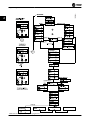
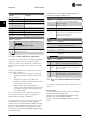
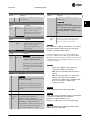
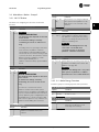
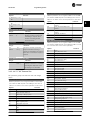
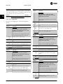
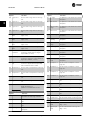
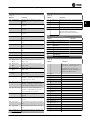
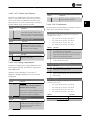
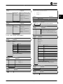
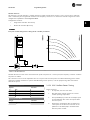
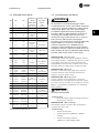
2.3.2 Quick Menu
Use the Quick Menu to program the most common
functions. The Quick Menu consists of:
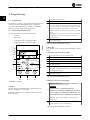
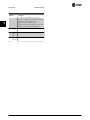
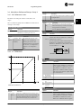
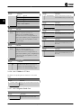
•
Wizard for open-loop applications. See
Illustration 2.4 for details.
•
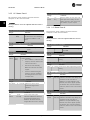
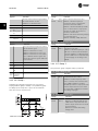
Wizard for closed-loop applications. See
Illustration 2.5 for details.
•
Motor set-up. See Table 2.6 for details.
•
Changes made.
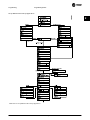
The built-in wizard menu guides the installer through the
set-up of the frequency converter in a clear and structured
manner for open-loop applications, closed-loop
applications, and quick motor settings.
Illustration 2.2 Frequency Converter Wiring
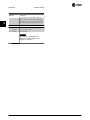
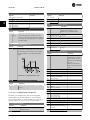
The wizard is displayed after power-up until any parameter
has been changed. The wizard can always be accessed
again through the quick menu. Press [OK] to start the
wizard. Press [Back] to return to the status view.
Illustration 2.3 Start-up/Quit Wizard
Programming Programming Guide
BAS-SVP16B-EN 02/2017 All rights reserved. 9
2
2

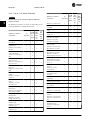
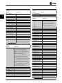
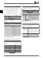
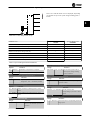
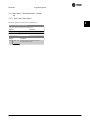
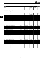
Illustration 2.4 Set-up Wizard for Open-loop Applications
Programming TR150 and TR170
10 02/2017 All rights reserved. BAS-SVP16B-EN
2
2

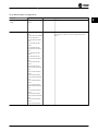
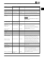
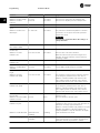
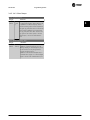
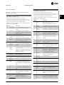
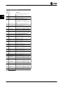
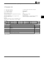
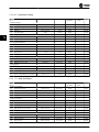
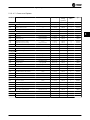
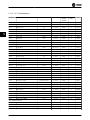
Set-up Wizard for Open-loop Applications
Parameter Option Default Usage
Parameter 0-03 Regional
Settings
[0] International
[1] US
[0] International –
Parameter 0-06 GridType [0] 200–240 V/50 Hz/IT-
grid
[1] 200–240 V/50 Hz/Delta
[2] 200–240 V/50 Hz
[10] 380–440 V/50 Hz/IT-
grid
[11] 380–440 V/50 Hz/
Delta
[12] 380–440 V/50 Hz
[20] 440–480 V/50 Hz/IT-
grid
[21] 440–480 V/50 Hz/
Delta
[22] 440–480 V/50 Hz
[30] 525–600 V/50 Hz/IT-
grid
[31] 525–600 V/50 Hz/
Delta
[32] 525–600 V/50 Hz
[100] 200–240 V/60 Hz/IT-
grid
[101] 200–240 V/60 Hz/
Delta
[102] 200–240 V/60 Hz
[110] 380–440 V/60 Hz/IT-
grid
[111] 380–440 V/60 Hz/
Delta
[112] 380–440 V/60 Hz
[120] 440–480 V/60 Hz/IT-
grid
[121] 440–480 V/60 Hz/
Delta
[122] 440–480 V/60 Hz
[130] 525–600 V/60 Hz/IT-
grid
[131] 525–600 V/60 Hz/
Delta
[132] 525–600 V/60 Hz
Size related Select the operating mode for restart after reconnection of
the frequency converter to mains voltage after power-
down.
Programming Programming Guide
BAS-SVP16B-EN 02/2017 All rights reserved. 11
2
2

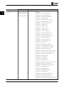
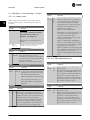
Parameter Option Default Usage
Parameter 1-10 Motor
Construction
*[0] Asynchron
[1] PM, non-salient SPM
[2] PM, salient IPM, non
Sat.
[3] PM, salient IPM, Sat.
[0] Asynchron Setting the parameter value might change these
parameters:
•
Parameter 1-01 Motor Control Principle.
•
Parameter 1-03 Torque Characteristics.
•
Parameter 1-08 Motor Control Bandwidth.
•
Parameter 1-14 Damping Gain.
•
Parameter 1-15 Low Speed Filter Time Const.
•
Parameter 1-16 High Speed Filter Time Const.
•
Parameter 1-17 Voltage
lter
time const.
•
Parameter 1-20 Motor Power.
•
Parameter 1-22 Motor Voltage.
•
Parameter 1-23 Motor Frequency.
•
Parameter 1-24 Motor Current.
•
Parameter 1-25 Motor Nominal Speed.
•
Parameter 1-26 Motor Cont. Rated Torque.
•
Parameter 1-30 Stator Resistance (Rs).
•
Parameter 1-33 Stator Leakage Reactance (X1).
•
Parameter 1-35 Main Reactance (Xh).
•
Parameter 1-37 d-axis Inductance (Ld).
•
Parameter 1-38 q-axis Inductance (Lq).
•
Parameter 1-39 Motor Poles.
•
Parameter 1-40 Back EMF at 1000 RPM.
•
Parameter 1-44 d-axis Inductance Sat. (LdSat).
•
Parameter 1-45 q-axis Inductance Sat. (LqSat).
•
Parameter 1-46 Position Detection Gain.
•
Parameter 1-48 Current at Min Inductance for d-axis.
•
Parameter 1-49 Current at Min Inductance for q-axis.
•
Parameter 1-66 Min. Current at Low Speed.
•
Parameter 1-70 PM Start Mode.
•
Parameter 1-72 Start Function.
•
Parameter 1-73 Flying Start.
•
Parameter 1-80 Function at Stop.
•
Parameter 1-82 Min Speed for Function at Stop [Hz].
•
Parameter 1-90 Motor Thermal Protection.
•
Parameter 2-00 DC Hold/Motor Preheat Current.
•
Parameter 2-01 DC Brake Current.
•
Parameter 2-02 DC Braking Time.
•
Parameter 2-04 DC Brake Cut In Speed.
•
Parameter 2-10 Brake Function.
•
Parameter 4-14 Motor Speed High Limit [Hz].
•
Parameter 4-19 Max Output Frequency.
•
Parameter 4-58 Missing Motor Phase Function.
•
Parameter 14-65 Speed Derate Dead Time Compensation.
Programming TR150 and TR170
12 02/2017 All rights reserved. BAS-SVP16B-EN
2
2

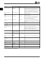
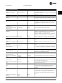
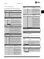
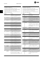
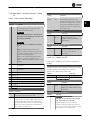
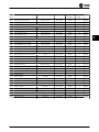
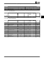
Parameter Option Default Usage
Parameter 1-20 Motor Power 0.12–110 kW/0.16–150
hp
Size related Enter the motor power from the nameplate data.
Parameter 1-22 Motor Voltage 50–1000 V Size related Enter the motor voltage from the nameplate data.
Parameter 1-23 Motor
Frequency
20–400 Hz Size related Enter the motor frequency from the nameplate data.
Parameter 1-24 Motor Current 0.01–10000.00 A Size related Enter the motor current from the nameplate data.
Parameter 1-25 Motor Nominal
Speed
50–9999 RPM Size related Enter the motor nominal speed from the nameplate data.
Parameter 1-26 Motor Cont.
Rated Torque
0.1–1000.0 Nm Size related This parameter is available when parameter 1-10 Motor
Construction is set to options that enable permanent
magnet motor mode.
NOTICE
Changing this parameter aects the settings of
other parameters.
Parameter 1-29 Automatic
Motor Adaption (AMA)
See
parameter 1-29 Automatic
Motor Adaption (AMA).
O Performing an AMA optimizes motor performance.
Parameter 1-30 Stator
Resistance (Rs)
0.000–99.990
Ω
Size related Set the stator resistance value.
Parameter 1-37 d-axis
Inductance (Ld)
0.000–1000.000 mH Size related Enter the value of the d-axis inductance.
Obtain the value from the permanent magnet motor
datasheet. The d-axis inductance cannot be found by
performing an AMA.
Parameter 1-38 q-axis
Inductance (Lq)
0.000–1000.000 mH Size related Enter the value of the q-axis inductance.
Parameter 1-39 Motor Poles 2–100 4 Enter the number of motor poles.
Parameter 1-40 Back EMF at
1000 RPM
10–9000 V Size related Line-line RMS back EMF voltage at 1000 RPM.
Parameter 1-42 Motor Cable
Length
0–100 m 50 m Enter the motor cable length.
Parameter 1-44 d-axis
Inductance Sat. (LdSat)
0.000–1000.000 mH Size related This parameter corresponds to the inductance saturation
of Ld. Ideally, this parameter has the same value as
parameter 1-37 d-axis Inductance (Ld). However, if the
motor supplier provides an induction curve, enter the
induction value, which is 200% of the nominal current.
Parameter 1-45 q-axis
Inductance Sat. (LqSat)
0.000–1000.000 mH Size related This parameter corresponds to the inductance saturation
of Lq. Ideally, this parameter has the same value as
parameter 1-38 q-axis Inductance (Lq). However, if the
motor supplier provides an induction curve, enter the
induction value, which is 200% of the nominal current.
Parameter 1-46 Position
Detection Gain
20–200% 100% Adjusts the height of the test pulse during position
detection at start.
Parameter 1-48 Current at Min
Inductance for d-axis
20–200% 100% Enter the inductance saturation point.
Parameter 1-49 Current at Min
Inductance for q-axis
20–200% 100% This parameter species the saturation curve of the d- and
q-inductance values. From 20–100% of this parameter, the
inductances are linearly approximated due to
parameter 1-37 d-axis Inductance (Ld), parameter 1-38 q-axis
Inductance (Lq), parameter 1-44 d-axis Inductance Sat.
(LdSat), and parameter 1-45 q-axis Inductance Sat. (LqSat).
Parameter 1-70 PM Start Mode [0] Rotor Detection
[1] Parking
[1] Parking Select the PM motor start mode.
Programming Programming Guide
BAS-SVP16B-EN 02/2017 All rights reserved. 13
2
2

Parameter Option Default Usage
Parameter 1-73 Flying Start [0] Disabled
[1] Enabled
[0] Disabled Select [1] Enabled to enable the frequency converter to
catch a motor spinning due to mains drop-out. Select [0]
Disabled if this function is not required. When this
parameter is set to [1] Enabled, parameter 1-71 Start Delay
and parameter 1-72 Start Function are not functional.
Parameter 1-73 Flying Start is active in VVC
+
mode only.
Parameter 3-02 Minimum
Reference
-4999.000–4999.000 0 The minimum reference is the lowest value obtainable by
summing all references.
Parameter 3-03 Maximum
Reference
-4999.000–4999.000 50 The maximum reference is the lowest obtainable by
summing all references.
Parameter 3-41 Ramp 1 Ramp
Up Time
0.05–3600.00 s Size related If asynchronous motor is selected, the ramp-up time is
from 0 to rated parameter 1-23 Motor Frequency. If PM
motor is selected, the ramp-up time is from 0 to
parameter 1-25 Motor Nominal Speed.
Parameter 3-42 Ramp 1 Ramp
Down Time
0.05–3600.00 s Size related For asynchronous motors, the ramp-down time is from
rated parameter 1-23 Motor Frequency to 0. For PM motors,
the ramp-down time is from parameter 1-25 Motor Nominal
Speed to 0.
Parameter 4-12 Motor Speed
Low Limit [Hz]
0.0–400.0 Hz 0 Hz Enter the minimum limit for low speed.
Parameter 4-14 Motor Speed
High Limit [Hz]
0.0–400.0 Hz 100 Hz Enter the maximum limit for high speed.
Parameter 4-19 Max Output
Frequency
0.0–400.0 Hz 100 Hz Enter the maximum output frequency value. If
parameter 4-19 Max Output Frequency is set lower than
parameter 4-14 Motor Speed High Limit [Hz],
parameter 4-14 Motor Speed High Limit [Hz] is set equal to
parameter 4-19 Max Output Frequency automatically.
Parameter 5-40 Function Relay See
parameter 5-40 Function
Relay.
[9] Alarm Select the function to control output relay 1.
Parameter 5-40 Function Relay See
parameter 5-40 Function
Relay.
[5] Drive running Select the function to control output relay 2.
Parameter 6-10 Terminal 53 Low
Voltage
0.00–10.00 V 0.07 V Enter the voltage that corresponds to the low reference
value.
Parameter 6-11 Terminal 53
High Voltage
0.00–10.00 V 10 V Enter the voltage that corresponds to the high reference
value.
Parameter 6-12 Terminal 53 Low
Current
0.00–20.00 mA 4 mA Enter the current that corresponds to the low reference
value.
Parameter 6-13 Terminal 53
High Current
0.00–20.00 mA 20 mA Enter the current that corresponds to the high reference
value.
Parameter 6-19 Terminal 53
mode
[0] Current
[1] Voltage
[1] Voltage Select if terminal 53 is used for current or voltage input.
Parameter 30-22 Locked Rotor
Detection
[0] O
[1] On
[0] O
–
Parameter 30-23 Locked Rotor
Detection Time [s]
0.05–1 s 0.10 s
–
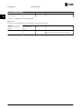
Table 2.4 Set-up Wizard for Open-loop Applications
Programming TR150 and TR170
14 02/2017 All rights reserved. BAS-SVP16B-EN
2
2

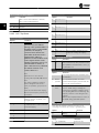
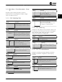
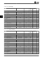
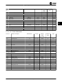
Set-up Wizard for Closed-loop Applications
Illustration 2.5 Set-up Wizard for Closed-loop Applications
Programming Programming Guide
BAS-SVP16B-EN 02/2017 All rights reserved. 15
2
2

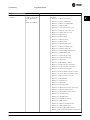
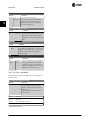
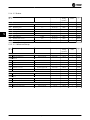
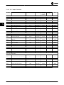
Parameter Range Default Usage
Parameter 0-03 Regional
Settings
[0] International
[1] US
[0] International –
Parameter 0-06 GridType [0]–[132] see Table 2.4. Size selected Select the operating mode for restart after reconnection of
the frequency converter to mains voltage after power-
down.
Parameter 1-00 Conguration
Mode
[0] Open loop
[3] Closed loop
[0] Open loop Select [3] Closed loop.
Programming TR150 and TR170
16 02/2017 All rights reserved. BAS-SVP16B-EN
2
2

Parameter Range Default Usage
Parameter 1-10 Motor
Construction
*[0] Asynchron
[1] PM, non-salient SPM
[2] PM, salient IPM, non
Sat.
[3] PM, salient IPM, Sat.
[0] Asynchron Setting the parameter value might change these
parameters:
•
Parameter 1-01 Motor Control Principle.
•
Parameter 1-03 Torque Characteristics.
•
Parameter 1-08 Motor Control Bandwidth.
•
Parameter 1-14 Damping Gain.
•
Parameter 1-15 Low Speed Filter Time Const.
•
Parameter 1-16 High Speed Filter Time Const.
•
Parameter 1-17 Voltage
lter
time const.
•
Parameter 1-20 Motor Power.
•
Parameter 1-22 Motor Voltage.
•
Parameter 1-23 Motor Frequency.
•
Parameter 1-24 Motor Current.
•
Parameter 1-25 Motor Nominal Speed.
•
Parameter 1-26 Motor Cont. Rated Torque.
•
Parameter 1-30 Stator Resistance (Rs).
•
Parameter 1-33 Stator Leakage Reactance (X1).
•
Parameter 1-35 Main Reactance (Xh).
•
Parameter 1-37 d-axis Inductance (Ld).
•
Parameter 1-38 q-axis Inductance (Lq).
•
Parameter 1-39 Motor Poles.
•
Parameter 1-40 Back EMF at 1000 RPM.
•
Parameter 1-44 d-axis Inductance Sat. (LdSat).
•
Parameter 1-45 q-axis Inductance Sat. (LqSat).
•
Parameter 1-46 Position Detection Gain.
•
Parameter 1-48 Current at Min Inductance for d-axis.
•
Parameter 1-49 Current at Min Inductance for q-axis.
•
Parameter 1-66 Min. Current at Low Speed.
•
Parameter 1-70 PM Start Mode.
•
Parameter 1-72 Start Function.
•
Parameter 1-73 Flying Start.
•
Parameter 1-80 Function at Stop.
•
Parameter 1-82 Min Speed for Function at Stop [Hz].
•
Parameter 1-90 Motor Thermal Protection.
•
Parameter 2-00 DC Hold/Motor Preheat Current.
•
Parameter 2-01 DC Brake Current.
•
Parameter 2-02 DC Braking Time.
•
Parameter 2-04 DC Brake Cut In Speed.
•
Parameter 2-10 Brake Function.
•
Parameter 4-14 Motor Speed High Limit [Hz].
•
Parameter 4-19 Max Output Frequency.
•
Parameter 4-58 Missing Motor Phase Function.
•
Parameter 14-65 Speed Derate Dead Time Compensation.
Programming Programming Guide
BAS-SVP16B-EN 02/2017 All rights reserved. 17
2
2

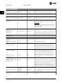
Parameter Range Default Usage
Parameter 1-20 Motor Power 0.09–110 kW Size related Enter the motor power from the nameplate data.
Parameter 1-22 Motor Voltage 50–1000 V Size related Enter the motor voltage from the nameplate data.
Parameter 1-23 Motor
Frequency
20–400 Hz Size related Enter the motor frequency from the nameplate data.
Parameter 1-24 Motor Current 0–10000 A Size related Enter the motor current from the nameplate data.
Parameter 1-25 Motor Nominal
Speed
50–9999 RPM Size related Enter the motor nominal speed from the nameplate data.
Parameter 1-26 Motor Cont.
Rated Torque
0.1–1000.0 Nm Size related This parameter is available when parameter 1-10 Motor
Construction is set to options that enable permanent
magnet motor mode.
NOTICE
Changing this parameter aects the settings of
other parameters.
Parameter 1-29 Automatic
Motor Adaption (AMA)
O Performing an AMA optimises motor performance.
Parameter 1-30 Stator
Resistance (Rs)
0–99.990 Ω Size related Set the stator resistance value.
Parameter 1-37 d-axis
Inductance (Ld)
0.000–1000.000 mH Size related Enter the value of the d-axis inductance.
Obtain the value from the permanent magnet motor
datasheet. The d-axis inductance cannot be found by
performing an AMA.
Parameter 1-38 q-axis
Inductance (Lq)
0.000–1000.000 mH Size related Enter the value of the q-axis inductance.
Parameter 1-39 Motor Poles 2–100 4 Enter the number of motor poles.
Parameter 1-40 Back EMF at
1000 RPM
10–9000 V Size related Line-line RMS back EMF voltage at 1000 RPM.
Parameter 1-42 Motor Cable
Length
0–100 m 50 m Enter the motor cable length.
Parameter 1-44 d-axis
Inductance Sat. (LdSat)
0.000–1000.000 mH Size related This parameter corresponds to the inductance saturation
of Ld. Ideally, this parameter has the same value as
parameter 1-37 d-axis Inductance (Ld). However, if the
motor supplier provides an induction curve, enter the
induction value, which is 200% of the nominal current.
Parameter 1-45 q-axis
Inductance Sat. (LqSat)
0.000–1000.000 mH Size related This parameter corresponds to the inductance saturation
of Lq. Ideally, this parameter has the same value as
parameter 1-38 q-axis Inductance (Lq). However, if the
motor supplier provides an induction curve, enter the
induction value, which is 200% of the nominal current.
Parameter 1-46 Position
Detection Gain
20–200% 100% Adjusts the height of the test pulse during position
detection at start.
Parameter 1-48 Current at Min
Inductance for d-axis
20–200% 100% Enter the inductance saturation point.
Parameter 1-49 Current at Min
Inductance for q-axis
20–200% 100% This parameter species the saturation curve of the d- and
q-inductance values. From 20–100% of this parameter, the
inductances are linearly approximated due to
parameter 1-37 d-axis Inductance (Ld), parameter 1-38 q-axis
Inductance (Lq), parameter 1-44 d-axis Inductance Sat.
(LdSat), and parameter 1-45 q-axis Inductance Sat. (LqSat).
Parameter 1-70 PM Start Mode [0] Rotor Detection
[1] Parking
[1] Parking Select the PM motor start mode.
Parameter 1-73 Flying Start [0] Disabled
[1] Enabled
[0] Disabled Select [1] Enabled to enable the frequency converter to
catch a spinning motor in, for example, fan applications.
When PM is selected, this parameter is enabled.
Programming TR150 and TR170
18 02/2017 All rights reserved. BAS-SVP16B-EN
2
2

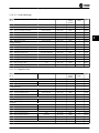
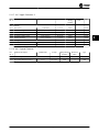
Parameter Range Default Usage
Parameter 3-02 Minimum
Reference
-4999.000–4999.000 0 The minimum reference is the lowest value obtainable by
summing all references.
Parameter 3-03 Maximum
Reference
-4999.000–4999.000 50 The maximum reference is the highest value obtainable by
summing all references.
Parameter 3-10 Preset Reference -100–100% 0 Enter the setpoint.
Parameter 3-41 Ramp 1 Ramp
Up Time
0.05–3600.0 s Size related Ramp-up time from 0 to rated parameter 1-23 Motor
Frequency for asynchronous motors. Ramp-up time from 0
to parameter 1-25 Motor Nominal Speed for PM motors.
Parameter 3-42 Ramp 1 Ramp
Down Time
0.05–3600.0 s Size related Ramp-down time from rated parameter 1-23 Motor
Frequency to 0 for asynchronous motors. Ramp-down time
from parameter 1-25 Motor Nominal Speed to 0 for PM
motors.
Parameter 4-12 Motor Speed
Low Limit [Hz]
0.0–400.0 Hz 0.0 Hz Enter the minimum limit for low speed.
Parameter 4-14 Motor Speed
High Limit [Hz]
0.0–400.0 Hz 100 Hz Enter the minimum limit for high speed.
Parameter 4-19 Max Output
Frequency
0.0–400.0 Hz 100 Hz Enter the maximum output frequency value. If
parameter 4-19 Max Output Frequency is set lower than
parameter 4-14 Motor Speed High Limit [Hz],
parameter 4-14 Motor Speed High Limit [Hz] is set equal to
parameter 4-19 Max Output Frequency automatically.
Parameter 6-20 Terminal 54 Low
Voltage
0.00–10.00 V 0.07 V Enter the voltage that corresponds to the low reference
value.
Parameter 6-21 Terminal 54
High Voltage
0.00–10.00 V 10.00 V Enter the voltage that corresponds to the high reference
value.
Parameter 6-22 Terminal 54 Low
Current
0.00–20.00 mA 4.00 mA Enter the current that corresponds to the low reference
value.
Parameter 6-23 Terminal 54
High Current
0.00–20.00 mA 20.00 mA Enter the current that corresponds to the high reference
value.
Parameter 6-24 Terminal 54 Low
Ref./Feedb. Value
-4999–4999 0 Enter the feedback value that corresponds to the voltage
or current set in parameter 6-20 Terminal 54 Low Voltage/
parameter 6-22 Terminal 54 Low Current.
Parameter 6-25 Terminal 54
High Ref./Feedb. Value
-4999–4999 50 Enter the feedback value that corresponds to the voltage
or current set in parameter 6-21 Terminal 54 High Voltage/
parameter 6-23 Terminal 54 High Current.
Parameter 6-26 Terminal 54
Filter Time Constant
0.00–10.00 s 0.01 Enter the lter time constant.
Parameter 6-29 Terminal 54
mode
[0] Current
[1] Voltage
[1] Voltage Select if terminal 54 is used for current or voltage input.
Parameter 20-81 PI Normal/
Inverse Control
[0] Normal
[1] Inverse
[0] Normal Select [0] Normal to set the process control to increase the
output speed when the process error is positive. Select [1]
Inverse to reduce the output speed.
Parameter 20-83 PI Start Speed
[Hz]
0–200 Hz 0 Hz Enter the motor speed to be attained as a start signal for
commencement of PI control.
Parameter 20-93 PI Proportional
Gain
0.00–10.00 0.01 Enter the process controller proportional gain. Quick
control is obtained at high amplication. However, if
amplication is too high, the process may become
unstable.
Parameter 20-94 PI Integral
Time
0.1–999.0 s 999.0 s Enter the process controller integral time. Obtain quick
control through a short integral time, though if the
integral time is too short, the process becomes unstable.
An excessively long integral time disables the integral
action.
Parameter 30-22 Locked Rotor
Detection
[0] O
[1] On
[0] O
–
Programming Programming Guide
BAS-SVP16B-EN 02/2017 All rights reserved. 19
2
2
Page is loading ...
Page is loading ...
Page is loading ...
Page is loading ...
Page is loading ...
Page is loading ...
Page is loading ...
Page is loading ...
Page is loading ...
Page is loading ...
Page is loading ...
Page is loading ...
Page is loading ...
Page is loading ...
Page is loading ...
Page is loading ...
Page is loading ...
Page is loading ...
Page is loading ...
Page is loading ...
Page is loading ...
Page is loading ...
Page is loading ...
Page is loading ...
Page is loading ...
Page is loading ...
Page is loading ...
Page is loading ...
Page is loading ...
Page is loading ...
Page is loading ...
Page is loading ...
Page is loading ...
Page is loading ...
Page is loading ...
Page is loading ...
Page is loading ...
Page is loading ...
Page is loading ...
Page is loading ...
Page is loading ...
Page is loading ...
Page is loading ...
Page is loading ...
Page is loading ...
Page is loading ...
Page is loading ...
Page is loading ...
Page is loading ...
Page is loading ...
Page is loading ...
Page is loading ...
Page is loading ...
Page is loading ...
Page is loading ...
Page is loading ...
Page is loading ...
Page is loading ...
Page is loading ...
Page is loading ...
Page is loading ...
Page is loading ...
Page is loading ...
Page is loading ...
Page is loading ...
Page is loading ...
Page is loading ...
Page is loading ...
Page is loading ...
Page is loading ...
Page is loading ...
Page is loading ...
Page is loading ...
Page is loading ...
Page is loading ...
Page is loading ...
Page is loading ...
Page is loading ...
Page is loading ...
Page is loading ...
Page is loading ...
Page is loading ...
Page is loading ...
Page is loading ...
Page is loading ...
Page is loading ...
Page is loading ...
Page is loading ...
Page is loading ...
Page is loading ...
Page is loading ...
Page is loading ...
Page is loading ...
Page is loading ...
Page is loading ...
Page is loading ...
Page is loading ...
Page is loading ...
Page is loading ...
Page is loading ...
Page is loading ...
-
 1
1
-
 2
2
-
 3
3
-
 4
4
-
 5
5
-
 6
6
-
 7
7
-
 8
8
-
 9
9
-
 10
10
-
 11
11
-
 12
12
-
 13
13
-
 14
14
-
 15
15
-
 16
16
-
 17
17
-
 18
18
-
 19
19
-
 20
20
-
 21
21
-
 22
22
-
 23
23
-
 24
24
-
 25
25
-
 26
26
-
 27
27
-
 28
28
-
 29
29
-
 30
30
-
 31
31
-
 32
32
-
 33
33
-
 34
34
-
 35
35
-
 36
36
-
 37
37
-
 38
38
-
 39
39
-
 40
40
-
 41
41
-
 42
42
-
 43
43
-
 44
44
-
 45
45
-
 46
46
-
 47
47
-
 48
48
-
 49
49
-
 50
50
-
 51
51
-
 52
52
-
 53
53
-
 54
54
-
 55
55
-
 56
56
-
 57
57
-
 58
58
-
 59
59
-
 60
60
-
 61
61
-
 62
62
-
 63
63
-
 64
64
-
 65
65
-
 66
66
-
 67
67
-
 68
68
-
 69
69
-
 70
70
-
 71
71
-
 72
72
-
 73
73
-
 74
74
-
 75
75
-
 76
76
-
 77
77
-
 78
78
-
 79
79
-
 80
80
-
 81
81
-
 82
82
-
 83
83
-
 84
84
-
 85
85
-
 86
86
-
 87
87
-
 88
88
-
 89
89
-
 90
90
-
 91
91
-
 92
92
-
 93
93
-
 94
94
-
 95
95
-
 96
96
-
 97
97
-
 98
98
-
 99
99
-
 100
100
-
 101
101
-
 102
102
-
 103
103
-
 104
104
-
 105
105
-
 106
106
-
 107
107
-
 108
108
-
 109
109
-
 110
110
-
 111
111
-
 112
112
-
 113
113
-
 114
114
-
 115
115
-
 116
116
-
 117
117
-
 118
118
-
 119
119
-
 120
120
-
 121
121


Trane TR150 Programming Manual
- Type
- Programming Manual
- This manual is also suitable for
Ask a question and I''ll find the answer in the document
Finding information in a document is now easier with AI
Related papers
Other documents
-
Danfoss VLT HVAC Basic Drive FC 101 Operating instructions
-
-
-
-
-
-
Danfoss FC101-7,5k User guide
-
-
-
Danfoss VLT® HVAC Basic Drive FC 101 SW2.8x User guide