
Rev. 2009-06-18130R0451 MG12L122
*MG12L122*
BACnet
®
Option Module
Instruction Manual
November 2009
TR200
BAS-SVX24B-EN
Trane has a policy of continous product and product data improvement and reserves the right to
change design and specifications without notice.
www.trane.com
For more information, contact your local Trane
office or e-mail us at [email protected]
Literature Order Number BAS-SVX24A-EN
Date June 2009
Supersedes

Table of Contents
Safety
1-1
Copyright, limitation of liability and revision rights
1-1
High Voltage Warning
1-3
Before Commencing Repair Work
1-8
Special Conditions
1-8
Introduction
2-1
Introduction
2-1
How to Install
3-1
The BACnet Option
3-1
System Specifications
3-5
How to Configure the System
4-1
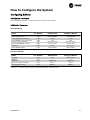
Configuring BACnet
4-1
BIBBs
4-2
Example of a simple set-up of BACnet
4-3
How to Control the Adjustable Frequency Drive
5-1
Network Adjustable Frequency Drive Control Inputs and Out-
puts
5-2
Adjustable Frequency Drive Feedback to Network
5-15
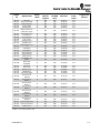
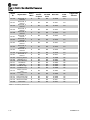
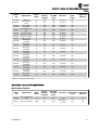
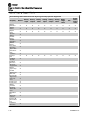
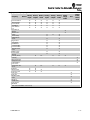
Parameters
6-1
Parameter Overview
6-1
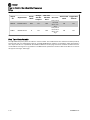
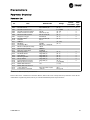
Parameter Description
6-2
Troubleshooting
7-1
Alarm, Warning and Extended Status Word
7-1
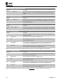
Alarm Words
7-2
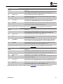
Warning Words
7-3
TR200 BACnet -1

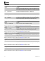
LED Status
7-4
-2 TR200 BACnet

Safety
Copyright, limitation of liability and revision rights
This publication contains information proprietary to Trane. By accepting and using this manual, the user agrees
that the information contained herein will be used solely for operating equipment from Trane or equipment
from other vendors provided that such equipment is intended for communication with Trane equipment over
a serial communication link. This publication is protected under the copyright laws of most countries.
Trane does not warrant that a software program produced according to the guidelines provided in this manual
will function properly in every physical, hardware or software environment.
Although Trane has tested and reviewed the documentation within this manual, Trane makes no warranty or
representation, neither expressed nor implied, with respect to this documentation, including its quality, per-
formance, or fitness for a particular purpose.
In no event shall Trane be liable for direct, indirect, special, incidental, or consequential damages arising out of
the use, or the inability to use information contained in this manual, even if advised of the possibility of such
damages. In particular, Trane is not responsible for any costs, including but not limited to those incurred as a
result of lost profits or revenue, loss or damage of equipment, loss of computer programs, loss of data, the costs
to substitute these, or any claims by third parties.
Trane reserves the right to revise this publication at any time and to make changes to its contents without prior
notice or any obligation to notify former or present users of such revisions or changes.
TR200 BACnet 1-1

Warnings, Cautions and Notices
Note that warnings, cautions and notices appear at appropriate intervals throughout this manual. Warnings are
provided to alert installing contractors to potential hazards that could result in personal injury or death. Cautions
are designed to alert personnel to hazardous situations that could result in personal injury, while notices indicate
a situation that could result in equipment or property damage-only accidents.
Your personal safety and the proper operation of this machine depend upon the strict observance of these
precautions.
Warnings, Cautions and Notices appear at appropriate sections throughout this literature. Read these carefully.
WARNING
Indicates a potentially hazardous situation which, if not avoided, could result in death or serious injury.
CAUTION
Indicates a potentially hazardous situation which, if not avoided, could result in minor or moderate injury. It could also
be used to alert against unsafe practices.
NOTE
Indicates a situation that could result in equipment or property damage-only accidents.
Note
Indicates something important to be noted by the reader.
✮
Indicates default setting
Safety
1-2 TR200 BACnet

High Voltage Warning
WARNING
The voltage of the adjustable frequency drive is dangerous whenever it is connected to line power. Incorrect installation
of the motor or adjustable frequency drive could result indeath, serious injury or damage to the equipment. Conse-
quently, it is essential to comply with the instructions in this manual as well as local and national rules and safety
regulations.
Safety Note
WARNING
The voltage of the adjustable frequency drive is dangerous whenever connected to line power. Incorrect installation of
the motor, adjustable frequency drive or serial communication bus could result in death, serious personal injury or
damage to the equipment. Consequently, the instructions in this manual, as well as national and local rules and safety
regulations, must be complied with.
WARNING
Failure to follow instructions below could result in death or serious injury.
Safety Regulations
1. The adjustable frequency drive must be disconnected from line power if repair work is to be carried out.
Make sure that the line power supply has been disconnected and that the necessary time has passed before
removing motor and line power plugs.
2. The [STOP/RESET] key on the keypad of the adjustable frequency drive does not disconnect the equipment
from line power and is thus not to be used as a safety switch.
3. Correct protective grounding of the equipment must be established, the user must be protected against
supply voltage, and the motor must be protected against overload in accordance with applicable national
and local regulations.
4. The ground leakage currents are higher than 3.5 mA.
5. Protection against motor overload is set by par.1-90
Motor Thermal Protection. If this function is desired,
set par.1-90
Motor Thermal Protection to data value [ETR trip] (default value) or data value [ETR warning].
Note: The function is initialized at 1.16 x rated motor current and rated motor frequency. For the North
American market: The ETR functions provide class 20 motor overload protection in accordance with NEC.
6. Do not remove the plugs for the motor and line power supply while the adjustable frequency drive is con-
nected to line power. Make sure that the line power supply has been disconnected and that the necessary
time has passed before removing motor and line power plugs.
7. Please note that the adjustable frequency drive has more voltage inputs than L1, L2 and L3, when load
sharing (linking of DC intermediate circuit) and external 24 Vdc have been installed. Make sure that all
voltage inputs have been disconnected and that the necessary time has passed before commencing repair
work.
Safety
TR200 BACnet 1-3

Installation at high altitudes
WARNING
Installation at high altitude:
380–500 V, enclosure A, B and C: At altitudes above 6,561 ft [2 km], please contact Trane regarding PELV/Class II.
380–500 V, enclosure D, E and F: At altitudes above 9,842 ft [3 km], please contact Trane regarding PELV/Class II.
If the drive is to be installed over 6,561 ft [2 km] altitude, then the PELV specifications are not fulfilled anymore, i.e.,
the distances between components and critical parts become too small. To maintain the clearance for functional insu-
lation anyway, the risk for overvoltage must be reduced by means of external protective devices or some kind of galvanic
isolation. De-rating should also be taken into consideration, since cooling the drive is more difficult at high altitude.
Please contact Trane in such cases.
Failure to follow recommendations could result in death or serious injury.
WARNING
Warning against Unintended Start
1.
The motor can be brought to a stop by means of digital commands, bus commands, references or a local stop,
while the adjustable frequency drive is connected to line power. If personal safety considerations make it necessary
to ensure that no unintended start occurs, these stop functions are not sufficient.
2.
While parameters are being changed, the motor may start. Consequently, the stop key [STOP/RESET] must always
be activated, following which data can be modified.
3.
A motor that has been stopped may start if faults occur in the electronics of the adjustable frequency drive, or if a
temporary overload or a fault in the supply line power or the motor connection ceases.
Consequently, disconnect all electric power, including remote disconnects before servicing. Follow proper lockout/
tagout procedures to ensure the power cannot be inadvertently energized. Failure to follow recommendations could
result in death or serious injury.
WARNING
Touching the electrical parts could result in death or serious injury - even after the equipment has been disconnected
from line power.
Also make sure that other voltage inputs have been disconnected, such as external 24 VDC, load sharing (linkage
of DC intermediate circuit), as well as the motor connection for kinetic backup. Refer to the Instruction Manual
for further safety guidelines.
Failure to follow recommendations could result in death or serious injury.
WARNING
The adjustable frequency drive DC link capacitors remain charged after power has been disconnected. To avoid an
electrical shock hazard, disconnect the adjustable frequency drive from line power before carrying out maintenance.
Wait at least as follows before doing service on the adjustable frequency drive:
Failure to follow recommendations could result in death or serious injury.
Safety
1-4 TR200 BACnet

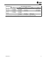
Voltage (V) Min. Waiting Time (Minutes)
4 15 20 30 40
200 - 240 1.5–5 hp
[1.1–3.7 kW]
7.5–60 hp
[5.5 –45 kW]
380 - 480 1.5–10 hp
[1.1–7.5 kW]
15–125 hp
[11–90 kW]
150–350 hp
[110–250 kW]
450–1350 hp
[315–1000 kW]
525-600 1.5–10 hp
[1.1–7.5 kW]
15–125 hp
[11–90 kW]
525-690 15–125 hp
[11–90 kW]
60–550 hp
[45–400 kW]
600–1875 hp
[450–1400 kW]
Be aware that there may be high voltage on the DC link even when the LEDs are turned off.
Safety
TR200 BACnet 1-5

Safety Precautions
WARNING
The voltage of the adjustable frequency drive is dangerous whenever connected to line power. Incorrect installation of
the motor, adjustable frequency drive or serial communication bus could cause death, serious personal injury or damage
to the equipment. Consequently, the instructions in this manual, as well as national and local rules and safety regula-
tions, must be complied with.
WARNING
Safety Regulations
1.
The line power supply to the adjustable frequency drive must be disconnected whenever repair work is to be
carried out. Make sure that the line power supply has been disconnected and that the necessary time has elapsed
before removing motor and line power supply plugs.
2.
The [OFF] button on the control panel of the adjustable frequency driver does not disconnect the line power supply
and consequently it must not be used as a safety switch.
3. The equipment must be properly grounded, the user must be protected against supply voltage and the motor must
be protected against overload in accordance with applicable national and local regulations.
4.
The ground leakage current exceeds 3.5 mA.
5.
Protection against motor overload is not included in the factory setting. If this function is desired, set par.
1-90
Motor Thermal Protection to data value ETR trip 1 [4] or data value ETR warning 1 [3].
6.
Do not remove the plugs for the motor and line power supply while the adjustable frequency drive is connected
to line power. Make sure that the line power supply has been disconnected and that the necessary time has elapsed
before removing motor and line power plugs.
7.
Please note that the adjustable frequency drive has more voltage sources than L1, L2 and L3, when load sharing
(linking of DC intermediate circuit) or external 24 V DC are installed. Make sure that all voltage sources have been
disconnected and that the necessary time has elapsed before commencing repair work.
Failure to follow recommendations could result in death or serious injury.
WARNING
Warning against unintended start
1.
The motor can be brought to a stop by means of digital commands, bus commands, references or a local stop,
while the adjustable frequency drive is connected to line power. If personal safety considerations (e.g., risk of
personal injury caused by contact with moving machine parts following an unintentional start) make it necessary
to ensure that no unintended start occurs, these stop functions are not sufficient. In such cases, the line power
supply must be disconnected or the
Safe Stop
function must be activated.
2.
The motor may start while setting the parameters. If this means that personal safety may be compromised (e.g.,
personal injury caused by contact with moving machine parts), motor starting must be prevented, for instance by
use of the
Safe Stop
function or secure disconnection of the motor connection.
3.
A motor that has been stopped with the line power supply connected, may start if faults occur in the electronics
of the adjustable frequency drive, through temporary overload or if a fault in the power supply grid or motor con-
nection is remedied. If unintended start must be prevented for personal safety reasons (e.g., risk of injury caused
by contact with moving machine parts), the normal stop functions of the adjustable frequency drive are not suffi-
cient. In such cases, the line power supply must be disconnected or the
Safe Stop
function must be activated.
Consequently, disconnect all electric power, including remote disconnects before servicing. Follow proper lockout/
tagout procedures to ensure the power cannot be inadvertently energized. Failure to follow recommendations could
result in death or serious injury.
Safety
1-6 TR200 BACnet

Disconnect all electric power, including remote disconnects before servicing. Follow proper lockout/tagout pro-
cedures to ensure the power cannot be inadvertently energized. Failure to follow recommendations could result
in death or serious injury.
1. Control signals from, or internally within, the adjustable frequency drive may in rare cases be activated in
error, be delayed or fail to occur entirely. When used in situations where safety is critical, e.g., when con-
trolling the electromagnetic brake function of a hoist application, these control signals must not be relied
on exclusively.
Note
When using the
Safe Stop
function, always follow the instructions in the
Safe Stop
section of the Design Guide.
WARNING
Disconnect all electric power, including remote disconnects. Follow proper lockout/tagout procedures to ensure the
power cannot be inadvertently energized. Use an appropriate voltmeter to verify that the unit is discharged. Failure to
disconnect power and ensure unit is discharged before servicing could result in death or serious injury.
Also make sure that other voltage inputs have been disconnected, such as external 24 V DC, load sharing (linkage of
DC intermediate circuit), as well as the motor connection for kinetic backup.
Systems where adjustable frequency drives are installed must, if necessary, be equipped with additional monitoring
and protective devices according to the valid safety regulations, e.g., law on mechanical tools, regulations for the
prevention of accidents, etc. Modifications on the adjustable frequency drives by means of the operating software are
allowed.
Failure to follow recommendations could result in death or serious injury.
Hoisting applications:
The adjustable frequency drive functions for controlling mechanical brakes cannot be considered as a primary
safety circuit. There must always be a redundancy for controlling external brakes.
Protection Mode
Once a hardware limit on motor current or DC link voltage is exceeded, the drive will enter “Protection mode”.
“Protection mode” means a change of the PWM modulation strategy and a low switching frequency to minimize
losses. This continues 10 sec after the last fault and increases the reliability and the robustness of the drive while
re-establishing full control of the motor.
In hoist applications, “Protection mode” is not usable because the drive will usually not be able to leave this
mode again, and therefore it will extend the time before activating the brake – which is not recommended.
"Protection mode” can be disabled by setting par.14-26
Trip Delay at Inverter Fault to zero, which means that
the drive will trip immediately if one of the hardware limits is exceeded.
Note
It is recommended to disable protection mode in hoisting applications (par.14-26
Trip Delay at Inverter Fault =
0).
Safety
TR200 BACnet 1-7

Before Commencing Repair Work
WARNING
Hazardous Voltage!
1.
Disconnect the adjustable frequency drive from line power.
2. Disconnect DC bus terminals 88 and 89
3.
Wait at least the time mentioned above in the section General Warning.
4.
Remove motor cable
Failure to follow recommendations could result in death or serious injury.
Special Conditions
Electrical ratings:
The rating indicated on the nameplate of the adjustable frequency drive is based on a typical 3-phase line power
supply within the specified voltage, current and temperature ranges, which are expected to be used in most
applications.
The adjustable frequency drives also support other special applications, which affect the electrical ratings of the
adjustable frequency drive.
Special conditions that affect the electrical ratings might be:
• Single phase applications.
• High temperature applications that require derating of the electrical ratings.
• Marine applications with more severe environmental conditions.
Other applications might also affect the electrical ratings.
Consult the relevant sections in this manual and in the for information about the electrical ratings.
Installation requirements:
The overall electrical safety of the adjustable frequency drive requires special installation considerations re-
garding:
• Fuses and circuit breakers for overcurrent and short-circuit protection
• Selection of power cables (line power, motor, brake, load sharing and relay)
• Grid configuration (grounded delta transformer leg, IT,TN, etc.)
• Safety of low-voltage ports (PELV conditions).
Consult the relevant clauses in these instructions and in the for information about the installation requirements.
Safety
1-8 TR200 BACnet

Introduction
Introduction
About this Manual
First time users can obtain the most essential information for quick installation and set-up in these chapters:
Introduction
How to Install
How to Configure the System
Application Example
For more detailed information including the full range of set-up options and diagnosis tools, refer to the chapters:
How to Control the TR200
How to Access TR200 Parameters
Parameters
Troubleshooting
Technical Overview
BACnet (Building Automation and Control Network) is an open data communications protocol, American Na-
tional Standard (ANSI/ASHRAE 135-1995). BACnet provides a means by which computer-based control equip-
ment from different manufacturers can work together. BACnet is designed to handle many types of building
controls, including HVAC, lighting, security, fire, access control, maintenance and waste management. BACnet
permits flexibility for expansion and different equipment combinations.
Conformance Classes, Function Groups and the PICS: Evaluating the capabilities of a BACnet device is poten-
tially a formidable task, given the great choice of objects, properties and services, which can be implemented,
as well as the fact that it is not necessary for every BACnet device to have a full BACnet implementation in order
to carry out its task. ASHRAE's BACnet Committee recognized this problem and responded with aids to evalu-
ation in the form of "Conformance Classes", "Function Groups" and the "Protocol Implementation Conformance
Statement" (PICS).
The BACnet protocol defines six levels of conformance classes, each of which specifies the minimum subset of
services implemented on the device. The lowest level, Conformance Class 1, requires only that the BACnet
device contain a device object and that it be able to execute (respond to) a ReadProperty service request. Each
successive conformance class level adds service requests that must be executable by the device, as well as the
service requests it must be able to initiate. Conformance Class 6 requires 21 types of service requests (of the 32
overall) to be implemented, of which 20 must be initiable and 17 executable. Conformance class thus provides
a measure of the device's ability to communicate.
Function groups specify a combination of objects and services necessary to carry out certain building automa-
tion functions. They are specified independently of conformance class, though the implementation of some of
the function groups automatically confers some conformance class higher than 1.
TR200 BACnet 2-1

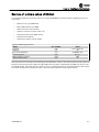
Background information
Protocol name: BACnet
Technology developer: ASHRAE
Year introduced: 1995
Governing standards: ANSI/ASHRAE Standard 135-2004, ISO 16484-5
Openness: Open specification
Physical characteristics
Network topology: Bus
Physical media: Shielded twisted pair
Max. Distance at low speed: 3937 ft [1200 m]
Transport mechanism
Communication methods: Master/slave
Baud Rates Supported: 9600, 19200, 38400, 76800
Termination: 120 ohm
Introduction
2-2 TR200 BACnet

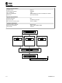
Assumptions
This manual assumes you are using a Trane BACnet Option Card in conjunction with a Trane TR200 series
adjustable frequency drive. It is also assumed that your master is a BMS or PC equipped with a serial commu-
nication card supporting all the BACnet communication services required by your application, and that all
requirements stipulated in the BACnet standard, as well as those pertaining to the Variable Frequency Drive are
strictly observed as well as all limitations therein fully respected.
Background Knowledge
The Trane BACnet Option Card is designed to communicate with any master complying with the BACnet stand-
ard. Familiarity with the PC or PLC used as a master in the system is assumed. Issues regarding hardware or
software produced by other manufacturers are beyond the scope of this manual and are not the responsibility
of Trane.
If you have questions regarding set-up of master-to-master communication or communication to a non-Trane
slave, consult the appropriate manuals.
Available Literature for TR200
- The Instruction Manual provides the necessary information for getting the drive up and running.
- Instruction Manual TR200 High Power
- The Design Guide contains all the technical information about the drive and customer design and applica-
tions.
- The Programming Guide provides information on how to program and includes complete parameter de-
scriptions.
x = Revision number
yy = Language code
Trane technical literature is available in print from your local Trane Sales Office or online at:
www.trane.com/vfd
Introduction
TR200 BACnet 2-3

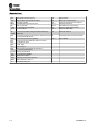
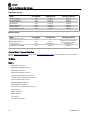
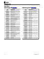
Abbreviations
ACI Acyclical Control Interval PCD Process Data
AOC Application Orientated Controller PCA Parameter Characteristics
AV Analog Variable PCV Parameter-Characteristics-Value
BMS Building Management System PDU Protocol Data Unit
BV Binary Variable PELV Protected Extra Low Voltage
CAN Controller Area Network PLC Programmable Logic Control
CTW Control Word PNU Parameter Number
EE-
PROM
Electrical Erasable Programmable Read Only
Memory
PVA Parameter Value
EIA Electronic Industries Association: Specifies of the
EIA Standard RS 485-A
RC Request/Response Characteristics
EMC Electromagnetic Compatibility STW Status Word
FDL Serial Communication Bus Data link Layer
FDT Field Device Tool
IND Sub index
I/O Input/Output
ISO International Standards Organization
LCD Liquid Crystal Display
keypad Local Control Panel
LED Light Emitting Diode
MAV Main Actual Value
MOC Motion Orientated Controller
MRV Main Reference Value
PC Personal Computer
Introduction
2-4 TR200 BACnet

How to Install
The BACnet Option
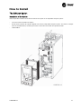
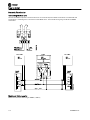
Installation of the Option
Items required to install a serial communication bus option in the adjustable frequency drive:
- The serial communication bus option
- Serial communication bus option adaptor frame for the adjustable frequency drive. This frame is deeper
than the standard frame, to allow space for the serial communication bus option beneath.
- Cable holders
TR200 BACnet 3-1

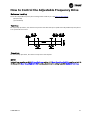
Instructions:
- Remove the keypad panel from the adjustable frequency drive.
- Remove the frame located beneath and discard.
- Push the option into place. Two positions are possible, with cable terminal facing either up or down. The
cable up position is often most suitable when several adjustable frequency drives are installed side by side
in a rack, as this position permits shorter cable lengths.
- Push the serial communication bus option adaptor frame for the adjustable frequency drive into place.
- Remove the plug for the Drive port and connect the plug that is connected to the BACnet option
- Replace the keypad panel.
- Attach cable.
- Fasten the cable in place using cable holders. The adjustable frequency drive top surface has pre-drilled
threaded holes for attaching the cable holders to the unit.
130BT341.10
Cabling
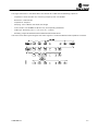
Cable lengths and number of nodes
The maximum cable length allowable in one segment is dependent on the transmission speed. The total cable
length includes drop cables if any. A drop cable is the connection from the main bus cable to each node. If a T-
connection is used, permissible cable length and maximum number of nodes/drives are 1, 2, 3 and 4 bus
segments.
Drop cable connection (i.e., T-connection) beyond the cable lengths indicated is not recommended, due to the
increased risk of reflection occurring. Instead, Trane recommends direct connection of the adjustable frequency
drive.
Note that a repeater is a node in both of the two segments it connects. The number of adjustable frequency
drives is based on a single master system. If there are two or more masters (e.g., PC tools, routers), the number
of adjustable frequency drives must be reduced correspondingly.
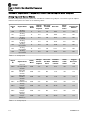
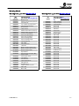
Network topology Maximum cable length
Free topology without repeater 1640 ft [500 m]
Free topology with one repeater 3280 ft [1000 m]
Free topology maximum device-to-device 1640 ft [500 m]
Bus topology single terminated 1640 ft [500 m]
Bus topology double terminated without repeater 8858 ft [2700 m]
Bus topology double terminated with one repeater 17716 ft [5400 m]
Bus topology maximum stub length 9.8 ft [3 m]
How to Install
3-2 TR200 BACnet

The length statements in the tables above are valid for bus cable with the following properties:
- Impedance: 135 to 165 Ohm at a measuring frequency from 3 to 20 MHz
- Resistance: <110 Ohm/km
- Capacitance: <30 pF/m
- Damping: max. 9 dB over the whole wire length
-
Cross section: max. 0.00053 in
2
[0.34 mm
2
], corresponding to AWG 22
- Cable type: twisted in pairs, 1 x 2, or 2 x 2, or 1 x 4 wires
- Shielding: Copper-braided shield or braided shield and foil shield
Use of the same cable type throughout the entire segment is recommended to avoid impedance mismatch.
How to Install
TR200 BACnet 3-3

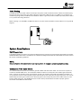
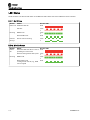
Network Termination
Connecting the Bus Line
Connect the BACnet Option Card to the bus line via terminals 62, 63 and 66. Terminal 62 is marked red and
Terminal 63 is marked green. These two are the RS485 lines. Terminal 66 the signal ground for the RS485
transmitter.
Maximum Cable Lengths
Maximum total bus cable length: 4000 ft [1200 m]
How to Install
3-4 TR200 BACnet

Cable Routing
The BACnet communication cable must be kept away from motor and brake resistor cables to avoid coupling
of high frequency noise from one cable to the other. Normally a distance of 7.9 in (200 mm) is sufficient, but
maintaining the greatest possible distance between cables is generally recommended, especially where cables
run in parallel over long distances.
When crossing is unavoidable, the BACnet cable must cross motor and brake resistor cables at an angle of 90
degrees.
System Specifications
EMC Precautions
The following EMC precautions are recommended to achieve interference-free operation of the BACnet network.
Additional EMC information is available in the
TR200 Drive Design Guide
. Also consult the BACnet master manual
for further installation guidelines.
NOTE
Ensure compliance with relevant national and local regulations, for example in protective ground connection.
Connection of the Cable Shield
It is recommended to connect the shield to ground at both ends of the bus cable. This ensures the optimum
resistance towards EMC noise. The shield of the BACnet cable must always be connected to ground at both
ends, meaning the shield must be connected to ground in all stations connected to the BACnet network. It is
very important to have a low impedance ground connection of the shield, also at high frequencies. This can be
obtained by connecting the surface of the shield to ground, for example by means of a cable clamp or a con-
ductive cable connector. The TR200 Series has various clamps and brackets to enable a proper ground
connection of the BACnet cable shield.
How to Install
TR200 BACnet 3-5
Page is loading ...
Page is loading ...
Page is loading ...
Page is loading ...
Page is loading ...
Page is loading ...
Page is loading ...
Page is loading ...
Page is loading ...
Page is loading ...
Page is loading ...
Page is loading ...
Page is loading ...
Page is loading ...
Page is loading ...
Page is loading ...
Page is loading ...
Page is loading ...
Page is loading ...
Page is loading ...
Page is loading ...
Page is loading ...
Page is loading ...
Page is loading ...
Page is loading ...
Page is loading ...
Page is loading ...
Page is loading ...
Page is loading ...
Page is loading ...
Page is loading ...
Page is loading ...
Page is loading ...
Page is loading ...
Page is loading ...
Page is loading ...
-
 1
1
-
 2
2
-
 3
3
-
 4
4
-
 5
5
-
 6
6
-
 7
7
-
 8
8
-
 9
9
-
 10
10
-
 11
11
-
 12
12
-
 13
13
-
 14
14
-
 15
15
-
 16
16
-
 17
17
-
 18
18
-
 19
19
-
 20
20
-
 21
21
-
 22
22
-
 23
23
-
 24
24
-
 25
25
-
 26
26
-
 27
27
-
 28
28
-
 29
29
-
 30
30
-
 31
31
-
 32
32
-
 33
33
-
 34
34
-
 35
35
-
 36
36
-
 37
37
-
 38
38
-
 39
39
-
 40
40
-
 41
41
-
 42
42
-
 43
43
-
 44
44
-
 45
45
-
 46
46
-
 47
47
-
 48
48
-
 49
49
-
 50
50
-
 51
51
-
 52
52
-
 53
53
-
 54
54
-
 55
55
-
 56
56


Ask a question and I''ll find the answer in the document
Finding information in a document is now easier with AI
Related papers
-
Trane TR200 Series Programming Manual
-
-
-
-
-
-
-
-
-
Other documents
-
Sinclair SBG-01 User manual
-
Mitsubishi Electric MELSEC iQ-R Series User manual
-
aci BACnet Outside Series Installation & Operation Instructions
-
LumenRadio W-BACnet User manual
-
 BACnet BACnet CFW-11 User manual
-
OPTO 22 BACnet MS/TP Integration Kit User guide
-
olympia electronics GR-7500 User manual
-
Ingersoll-Rand Trane Ascend ACS Installation, Operation and Maintenance Manual
-
WEG CFW300 User manual
-
WEG CFW100 User manual
