Page is loading ...

MULTI-ZONE
DUCTLESS INVERTER
SPLIT AIR CONDITIONER
WITH HEAT PUMP
•INSTALLATION
MANUAL•
UNIVERSAL FLOOR/CEILING
INDOOR UNIT
IMPORTANT NOTICE
• Read this manual carefully before
installing or operating your new air
conditioning unit. Make sure to save
this manual for future reference.


1
Installation Manual
1. PRECAUTIONS
The safety precautions listed here are divided into two categories.
After completing the installation, make sure that the unit operates
properly during the start-up operation. Instruct the customer on
how to operate and maintain the unit. Also, inform the
customer that he or she should store this manual with the user's
manual for future reference.
Only trained and qualified service personnel should
install, repair, or service the equipment.
Improper installation, repair, or maintenance may result in
electrical shock, short-circuiting, leaks, fire, or other
damage to the equipment.
CONTENTS
PAGE
PRECAUTIONS........................................................................................1
INSTALLATION INFORMATION. ..............................................................2
ATTACHED FITTINGS..............................................................................3
INSPECTING AND HANDLING THE UNIT.................................................4
INDOOR UNIT INSTALLATION. ...............................................................4
OUTDOOR UNIT INSTALLATION..............................................................6
CONNECT THE DRAIN PIPE.....................................................................8
INSTALL THE CONNECTING PIPE............................................................9
AIR EVACUATION..................................................................................12
WIRING.................................................................................................13
TEST OPERATION..................................................................................13
Install the unit strictly according to these installation
instructions.
If installation is done incorrectly, water leakage, electrical
shock, or fire may result.
To prevent refrigerant leakage when installing the unit in a
small room, do not allow refrigerant concentration to
exceed allowable safety limits.
Contact the place of purchase for more information.
Excessive refrigerant in a closed ambient can lead to oxygen
deficiency.
Use the attached accessories parts and specified parts
for installation.
If the wrong parts are used, set failure, water leakage, electrical
shock, or fire may result.
Install the unit at a strong, firm location that can
withstand the unit's weight.
If there is not enough support or the unit is not installed
properly, the unit may fall and cause injuries.
The appliance must not be installed in a laundry room.
Before obtaining access to terminals, disconnect all
supply circuits.
The appliance must be positioned so that the plug is
accessible.
The enclosure of the appliance must be marked, by word or
symbols, with the direction of the fluid flow.
For electrical work, follow the local national wiring
standard, regulations, and these installation instructions.
An independent circuit and single outlet must be used.
If the capacity of the electrical circuit is not large
enough or the electrical work is defective, electrical shock or
fire may result.
Use the specified cable, connect it tightly, and clamp the
cable so that no external force will affect the terminal.
If the connection or fixing is not perfect, overheating or fire will
occur at the connection.
Wiring routing must be properly arranged so that the
control board cover is fixed properly.
If the control board cover is not fixed perfectly,
overheating, electrical shock, or fire will occur at the
connection point of the terminal.
If the supply cord is damaged, it must be replaced by the
manufacturer, its service agent, or a similarly qualified
person to avoid a hazard.
In fixed wiring, an all-pole disconnection switch
with a contact separation of at least 3 mm in all
poles should be connected.
When connecting pipes, do not let air substances enter the
refrigeration cycle.
Otherwise, lower capacity, abnormal high pressure in the
refrigeration cycle, explosion, or injury may result.
Do not modify the length of the power supply cord or use an
extension cord, and do not share the single outlet with other
electrical appliances.
Otherwise, electrical shock or fire may result.
Carry out the specified installation work after taking into
account strong winds, typhoons, or earthquakes.
Improper installation work may cause the equipment to fall,
causing accidents.
CAUTION
WARNING
WARNING
Failure to follow these instructions exactly may result
in property damage, personal injury, or loss of life.
Failure to follow these instructions exactly may result in
minor or moderate property damage or personal
injury.
Keep this manual where the operator can easily find it.
Read this manual carefully before starting up the units.
For safety reasons, the operator must read the
following cautions carefully.
Installation must be performed by authorized personnel
only in accordance with NEC and CEC requirements
(applicable to North America only).

2
Installation Manual
To ensure proper installation, please read this installation
manual first.
The air conditioner must be installed by qualified persons.
When installing the indoor unit or its tubing, please follow
this manual as strictly as possible.
If the air conditioner is installed on a metal part of the
building, it must be electrically insulated according to the
relevant standards for electrical appliances.
When all the installation work is finished, conduct a
thorough check before turning on the power.
No announcement will be given if any change is made to
this manual due to product improvement.
2. INSTALLATION INFORMATION
Ground the air conditioner.
Do not connect the ground wire to gas or water pipes,
a lightning rod, or a telephone ground wire.
Inappropriate grounding may result in electrical shock.
Install an earth leakage breaker.
Failure to install an earth leakage breaker may result
in electrical shock.
Connect the outdoor unit wires, then connect the indoor
unit wires.
Do not connect the air conditioner with the power supply
until the wiring and piping is done.
While following the instructions in this
installation manual, install drain piping to ensure
proper drainage and insulate the piping to
prevent condensation.
Improper drain piping may result in water leakage and
property damage.
Install the indoor and outdoor units, power supply
wiring, and connecting wiring at least 1 meter away
from televisions or radios to prevent image
interference or noise.
Depending on the radio waves, a distance of 1 meter may not
be sufficient to eliminate noise.
The appliance is not intended for use by young children
or infirm persons without supervision.
Do not install the air conditioner in the
following circumstances or locations:
If petrolatum is nearby
If salty air is near the location (such as a coast)
If caustic gas (such as sulfide) is in the air (near a
hot spring)
If the volt vibrates violently (in factories)
In buses or cabinets
In a kitchen full of oil gas
If a strong electromagnetic wave is in the air
If inflammable materials or gas are nearby
If acid or alkaline liquid is evaporating nearby
If other special conditions exist
If the refrigerant leaks during installation, ventilate the
area immediately.
Toxic gas may be produced if the refrigerant comes into
contact with a source of fire.
The temperature of the refrigerant circuit will be high, so
keep the interconnection cable away from the
copper tube.
After completing the installation work, check that the
refrigerant does not leak.
Toxic gas may be produced if the refrigerant leaks into the
room and comes into contact with a source of fire, such as a
fan heater, stove, or cooker.
INSTALLATION ORDER
Select the location
Install the indoor unit
Install the outdoor unit
Install the connecting pipe
Connect the drain pipe
Install the wiring
Test the operation
CAUTION
The appliance must be installed in accordance
with national wiring regulations.
Do not operate your air conditioner in a wet room,
such as a bathroom or laundry room.
Use an all-pole disconnection device that has at least 3
mm clearance in all poles, a leakage current
thatexceeds 10mA, and a residual current device (RCD)
with a rated residual operating current not exceeding
30mA. The disconnection
must
be incorporated in the
fixed wiring
in accordance with wiring rules.

3
Installation Manual
3. ATTACHED FITTINGS
Ensure that the following fittings are of full scope. If there are spare fittings, restore them carefully.
QUANTITYSHAPENAME
5. User's manual
6. Installation manual
7. Remote control manual
1. Remote control
(on some models)
2. Remote control holder
(on some models)
4. Alkaline dry batteries (AM4)
1
1
2
2
1
1
Remote control and its holder
Others
3. Mounting screw (ST2.9×
10-C-H)
1

4
Installation Manual
Keep the indoor unit, outdoor unit, power supply wiring, and
transmission wiring at least 1 meter away from televisions and
radios. This is to prevent image interference and noise in those
electrical appliances. (Noise may be generated depending on the
conditions under which the electric wave is generated, even if a 1-
meter distance is maintained.)
5.2 Installing the main body
There is enough room for installation and maintenance.
The ceiling is horizontal and its structure can withstand
the weight of the indoor unit.
The inlet and outlet are not impeded, and the
influence of external air is small.
The airflow can extend throughout the room.
The connecting pipe and drain pipe can be easily
extracted.
There is no direct radiation from heaters.
5. INDOOR UNIT INSTALLATION
5.1 Installation place
(Refer to Fig. 5-1, Fig. 5-2 and Table 5-1 for specifications.)
The indoor unit should be installed in a location that meets
the following requirements:
4. INSPECTING AND HANDLING THE UNIT
At delivery, the package should be checked and any damage should
be reported immediately to the the service agent.
When handling the unit, take into account the following:
Fragile, handle the unit with care.
Keep the unit upright in order to avoid compressor
damage.
Choose beforehand the path along which the unit will be
brought in.
Move the unit in its original packaging as much as possible.
When lifting the unit, always use protectors to prevent belt
damage and pay attention to the position of the unit’s center
of gravity.
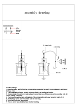
1
2
3
4
CAUTION
Fig. 5-1
≥ 35 mm
≥ 1000 mm
≥ 35 mm
≥ 35 mm
Fig. 5-2
Refer to Fig. 5-3 and Fig. 5-4 for the hanging screw bolts
distance.
Evaluate the ceiling construction and install with Ø 10
hanging screw bolts.
The handling to the ceiling will vary depending on the
construction. Consult the construction person for the specific
condition.
A Installing Ø 10 hanging screw bolts (4 bolts)
Keep the ceiling flat. Consolidate the roof beam to avoid
possible vibration.
Cut off the roof beam.
Strengthen the place that has been cut off and
consolidate the roof beam.
After the installation location is selected, position the refrigerant
pipes, drain pipes, and indoor and outdoor wires to the
connection places before hanging up the machine.
Install the hanging screw bolts.
Fig. 5-3
WOODEN CONSTRUCTION
Roof beam
Hanging screw bolts
Ceiling
Timber over the beam
Put the square timber traversely over the roof beam, then
install the hanging screw bolts.
B
E. Connecting point of
refrigerant pipe
(gas side)
D. Connecting point of
refrigerant pipe
(Liquid side)
Drain point
C
D
Hook

5
Installation Manual
3. Wall Mounting Installation
2. Ceiling Installation
Fig. 5-8
Locate the hanging arm on the hanging screw bolt.
(Refer to Fig. 5-9.)
Screw nut
Washer
Hanging
screw bolt
Hanging arm
Fig. 5-9
20~25mm
Hanging screw bolt
Hanging
bolts
Supporting
angle steel
STEEL ROOF BEAM STRUCTURE
Install and use the supporting angle steel.
B Installing the indoor unit
Fig. 5-4
Fig. 5-5
Fig. 5-6
Fig. 5-7
NEW CONCRETE BRICKS
FOR ORIGINAL CONCRETE BRICKS
Steel bar
Embedding screw bolt
(Pipe hanging and embedding screw bolt)
(Blade shape
insertion)
(Slide insertion)
Inlaying or embedding the screw bolts.
Install the hanging hook with an expansible bolt into the
concrete 45-50 mm deep to prevent the hook from coming
loose.
Remove the side board and the grille. (Refer to Fig. 5-8.)
Side board
Grille
Hanging arm
Hanging
screw bolt
20mm
The dimension of the unit
5.3
Table 5-1
unit:mm
Fig. 5-10
Fig. 5-11
Fig. 5-12
D. Connecting point
of refrigerant pipe
(gas side)
Drain point
Downward declivity lower between (1-2)/100
E. Connecting point of
refrigerant pipe
(liquid side)
MODEL
30-48
18-24
A B D EC
1068 675 235 983
60
220675 235 1565
1650
220
1285 675 235 1200
220
36-48
220675 235 1565
1650

6
Installation Manual
6. OUTDOOR UNIT INSTALLATION
Outdoor Unit Installation Instructions
Step 1: Select installation location
The outdoor unit should be installed in the location that
meets the following requirements:
Place the outdoor unit as close to the indoor unit as
possible.
Ensure that there is enough room for installation and
maintenance.
The air inlet and outlet must not be obstructed or
exposed to strong wind.
Ensure the location of the unit will not be subject to
snowdrifts, accumulation of leaves or other seasonal
debris. If possible, provide an awning for the unit.
Ensure the awning does not obstruct airflow.
The installation area must be dry and well ventilated.
There must be enough room to install the connecting
pipesandcablesandtoaccessthemformaintenance.
The area must be free of combustible gases and
chemicals.
The pipe length between the outdoor and indoor
unitTmVTU not exceed the maximum allowable pipe
length.
If possible, DO NOT install the unit where it XJMMCF
exposed to direct sunlight.
If possible, make sure the unit is located far away
from neighborJOH propertJFT so the noise fromthe
unit will not disturb PUIFST.
If the location is exposed to strong winds (for
example near a seaside), the unit TIPVME be placed
against B wall to shelter it from the wind. Ifnecessary,
use an awning. (See Fig. 6.1 BOE'JH 6.2)
Install the indoor and outdoor units, cables and wires
at least 1 meter from televisions or radios to prevent
static or image distortion. Depending on the radio
waves, a 1 meter distance may not be enough to
eliminate all interference.
Strong wind
Strong wind
Strong wind
Fig. 6.1 Fig. 6.2
Step 2: Install UIFoutdoor unit
Fix the outdoor unit with anchor bolts (M10)
> 60cm/23.6JO
Fix with bolts
CAUTION
U Be sure to remove any obstacles that
may block air circulation.
U Make sure you refer to Mength
Tpecifications to ensure there is
enoughroom for installation and
maintenance.
Fig. 6.3

7
Installation Manual
>120cm/47JO
Air Putlet
H
D
W
>30cm/11.8JO
Air inlet
Air inlet
Air inlet
Air inlet
(Wall or obstacle)
>30cm/11.8JO
>30cm/11.8JO
> 30cm/11.8JO
Table 6.1: Length Specifications of SplitType
Outdoor Unit (unit: mm/inch)
Table 6.2: Length Specifications of
Vertical Discharge Outdoor Unit (unit: mm/inch)
MODEL
DIMENSIONS
W H D
18
633/25 554/21.8554/21.8
24
633/25 554/21.8554/21.8
36
759/29.8 554/21.8554/21.8
36
633/25 600/23.6600/23.6
36
759/29.8 600/23.6600/23.6
36/48/60
759/29.8 710/28710/28
60 843/33 710/28710/28
SplitType Outdoor Unit
(Refer to 'JHVSFT 6.4, 6.5, 6.6, BOE6.10 and Table 6.1)
Vertical Discharge Type Outdoor Unit
(Refer to 'JHVSFT 6.7, 6.8, BOE6.9
(Wall or obstacle)
Fig. 6.7
Fig. 6.8
Fig. 6.9
Fig. 6.6
Fig. 6.5
A
B
D
W
H
W
H
Fig. 6.4
Outdoor Unit Dimensions
W x H x D
Mounting Dimensions
Distance A Distance B
760x590x285 (29.9x23.2x11.2) 530 (20.85) 290 (11.4)
810x558x310 (31.9x22x12.2) 549 (21.6) 325 (12.8)
845x700x320 (33.27x27.5x12.6) 560 (22) 335 (13.2)
900x860x315 (35.4x33.85x12.4) 590 (23.2) 333 (13.1)
945x810x395 (37.2x31.9x15.55) 640 (25.2) 405 (15.95)
990x965x345 (38.98x38x13.58) 624 (24.58) 366 (14.4)
946x810x420 (37.24x31.9x16.53) 673 (26.5)
403 (15.87)
946x810x410 (37.24x31.9x16.14) 673 (26.5)
403 (15.87)
952x1333x410 (37.5x52.5x16.14) 634 (24.96)
404 (15.9)
952x1333x415 (37.5x52.5x16.34) 634 (24.96)
404 (15.9)
845x702x363 (33.27x27.6x14.3)
540 (21.26)
350 (13.8)
938x1369x392 (36.93x53.9x15.43) 634 (24.96) 404 (15.9)
900x1170x350 (35.4x46x13.8) 590 (23.2) 378 (14.88)
800x554x333 (31.5x21.8x13.1) 514 (20.24) 340 (13.39)
and Table 6.2

8
Installation Manual
M
N
P
ll awk
c
a
b
m
o
r
f
”
8.
11/
mc 0
3
thgi
r
n
o
”
6.
32
/
mc0
6
60 cm / 2
3
.
6
”
a
b
o
v
e
tfe
l n
o
”
8.
11
/
mc
0
3
no r
fn
i
”
87 /
mc 0
0
2
t
Fig. 6.10
Drain Joint Installation
Before bolting the outdoor unit in place, install the drain
joint at the bottom of the unit. (See Fig. 6.11)
Fit the rubber seal on the end of the drain joint that
will connect to the outdoor unit.
Insert the drain joint into the hole in the base pan of
the unit.
Rotate the drain joint 90° until it clicks inUP place
facing the front of the unit.
Connect a drain hose extension (not included) tothe
drain joint to redirect water from the unit during
heating mode.
NOTE: Make sure the water drains to a safe location
where it will not cause water damage or a slipping
hazard.
Seal
Drain joint
(A)
(B)
Base pan hole
of UIFoutdoor
unit
Seal
Fig. 6.11
Notes Pn Drilling BHole Jn UIFWall
You must drill a hole in the wall for the refrigerant piping
and the signal cable that will connect the indoor and
outdoor units.
Determine the location of the wall hole based on the
location of the outdoor unit.
Using a 65mm (2.5JO) core drill, drill a hole in the
wall.
NOTE: When drilling the wall hole, make sure
to avoid wires, plumbing, and other sensitive
components.
3. Place the protective wall cuff in the hole. This
XJMMprotect the edges of the hole and will help
seal itwhen you finish the installation process.
NOTE:The minimum distance between the outdoor
unit and UIFwalls described in the installation guide
does not apply to airtight rooms. Be suSe to keep the
unit unobstructed in at least two of the three
directions (M, N, P) (See Fig. 6.10)
CAUTION
7. CONNECT THE DRAIN PIPE
Install the indoor unit's drain pipe
The outlet has a PTI screw bread. Use sealing materials and
a pipe sheath (fitting) when connecting the PVC pipes.
Drainage test
Ensure that the drainpipe is unhindered.
In a newly built house, this test should be
performed before the ceiling is paved.
The drain pipe and the connections of the indoor unit must be
heat insulated or they will condense dew.
A hard PVC binder must be used for pipe connection. Make
sure there is no leakage.
Do not impose pressure on the side of the indoor unit pipes.
When the declivity of the downward drain pipe is greater than
1/100, prevent winding.
When pulled out transversely, the total length of the drain pipe
must not exceed 20 m. If a pipe is unusually long, install a prop
stand to prevent winding.
Refer to Fig. 7-1 for the installation of the pipes.
1.5 m-2 m
Insulating
material
Downward declivity
lower t han 1/10 0
Bend
S shap e
VP30
Downw ard declivity
lower than 1/100
Put as deep as possible
(about 10 cm)
Fig. 7-1

9
Installation Manual
Safety Precautions
WARNING
U All field pipingmustbecompletedbyalicensed
technician and must comply with local and
nationalregulations.
U Whentheairconditionerisinstalledinasmall
room, measures must be taken to prevent the
refrigerant concentration in the room from
exceeding the safety limit in the event of
refrigerant leakage. If the refrigerant leaks andits
concentration exceeds its proper limit, hazards
due to lack of oxygen may result.
U Wheninstallingtherefrigerationsystem,ensure
that air, dust, moisture or foreign substances do
notenter the refrigerant circuit. Contaminationin
the system may cause poor operating capacity,
high pressure in the refrigeration cycle, explosion
or injury.
U Ventilatetheareaimmediatelyifthereis
refrigerant leakage during installation. Leaked
refrigerant gas is both toxic and flammable.
Ensure there is no refrigerant leakage after
completing the installation work.
NotesPnPipeLengthandElevation
Ensure that the length of the refrigerant pipe, the number
of bends, and the drop height between the indoor and
outdoor units meets the requirements shown in Table 8.1:
Table 8.1: The Maximum Length Bnd Drop
Height Based on Models (Vnit: m/ft.)
Type of model Capacity
(Btu/h)
Length of
piping
Maximum
drop height
50Hz T1
Condition/R22
Split Type
12K 15/49
8/26
18K24K 30/98.4
10/32.8
30K-42K
50/164
20/65.6
48K-60K
50/164
25/82
50HzVertical
Discharge, 60Hz
T1 condition/R22
SplitType,Vertical
Discharge
12K 15/49 8/26
18K-24K
30/98.4
10/32.8
30K-60K
30/98.4
20/65.6
R410A Inverter
Split Type
<15K 25/82
10/32.8
≥15K-<24K 30/98.4
20/65.6
≥24K-<36K
50/164
25/82
≥36K-≤60K
65/213
30/98.4
R410A Split Type
12K 15/49
8/26
18K-30K 25/82 15/49
36K 30/98.4
20/65.6
48K-60K
50/164
25/82
50Hz/60Hz T3
condition (outdoor
unit down)
18K-24K
35/114
10/32.8
30K 30/98.4
15/49
36K 30/98.4
20/65.6
42K-60K
50/164
25/82
50Hz/60Hz T3
Condition (outdoor
unit up)
18K-24K
25/82
15/49
30K 30/98.4
20/65.6
36K 30/98.4
25/82
42K 50/164
30/98.4
48K-60K
50/164
35/114
Unit with quick
joint
12K-18K 5/16.4 5/16.4
8. INSTALL THE CONNECTING PIPE

10
Installation Manual
Refrigerant Piping Connection Instructions
CAUTION
U The branching pipe must be installed horizontally.
An angle of more than 10° may cause malfunction.
U DO NOT install the connecting pipe until bothUIF
indoor and outdoor units have been installed.
U Insulate both the gas and liquid piping to prevent
water leakage.
Step1: Cut pipes
When preparing refrigerant pipes, take extra care
to cut and flare them properly. This will ensure
efficient operation and minimize the need for future
maintenance.
1. Measure the distance between the indoor and
outdoor units.
2. Using a pipe cutter, cut the pipe a little longer than
the measured distance.
CAUTION
DO NOT deform EBNBHF PS EFOU UIF pipe EVSJOH
cutting PS the heating efficiency of the unit XJMM CF
ESBTUJDBMMZSFEVDFE.
1. Make sure that the pipe is cut at a perfect 90°
angle. Refer to Fig. 8.1 for examples of bad cuts
Oblique
Rough
WarpeE
90°
Fig. 8.1
Step2:Removeburrs
Burrs can affect the airtight seal of UIFrefrigerant
piping connectionBOE must be completely removed.
1. Hold the pipe at a downward angle to prevent
burrs from falling into the pipe.
2. Using a reamer or deburring tool, remove all burrs
from the cut section of the pipe.
Pipe
Reamer
Point dow
n
Fig. 8.2
Step 3: Flare pipe ends
Proper flaring is essential GPS an airtight seal.
After removing burrs from UIFcut pipe, seal the
endswith PVC tape to prevent foreign materials
fromentering the pipe.
Sheath the pipe with insulating material.
Place flare nuts on both ends of UIFpipe. Make
surethey are facing in the right direction because
youcan’t put them or change their direction after
flaring. See Fig. 8.3
Flare nut
Copper pipe
Fig. 8.3
4 . When you’ re ready to perform flaring work,
remove the PVC tape from UIFends of UIFpipe.
5. Clamp the flare form on the end of the pipe. The
endof the pipe must extend beyond the flare form.
Flare form
Pipe
Fig. 8.4

11
Installation Manual
Place UIFflaring tool on the form.
Turn the handle of the flaring tool clockwise until
the pipe is fully flared. Flare the pipe in accordance
with the dimensions shown in 5able 8-2.
Table 8.2: PIPING EXTENSION BEYOND FLARE FORM
Pipe
gauge
Tightening
torque
Flare dimension
(A) (Unit: mm/Jn)
Flare shape
Min. Max.
Ø 6.4
14.2-17.2 N.m
(144-176 kgf.cm)
8.3/0.3 8.3/0.3
R0.4-0.8
54
°
±
2
90
°
±
4
A
Fig. 8.5
Ø 9.5
32.7-39.9 N.m
(333-407 kgf.cm)
12.4/0.48 12.4/0.48
Ø 12.7
49.5-60.3 N.m
(504-616 kgf.cm)
15.4/0.6 15.8/0.6
Ø 15.9
61.8-75.4 N.m
(630-770 kgf.cm)
18.6/0.7 19/0.74
Ø 19.1
97.2-118.6 N.m
(990-1210 kgf.
cm)
22.9/0.9 23.3/0.91
8. Remove the flaring tool and flare form, then inspect
the end of the pipe for cracks and even flaring.
Step 4: Connect pipes
Connect the copper pipes to the indoor unit first, then
connectit tothe outdoorunit.'Jrst connectthelow-
pressure pipe, then the high-pressure pipe.
1. When connecting the flare nuts, apply a thin coat
of refrigeration oil to the flared ends of the pipes.
2. Align the center of the two pipes that you will
connect.
Indoor unit tubing
Flare nut
Pipe
Fig. 8.6
3. Tighten the flare nut as tightly as possible by hand.
4. Using a spanner, grip the nut on the unit tubing.
5. While firmly gripping the nut, use a torque wrench
to tighten the flare nut according to the torque
values in table 8.2.
NOTE: Use both a spanner and a torque wrench when
connecting or disconnecting pipes to/from the unit.
Fig. 8.7
CAUTION
U
U
#FTVSF to wrap insulation around the piping. Direct
contact with the bare piping may result in burns or
frostbite.
Make sure the pipe is properly connected. Over
tightening may damage the bell mouth and under
tightening may lead to leakage.
NOTE ON MINIMUM BEND RADIUS
Carefully bend the tubing in the middle according to the
diagram below. DO NOT bend the tubing more than
90° or more than 3 times.
Bendthepipe withZPVSthumb
min-radius10cm (3.9JO
Fig. 8.8
6. After connecting the copper pipes to the indoor
unit, wrap the power cable, signal cable and
piping together with binding tape.
NOTE:8IJMFCVOEMJOHUIFTFJUFNTDO NOT intertwine
UIFsignal cable with other wires.
Thread this pipeline through the wall and connect
it to the outdoor unit.
Insulate all the piping, including the valves of the
outdoor unit.
Open the stop valves of the outdoor unit to start
the flow of the refrigerant between the indoor and
outdoor unitT.
CAUTION
.ake sure there is no refrigerant leak after the
installation workJTDPNQMFUF. If there is a refrigerant
leak, ventilate the area immediately and evacuate
the system (refer to the Air Evacuation section of this
manual).
Ø 22
109.5-133.7 N.m
(1117-1364 kgf.
cm)
27/1.06 27.3/1.07

12
Installation Manual
the added refrigerant according to the diameter and the
length of the liquid side pipe of the outdoor unit/indoor unit
connection.(suitable for throttle outdoor unit)
Table 9-1
Liquid tube (mm) R410A R22
Ø 6.35
Ø 9.52
Ø 12.7
Ø 15.9
Ø 19
0.022 kg/m×(L-5)
0.011 kg/m×(L-5)
0.060 kg/m×(L-5)
0.030 kg/m×(L-5)
0.110 kg/m×(L-5)
0.060 kg/m×(L-5)
0.170 kg/m×(L-5)
0.085 kg/m×(L-5)
0.250 kg/m×(L-5)
0.125 kg/m×(L-5)
0.030 kg/m×(L-5)
0.015 kg/m×L
0.065 kg/m×(L-5)
0.030 kg/m×L
0.115 kg/m×(L-5)
0.060 kg/m×L
0.190 kg/m×(L-5)
0.095 kg/m×L
0.290 kg/m×(L-5)
0.145 kg/m×L
orifice in the indoor unit
orifice in the outdoor unit
orifice in the outdoor unit
orifice in the outdoor unit
orifice in the outdoor unit
orifice in the outdoor unit
orifice in the indoor unit
orifice in the indoor unit
orifice in the indoor unit
orifice in the indoor unit
9. AIR EVACUATION
Safety Precautions
CAUTION
U Useavacuumpumpwithagaugereadinglower
than -0.1MPa and an air discharge capacity above
40L/min.
U Theoutdoorunitdoesnotneedvacuuming.DO
NOT open the outdoor unit’s gas and liquid stop
valves.
U EnsurethattheDompoundNeterreads-0.1MPaor
below after 2 hoursPGPQFSBUJPO. If after hoursthe
gauge reading is still above0.1MPa, check if there is
a gas leak or water insidethe pipe. If there is no
leakage, perform anotherevacuation for 1 or 2
hours.
U DO NOT use refrigerant gas to evacuate the
system.
Evacuation Instructions
Before using Bmanifold gauge and Bvacuum pump, read
their operation manuals to familiarize yourself with how to
use them properly.
Manifold Hauge
Compound gauge
-76cmHg
Lowpressure valve
Charge hose
Highpressure valve
Charge hose
Vacuum pump
Pressure gauge
Lowpressure valve
Fig. 9.1
Connect the charge hose of the manifold gauge toUIF
service port on the outdoor unit’s lowpressure valve.
Connect another charge hose from the manifold gauge
to the vacuum pump.
Open the MowQressure side of the manifold gauge.
Keep the IighQressure side closed.
Turn on the vacuum pump to evacuate the system.
Run the vacuum for at least 15 minutes, or until the
Dompound Neter reads -76cmHG (-1x10⁵Pa).
Close the MowQressure side of the manifold gauge and
turn off the vacuum pump.
Wait 5 minutes, then check that there has been no
change in system pressure.
NOTE:
The table above refers to the liquid tube.
The number of bends is up to the length of the max. height drop.
Usually a bend is necessary every 10 m.
If a negative result is achieved for R from Table 9-1, no refrigerant
needs to be added or removed.
Additional refrigerant will be twice R from Table 9-1 if the indoor
unit installed throttle assembly.
NOTE: If there is no change in system pressure, unscrew
the cap from the packed valve (highpressure valve). If
there is a change in system pressure, there may be a gas
leak.
Note Pn Adding Refrigerant
8. Insert Bhexagonal wrench into the packed valve (high
pressure valve) and open the valve by turning the
wrench in a 1/4 counterclockwise turn. Listen for gas to
exit the system, then close the valve after 5 seconds.
Flare nut
Cap
Valve body
Valve stem
Fig. 9.2
Watch the Qressure Hauge for minute to FOsurethere
is no change in pressure. The Qressure Haugeshould
read slightly higher than UIFatmospheric pressure.
Remove the charge hose from the service port.
Using Bhexagonal wrench, fully open both the high
pressure and lowpressure valves.
OPEN VALVE STEMS GENTLY
When opening UIFvalve stems, turn the hexagonal
wrenchuntil it hits against the stopper.DO NOT try to
force the valve to open further.
12.Tighten UIFvalve caps by hand, then tighten UIFN using
the proper tool.
CAUTION
U Refrigerantchargingmustbeperformedafterwiring,
vacuumingandtheleaktest.
U DO NOT exceed the maximum allowable quantityof
refrigerant or overcharge the system. Doing socan
damage or impact the unit’s function.
U Chargingwithunsuitablesubstancesmaycause
explosionsoraccidents.Ensurethattheappropriate
refrigerantisused.
U Refrigerantcontainersmustbeopenedslowly.Always
useprotectivegearwhenchargingthesystem.
U DO NOT mix refrigerants types.
The outdoor unit is factory charged with refrigerant. Calculate

13
Installation Manual
10. WIRING
Connect the connective cables to the terminals as identified
by their respective numbers on the terminal block of the
indoor and outdoor units.
Reinstall the cover or the protection board.
Connect the cable
10.1
10.2
Specification of Power
(Refer to Tables 10-1 to 10-8.)
10.3
Wiring figure
(Refer to Figures 10-3 to 10-6.)
Remove the PVUEPPSVOJUhTelectric coverIf there is no
cover on the outdoor unit, disassemble the bolts from
the maintenance board and remove the protection
board. (See Fig. 10.1BOE 10.2)
Cover
Screw
Fig. 10.1
Protection Coard
Fig. 10.2
NOTE:
Remark per EMC Directive 2004/108/EC.
To prevent flicker impressions during the start of the
compressor (technical process), take note of the following
installation conditions:
1. The air conditioner's power must be connected at the main
power distribution. The distribution must be of a low impedance.
Normally the required impedance reaches a 32 A fusing point.
2. No other equipment should be connected with this power line.
3. Refer to your power supplier to see if restrictions apply for
products like washing machines, air conditioners, or electric
ovens.
4. For power details concerning your air conditioner, refer to the
product's rating plate.
5. Contact your local dealer with any questions.
The appliance must be installed in accordance with national
wiring regulations.
The air conditioner should use a separate power supply
with rated voltage.
The external power supply to the air conditioner should
have ground wiring that is linked to the ground wiring of the
indoor and outdoor units.
The wiring should be performed by qualified persons
according to the circuit drawing.
An all-pole disconnection device that has at least 3 mm
separation distance in all poles and a residual current
device (RCD) with a rating above 10 mA must be
incorporated in the fixed wiring according to the national
rule.
Be sure to carefully locate the power wiring and the signal
wring to avoid cross-disturbance.
After the wiring is complete, the power should not be turned
on until the wiring has been carefully checked.
The power cord type designation is H07RN-F.
a. There are no vibrations or abnormal noises during
operation
b. No wind, noise, or condensation generated by the air
conditioner have influenced your neighborhood
c. No refrigerant has leaked
A protection feature prevents the air conditioner from
activating for approximately 3 minutes when it is
restarted immediately after shutting off.
CAUTION
1) The indoor unit
a. The switch on the remote control works well
b. The buttons on the remote control work well
c. The airflow louver moves normally
d. The room temperature is adjusted well
e. The indicator lights normally
f. The temporary buttons work well
g. Drainage is normal
h. There is no vibration or abnormal noise during
operation
I. The air conditioner heats well (HEATING/COOLING
models only)
2) The outdoor unit
4
11. TEST OPERATION
The test operation must be carried out after the entire
installation has been completed.
Please confirm the following points before the test operation:
2
1
According to the user's requirement, install the
remote control frame where the remote control's signal
can reach the indoor unit smoothly.
Test operation
Set the air conditioner to "COOLING" mode with the remote
control and check the following points. If there is any
malfunction, resolve it according to the Troubleshooting
chapter in the User's Manual.
3
The indoor unit and outdoor units are installed properly
Tubing and wiring are correctly completed
The refrigerant pipe system was checked for leakage
The drainage is unimpeded
The heating insulation works well
The ground wiring is connected correctly
The length of the tubing and the added stow capacity of
the refrigerant have been recorded
The power voltage fits the rated voltage of the air
conditioner
There is no obstacle at the outlet or inlet of the outdoor or
indoor units
The gas side and liquid side stop valves are both open
The air conditioner is preheated

14
Installation Manual
Table 10-1
Table 10-2
The Specification of Power (Indoor Power Supply)
The Specification of Power (Outdoor Power Supply)
20/16 40/25 50/30 60/45 60/50
40/30
60/40
70/55 70/60
MODEL
POWER
CIRCUIT BREAKER/FUSE (A)
PHASE
FREQUENCY AND VOLT
18 24 60
30-36 42-48
208-240 V 208-2 40 V
1Phase 1Phase
208-2 40 V
1Phase
208-2 40 V
1Phase
208-2 40 V
1Phase
MODEL
POWER
CIRCUIT BREAKER/FUSE (A)
PHASE
FREQUENCY AND VOLT
30-36 30-36
42-60 42-60
380-420V
25/20
25/20
40/25 45/35
208-2 40 V
3 Pha se
380-420V
3Phase 3 Phase
208-2 40 V
3Phase
Table 10-3
Table 10-4
MODEL
POWER
CIRCUIT BREAKER/FUSE (A)
PHASE
FREQUENCY AND VOLT
24
60
30-36 42-48
208-2 40 V
1Phase
20/16
12-18
208-2 40 V
1Phase
208-2 40 V
1Phase
208-2 40 V
1Phase
208-2 40 V
1Phase
MODEL
POWER
CIRCUIT BREAKER/FUSE (A)
PHASE
FREQUENCY AND VOLT
30-36 30-36
42-60 42-60
380-420V
25/20 25/20 40/25 45/35
208-2 40 V
3 Phase
380-420V
3Phase
3Phase
208-2 40 V
3Phase

15
Installation Manual
The Specification of Power (Independent Power Supply)
20/16 40/25
50/30
60/45 60/50
208-240 V 208-2 40 V
1Phase
1Phase
208-2 40 V
1Phase
208-2 40 V
1Phase
208-2 40 V
1Phase
MODEL
POWER
(indoor)
POWER
(outdoor)
POWER
(indoor)
POWER
(outdoor)
CIRCUIT BREAKER/FUSE (A)
CIRCUIT BREAKER/FUSE (A)
PHASE
FREQUENCY AND VOLT
PHASE
FREQUENCY AND VOLT
18 24 60
30-36 42-48
208-240 V 208-2 40 V
1Phase 1Phase
208-2 40 V
1Phase
208-2 40 V
1Phase
208-2 40 V
1Phase
20/16 20/16 20/16 20/16 20/16
208-2 40 V
1Phase
208-2 40 V
1Phase
208-2 40 V
1Phase
208-2 40 V
1Phase
20/16 20/16 20/16 20/16
MODEL
CIRCUIT BREAKER/FUSE (A)
CIRCUIT BREAKER/FUSE (A)
PHASE
FREQUENCY AND VOLT
30-36 30-36
42-60 42-60
380-420V
25/20 25/20 40/25 45/35
208-2 40 V
3Phase
380-420 V
3Phase
3Phase
208-2 40 V
3Phase
Table 10-5
Table 10-6
PHASE
FREQUENCY AND VOLT
POWER
(indoor)
POWER
(outdoor)
30/20 30/20 40/30 40/35 50/40
208-240 V 208-2 40 V
1Phase
1Phase
208-2 40 V
1Phase
208-2 40 V
1Phase
208-2 40 V
1Phase
MODEL
POWER
(indoor)
POWER
(outdoor)
POWER
(indoor)
POWER
(outdoor)
CIRCUIT BREAKER/FUSE (A)
CIRCUIT BREAKER/FUSE (A)
PHASE
FREQUENCY AND VOLT
PHASE
FREQUENCY AND VOLT
18 24 60
30-36 42-48
220-240 V 220-2 40 V
1Phase
1Phase
220-2 40 V
1Phase
220-2 40 V
1Phase
220-2 40 V
1Phase
15/10 15/10 15/10 15/10 15/10
220-2 40 V
1Phase
220-2 40 V
1Phase
220-2 40 V
1Phase
220-2 40 V
1Phase
15/10
15/10 15/10
15/10
MODEL
CIRCUIT BREAKER/FUSE (A)
CIRCUIT BREAKER/FUSE (A)
PHASE
FREQUENCY AND VOLT
30-36 30-36
42-60 42-60
380-420V
30/20 30/25 50/40 50/40
208-2 40 V
3Phase
380-420V
3Phase
3Phase
208-2 40 V
3Phase
The Specification of Power for the Invert-Type Air Conditioner (Independent Power Supply)
Table 10-7
Table 10-8
PHASE
FREQUENCY AND VOLT
POWER
(indoor)
POWER
(outdoor)

16
Installation Manual
The power supply mentioned above can be applied to the table. Before accessing the
terminals, disconnect all supply circuits.
CAUTION
Wiring Figure
Fig. 10-3
Fig. 10-4
Ground wiring
Ground wiring
Power supply
Switch/fuse
(available locally)
Power wiring (indoor)
Power link wiring (outdoor)
Strong elec-signal link wiring
Weak elec-signal link wiring
Indoor
Unit
Outdoor
Unit
Ground the air conditioner properly to enhance the anti-interference function
Ground wiring
Ground wiring
Power supply
Switch/fuse
(available locally)
Power wiring (outdoor)
Power link wiring (indoor)
Strong elec-signal link wiring
Weak elec-signal link wiring
Indoor
Unit
Outdoor
Unit
Ground the air conditioner properly to enhance the anti-interference function

17
Installation Manual
Fig. 10-5
Ground wiring
Power supply
Switch/fuse
(available locally)
Power wiring (indoor)
Power link wiring (outdoor)
Ground wiring
Weak elec-signal link wiring
Indoor
Unit
Outdoor
Unit
Power supply
Ground the air conditioner properly to enhance the anti-interference function
A disconnection device with an air gap contact separation in all active conductors should be
incorporated in the fixed wiring according to the National Wiring Regulation.
When wiring, choose the corresponding chart to avoid damage. The signs of the indoor terminal block
in some of the following figures may be replaced by L N L1 N1.
CAUTION
Fig. 10-6
Ground wiring
Ground wiring
Power supply
Switch/fuse
(available locally)
Power wiring (outdoor)
Strong elec-signal link wiring
Weak elec-signal link wiring
Indoor
Unit
Outdoor
Unit
Ground the air conditioner properly to enhance the anti-interference function

The design and specications are subject to change without prior notice for product
improvement. Consult the sales agency or manufacturer for details.
/