ETC Source Four Revolution User manual
- Category
- Stroboscopes & disco lights
- Type
- User manual

User Manual
For all Revolutions manufactured prior to May, 2007 (7160A1002).
Rev E
August 2008
© Copyright 2007. Electronic Theatre Controls, Inc.
All rights reserved.
Product information and specifications subject to change.
Part Number:
7160M1200
Rev E
Released: August 2008
For Revolutions manufactured May, 2007 or after (7160A1017), see Revolution User Manual 7160M1210.
The Source Four Revolution high performance automated ellipsoidal spotlight is intended for professional
use only. Read entire User Manual before using equipment.

ETC, Source Four, Revolution, and QXL are registered trademarks of Electronic Theatre
Controls, Inc. in the United States and other countries.
Other product and company names mentioned herein may be trademarks and/or service marks
of their respective owners.
The Source Four Revolution fixture is protected by one or more of the following patents, and
other pending patent applications worldwide:
US Patent # 6,628,089 B2, 6,932,491, 6,979,106, 6,902,302, 6,939,026, 6,903,531, 7,033,047
and US Design Patent #D477,885 S
USRE36,316
GB05952589
DE0592589
JP2,501772
Patents Pending
ACCREDITATIONS AND RECOGNITIONS (from ETL SEMKO : www.usa.etlsemko.com
)
ETL SEMKO is recognized by OSHA in the U.S. as a Nationally Recognized Testing Laboratory.
ETL tests to standards developed or approved by the American National Standards Institute
(ANSI), Underwriters Laboratories (UL) and others. Other notable accreditations include the
American Association of Laboratories Accreditations (A2LA), American National Standards
Institute (ANST), International Conference of Building Officials (ICBO), and the International
Electrotechnical Commission of Electrical Equipment (IECEE). ETL also has accreditations and
recognitions from around the globe. Visit www.etlsemko.com/accred.html
for a complete listing.

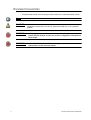
Table of Contents i
Table of Contents
Specifications . . . . . . . . . . . . . . . . . . . . ii
Overview . . . . . . . . . . . . . . . . . . . . . . . .1
Document Conventions . . . . . . . . . . . . . . . . . . . . . . . . . . . . .2
Safety . . . . . . . . . . . . . . . . . . . . . . . . . . . . . . . . . . . . . . . . . .3
Installation . . . . . . . . . . . . . . . . . . . . . . . . . . . . . . . . . . . . . . .4
Power and Data cabling requirements . . . . . . . . . . . . . .4
Installation procedures . . . . . . . . . . . . . . . . . . . . . . . . . 5
Connections and Addressing . . . . . . . . . . . . . . . . . . . . 8
Power-up Procedure and Calibration . . . . . . . . . . . . . . 9
Power-down Procedure . . . . . . . . . . . . . . . . . . . . . . . . .9
Control . . . . . . . . . . . . . . . . . . . . . . . . . . . . . . . . . . . . 10
Control Values for the Standard 12-Color Gel String . 11
Reset Channel . . . . . . . . . . . . . . . . . . . . . . . . . . . . . . .11
Timing Channels. . . . . . . . . . . . . . . . . . . . . . . . . . . . . 12
Configuration. . . . . . . . . . . . . . . . . . . .13
Removing and Replacing Modules . . . . . . . . . . . . . . . . . . .14
Blank Module (BM) . . . . . . . . . . . . . . . . . . . . . . . . . . . . . . .15
Iris Module (IM) . . . . . . . . . . . . . . . . . . . . . . . . . . . . . . . . . .16
Shutter Module (SM) . . . . . . . . . . . . . . . . . . . . . . . . . . . . . .17
Static Wheel Module (SWM) . . . . . . . . . . . . . . . . . . . . . . . .18
Controlling the Static Wheel Module. . . . . . . . . . . . . . .18
Rotating Wheel Module (RWM). . . . . . . . . . . . . . . . . . . . . .19
Controlling the Rotating Wheel Module . . . . . . . . . . . 20
Replacing Gobos and Filters . . . . . . . . . . . . . . . . . . . . . . . .21
Routine Maintenance . . . . . . . . . . . . .23
Procedures . . . . . . . . . . . . . . . . . . . . . . . . . . . . . . . . . . . . .24
Scroller Cartridges and Beam Containment Devices . .24
Gel Strings . . . . . . . . . . . . . . . . . . . . . . . . . . . . . . . . . .25
Internal Media Frame (IMF) . . . . . . . . . . . . . . . . . . . . 27
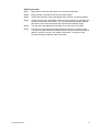
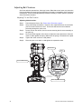
Changing and Adjusting the Lamp . . . . . . . . . . . . . . . 30
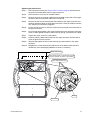
Adjusting Belt Tensions . . . . . . . . . . . . . . . . . . . . . . . 32
Troubleshooting. . . . . . . . . . . . . . . . . . . . . . . . . . . . . . . . . .38
LED Indicators . . . . . . . . . . . . . . . . . . . . . . . . . . . . . . .38
Internal Test Software. . . . . . . . . . . . . . . . . . . . . . . . . 39
Photometric Data . . . . . . . . . . . . . . . .43

ii Source Four Revolution User Manual
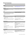
Specifications
Physical
• Die cast aluminum construction • High strength yoke for hanging in any orientation
• Rugged plastic covers for field-serviceable areas • See Dimensions and Hanging Clearances, page 6
• CE compliant and ETL tested to UL 1573 standards • See Fixture Weight, page 7
Electrical
• 100V-240VAC, 50/60Hz
• Power input via PowerCon
®
connector
• Electronics and internal dimmer are auto-ranging for
world-wide use
Lamp
• QXL™ 750W/77V Maximum
• Ultra compact tungsten filament geometry contained in
a Krypton/Xenon quartz envelope
• QXL - Quick eXchange Lamp provides one-handed
replacement in seconds and disconnects lamp power
automatically (Patent Pending)
Optical
• 15° - 35° zoom range
• 90% of infrared (I/R heat) removed from projected light
beam
• Dual aspheric zoom lens system with deposition
anti-reflective coating
• Reflector secured with anti-vibration shock mounts
• Faceted borosilicate reflector with multi-layer dichroic
coating
• Low gate and beam temperature
• 95% of visible light reflected through the optical train
• Tool-free lamp centering (X/Y) and peak/flat (Z)
adjustment knobs
Standard Features
• Integral Pulse Width Modulated 0-77 VAC Dimmer
• Integral 20-frame color scroller with a quick-change
scroller cartridge, ships with the ETC 12-color standard
gel string
• 540° Pan / 270° Tilt • Accessory slot with retainer
• Zoom Optics
• Internal Media Frame for insertion of diffusion or color
media into beam
• Soft to crisp focus for gobos
• Two module bays for the tool-free addition of optional
features
• QuietDrive™ low-noise motor control technology
(Patent Pending)
• Rotary switch address assignment requires no fixture
power for addressing, allows access to internal test
functions
• Advanced cooling design for ultra-quiet operation • DMX512-A compliant
Optional Modules
• Auto-sensing plug-and-play modules for additional
features
• Static Wheel Module - three positions plus open for M-
size glass or metal gobos and filters
• Iris Module - for beam size control down to 2.5°
• Rotating Wheel Module - three positions plus open for
M-size glass or metal gobos and filters, indexes with
16-bit accuracy
• Shutter Module - four blades with 90° rotation for full-
function framing

Overview 1
Overview
Congratulations on your purchase of the Source Four
®
Revolution™ fixture. Source Four
Revolution has been engineered for maximum performance with minimum cost.
The Source Four Revolution fixture is a modular, automated ellipsoidal reflector spotlight.
The base model includes zoom optics, a color scroller with a standard gel scroll, blank
modules and the internal media frame for diffusion media or color correction. Optional
modules include the iris module, the shutter module, the static wheel and rotating wheel
modules which can be fitted with gobos or dichroic color filters.
If you have questions about your Source Four Revolution fixture that are not answered in
this manual, please contact the supplier of your ETC equipment or ETC Technical Services.
Please email comments about this manual to: TechComm@etcconnect.com
Americas United Kingdom
Electronic Theatre Controls Inc. Electronic Theatre Controls Ltd.
Technical Services Department Technical Services Department
3031 Pleasant View Road 26-28 Victoria Industrial Estate
Middleton, WI 53562 Victoria Road,
800-775-4382 (USA, toll-free) London W3 6UU England
+1-608 831-4116 +44 (0)20 8896 1000
[email protected] service@etceurope.com
Asia Germany
Electronic Theatre Controls Asia, Ltd. Electronic Theatre Controls GmbH
Technical Services Department Technical Services Department
Room 1801, 18/F Ohmstrasse 3
Tower 1, Phase 1 Enterprise Square 83607 Holzkirchen, Germany
9 Sheung Yuet Road +49 (80 24) 47 00-0
Kowloon Bay, Kowloon, Hong Kong [email protected]
+852 2799 1220

2 Source Four Revolution User Manual
Document Conventions
Throughout this manual, the following are used to alert you to notes and safety notices.
Note:
Notes are helpful hints and information that is supplemental to the main text.
CAUTION:
A Caution statement indicates situations where there may be undefined or
unwanted consequences of an action, potential for data loss or an equipment
problem.
WARNING:
A Warning statement indicates situations where damage may occur,
people may be harmed, or there are serious or dangerous consequences
of an action.
WARNING:
RISK OF ELECTRIC SHOCK! This warning statement indicates situations
where there is a risk of electric shock.

Overview 3
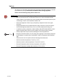
Safety
The Source Four Revolution high performance automated ellipsoidal spotlight is intended
for professional use only. Read entire User Manual before using equipment.
Please note the following safety notices before use:
WARNING:
Note the following safety warnings before use:
• Do not mount the Source Four Revolution fixture on or near a flammable surface.
• Use the fixture in dry locations only, where humidity does not exceed 90 percent (non-
condensing). Fixture is not intended for outdoor use.
• Mount and support the fixture only by the primary suspension holes in the upper
enclosure.
• Suspend the fixture from a suitable structure using a minimum of two hook clamps
secured with tightened steel bolts (12 mm (1/2") Ø), washers and locking nuts.
• In addition to primary suspension, attach a safety cable (ETC Model 400SC or other
approved safety cable or device) to the handles of the fixture’s upper enclosure.
• Always replace the lamp if it becomes damaged or thermally deformed.
• Keep the luminaire at least 0.7m (28") away from anything it is illuminating. Objects lit
at this distance or greater will not exceed 90°C (194°F) temperature from projected
light.
• Disconnect the unit from power before all cleaning and maintenance.
• Maximum ambient temperature: Ta=45°C (113°F)
• Maximum exterior surface temperature: T
m
ax=270°C (518°F)
• External Temperature after 5 minutes of operation: 35°C (95°F)
• External Temperature (steady state achieved): 270°C (518°F)
0.7m

4 Source Four Revolution User Manual
Installation
Power and Data cabling requirements
The Source Four Revolution fixture operates on AC power, 100-240VAC/50-60Hz, and
consumes a maximum of 900 watts. You may use a circuit powered through an SCR
dimmer, as long as the dimmer is set to unregulated non-dim (switched) operation.
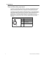
The Source Four Revolution operates on DMX control signal. The unit is supplied with a
5-pin XLR DMX input connector and a 5-pin DMX Thru connector. DMX cables should be
acceptable for DMX data transmission (not microphone cable) and should follow the
standard pinout. The optional secondary data pair is not used by the Source Four
Revolution fixture. On pre-2007 fixtures, termination is required after the last fixture on a
DMX data line. Revolutions built in 2007 or later are equipped with self-terminating
connectors.
DMX512 pinout for five-pin XLR female
1 Common (Shield)
2 Data –
3 Data +
4 not connected
5 not connected
Push
1
2
3
4
5

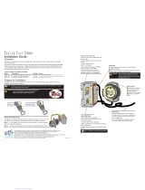
Overview 5
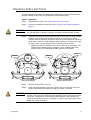
Installation procedures
Installing hanging hardware
The Source Four Revolution fixture’s upper enclosure provides six bolt holes for installation
of hanging hardware. Suspend the fixture from a suitable structure using a minimum of two
hook clamps secured with tightened steel bolts (12 mm (1/2”) Ø), washers and locking nuts.
330mm (13.0”)
295mm (11.6”)
123mm (4.85”)
246mm (9.7”)
123mm (4.85”)

6 Source Four Revolution User Manual
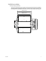
Dimensions and Hanging Clearances
344mm
(13.5")
317mm
(12.5")
454mm
(17.9")
394mm
(15.5")
400mm
(15.7")
619mm
(24.4")
116mm
(4.6")
856mm
(33.7")
1
2
3
4
5
6
7
8
9
1
2
3
4
5
6
7
8
9
1
2
3
4
5
6
7
8
9
I
O
762mm
(30.0")
775mm
(30.5")
713mm
(28.1")
856mm
(33.7")
1
2
3
4
5
6
7
8
9
1
2
3
4
5
6
7
8
9
1
2
3
4
5
6
7
8
1
2
3
4
5
6
7
8
9
1
2
3
4
5
6
7
8
9
1
2
3
4
5
6
7
8
I
O
I
O
Distance between
upper enclosure
and pipe is
variable (hanging
hardware
dependent).

Overview 7
Safety Cable
The safety cable (or other approved safety device) should be secured to one of the handles
on the upper enclosure, wrapped around the hanging structure (pipe), then secured to the
other handle on the upper enclosure. Take care to leave as little slack as possible in the
safety cable to avoid the cable catching the yoke of the fixture.
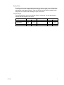
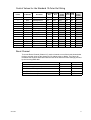
Fixture Weight
Total weight depends on how the individual fixture is configured. Use the table below to
calculate the total weight of your fixture.
Device Weight Device Weight
Base Fixture 74 lb 33.6 kg Static Wheel Module 3 lb 1.4 kg
Blank Module 1.8 lb 0.7 kg
Rotating Wheel
Module
3.7 lb 1.7 kg
Iris Module 3 lb 1.4 kg Shutter Module 10.4 lb 4.7 kg

8 Source Four Revolution User Manual
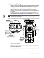
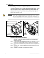
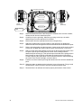
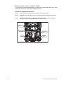
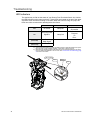
Connections and Addressing
Connect AC input power and DMX data cables to the appropriate ports as shown below.
Connect the incoming DMX data cable to the DMX Input connector. If you are daisy-
chaining the data to other fixtures or DMX-controlled devices, connect the next DMX cable
to the DMX Thru connector. Revolutions built prior to 2007 (Part Number 7160A1002)
require that the last fixture on a DMX line be terminated with a 100Ω resistor between pins
2 and 3. Revolutions built in 2007 or after are self-terminating and do not require
termination. If both types are used on the same DMX line, it is recommended that the line
be terminated.
Use the three thumbwheels on the upper enclosure to set the starting address for the
fixture. Addresses must be set between 1-481. The fixture will report an error if the address
is set to 482 or above. See Control, page 10, for channel mapping.
Note:
Revolution is a 31-channel fixture. A fixture with a starting address higher than 481 will
not have control of all parameters.
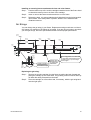
Connect the AC Input cable:
Align and insert the power connector. Twist the connector clockwise until it locks into place.
Disconnect the AC Input cable:
Slide back the locking tab, twist the connector counterclockwise and pull to unlock and
disconnect the power connector.
I
O
I
O
1
2
3
4
5
6
7
8
9
1
2
3
4
5
6
7
8
9
1
2
3
4
5
6
7
8
9
1
2
3
4
5
6
7
8
1
2
3
4
5
6
7
8
1
2
3
4
5
6
7
8
AC Input
(Neutrik
®
PowerCon
®
connector)
Power Switch and
Breaker
DMX Input
DMX Thru
Thumbwheels
Front Bay
Rear Bay
Tilt Lock
Pan Lock
LEDs

Overview 9
Power-up Procedure and Calibration
Move the power switch/breaker to the “on” position to apply power to the fixture.
CAUTION:
The Source Four Revolution fixture is provided with pan and tilt locks for your
convenience when working on the fixture. The pan lock is located on the upper
enclosure and the tilt lock is located on the tilt side yoke leg. Ensure that the pan
and tilt locks are disengaged before applying power to your fixture.
On power-up, the fixture will perform a series of movements to calibrate its motorized
functions. Once the calibration process has completed, the fixture’s motors will end in the
position determined by the incoming DMX signal. If no signal is present, the fixture’s
functions will rest at the position of a DMX level of zero.
Power-down Procedure
Move the power switch/breaker to the “off” position.
It is recommended that you allow the fixture to run for at least five minutes with the lamp off
prior to removing power.
CAUTION:
If you are packing-up your fixture for travel, do not pack the fixture with the yoke
against the pan stop, or with the pan and tilt lock engaged. Pan and tilt locks
are provided for fixture maintenance only and are not to be engaged during
shipment. This will damage the end stop(s) and will prevent your fixture from
calibrating correctly in the future.

10 Source Four Revolution User Manual
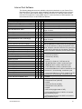
Control
The Source Four Revolution fixture can take as few as 14 and up to 31 DMX channels to
operate. The table below describes the order and function of each address, as well as
which parameters are affected by the timing channels.
Timing channels give you the option to have the fixture calculate parameter movement over
time, instead of using DMX fades and cue timing. Using timing channels may produce
smoother movement of parameters (see Timing Channels, page 12).
Fixture personalities can be found at ETC’s website: www.etcconnect.com
DMX Base Unit Base + Modules Base + Framing
Timing
Channel
1 Intensity Intensity Intensity
2 Pan (Coarse) Pan (Coarse) Pan (Coarse) F
3 Pan (Fine) Pan (Fine) Pan (Fine) F
4 Tilt (Coarse) Tilt (Coarse) Tilt (Coarse) F
5 Tilt (Fine) Tilt (Fine) Tilt (Fine) F
6 Internal Media Frame Internal Media Frame Internal Media Frame
7 Focus Focus Focus B
8 Zoom Zoom Zoom B
9 Focus Timing (F) Focus Timing (F) Focus Timing (F)
10 Color Timing (C) Color Timing (C) Color Timing (C)
11 Beam Timing (B) Beam Timing (B) Beam Timing (B)
12 Reset Reset Reset
13 Gel Scroller Gel Scroller Gel Scroller C
14 Fan Speed Control Fan Speed Control Fan Speed Control
15 Iris Iris B
16 Front Bay Wheel Position Front Bay Wheel Position B
17 Front Bay Wheel Function Front Bay Wheel Function B
18
Front Bay Wheel Index/
Rotation (Coarse)
Front Bay Wheel Index/
Rotation (Coarse)
B
19
Front Bay Wheel Index/
Rotation (Fine)
Front Bay Wheel Index/
Rotation (Fine)
B
20 Rear Bay Wheel Position Reserved B
21 Rear Bay Wheel Function* Reserved B
22
Rear Bay Wheel Index/
Rotation (Coarse)
a
a) Prolonged use of the Rotating Wheel Module in the Rear Bay may cause the belt within the module to degrade. To
ensure peak performance of the RWM, use it in the Front Bay.
Reserved B
23
Rear Bay Wheel Index/
Rotation (Fine)
a
Reserved B
24 #1 Shutter In B
25 #1 Shutter Rotate B
26 #2 Shutter In B
27 #2 Shutter Rotate B
28 #3 Shutter In B
29 #3 Shutter Rotate B
30 #4 Shutter In B
31 #4 Shutter Rotate B

Overview 11
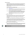
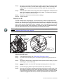
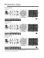
Control Values for the Standard 12-Color Gel String
Reset Channel
To use the Reset Channel (Channel 12), set the channel to one of the levels shown below
for three seconds, then set the channel to 0% without timing or fading. The fixture will
recalibrate the functions associated with the reset level and return to the settings provided
by the incoming DMX data.
Frame
Gel Number
a
a) R = Roscolux and Rosco Supergel numbers, L = Lee.
Gel Name
Percent
Start
Percent
End
Percent
Center
Frame
DMX
Start
DMX
End
DMX
Center
Frame
0 (Leader) — Open White 0% 7% 3% 0 17 9
1 R02 Bastard Amber 7% 14%
11% 18 36 27
2 R05 Rose Tint 15% 21%
18% 37 54 46
3 R09 Pale Amber Gold 22% 28%
25% 55 72 64
4 R54 Special Lavender 29% 35%
32% 73 90 82
5 R357 Royal Lavender 36% 43%
39% 91 109 100
6 R36 Medium Pink 43% 50%
46% 110 127 119
7 R25 Orange Red 50% 57%
54% 128 145 137
8 L203 1/4 C.T. Blue 57% 64%
61% 146 164 155
9 L201 Full C.T. Blue 65% 71%
68% 165 182 174
10 R68 Sky Blue 72% 78%
75% 183 200 192
11 R88 Light Green 79% 85%
82% 201 218 210
12 L-HT115 Peacock Blue 86% 93%
89% 219 237 228
13 (Trailer) — Open White 93% 100%
97% 238 255 247
Reset Function DMX Percent DMX Decimal
Reset entire fixture 75 185-190
Reset scroller and lenses only 60 147-152
Reset Pan and Tilt only 50 126-129
Reset Front Module only 40 97-102
Reset Rear Module only 30 72-77

12 Source Four Revolution User Manual
Timing Channels
Three timing channels are provided: Focus Timing (Channel 9), Color Timing (Channel 10),
and Beam Timing (Channel 11). These channels can be used to communicate the desired
duration of a movement at the same time you communicate the destination of the
movement. The instructions below describe the general method of using a timing channel.
Specific instructions for recording cue fade times or part cues can be found in your control
console’s user manual.
Using timing channels to set parameter timing:
Step 1: Determine which timing channel controls the parameters you want to affect (see
Control, page 10).
Step 2: Set the timing channel to the appropriate value. Each step of DMX equals one
second of time. Percent-based consoles will have a granularity of ~2.5 seconds
per step. The maximum timing value is 4 minutes 15 seconds.
Step 3: Record the parameter channels and their corresponding timing channel into a
cue or cue part with zero fade timing. Avoid placing timing channel moves within
a cue or cue part that contains a fade time other than zero. Fading a timing
channel and its corresponding parameter channels can create unexpected
luminaire behavior.
Step 4: Repeat for other parameter channels and timing channels as needed.
Fan Speed Control Channel
The Fan Speed Control Channel (Channel 14) allows fan speed control for quieter fixture
operation. As long as this channel is at 0%, all fans will run at full speed for maximum
cooling. Setting this channel at incrementally higher values lowers the fan speed
incrementally.
For example, 25% = 75% fan speed, 50% = 50% fan speed, 75% = 25% fan speed, and so
on. Setting this channel at 100% will turn the fans off completely for silent operation.
Temperature sensors in the Revolution sense if fans are required to keep the fixture from
an over-temperature condition. These sensors override the fan speed channel and cause
the fans to operate to prevent over-heating, regardless of the channel setting.
For longer gel string life—especially saturated colors—keep the fan speed as high as
possible, that is, a lower value for channel 14.
Using Focus Timing for Console Response Option
Setting the Focus Timing Channel (Channel 9) at 100% provides more responsive manual
control of Revolution parameters. Remember to restore this channel to 0% (or the desired
timing speed value less than 100%) for smoothest cue playback operation.
Note:
Playback of cues with the Focus Channel set at 100% may result in less than satisfactory
luminaire movement.

Configuration 13
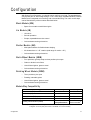
Configuration
With Source Four Revolution, you decide how to configure your light. The standard base
unit provides pan, tilt, beam-edge change, 15-35° zoom range, two Blank Modules, Internal
Media Frame, integrated color scrolling, and on-board dimming. The unit’s module bays
can be filled with any of the modules described below.
Blank Module (BM)
• Space for one static metal M-sized gobo
Iris Module (IM)
• 18-leaf iris
• Smooth operation
• Simple, repeatable beam-size control
• On-board auto-sensing electronics
Shutter Module (SM)
• Multi-plane shutters for flexible beam shaping
• All shutters have +/– 45° rotation (total range of motion = 90°)
• On-board auto-sensing electronics
Static Wheel Module (SWM)
• Four positions, typically setup as three positions plus open
• Gobos or dichroic color filters
• Uses M-sized gobos, glass or metal
• On-board auto-sensing electronics
Rotating Wheel Module (RWM)
• Three positions, plus open
• Rotating, indexable gobos
• Uses M-sized gobos, glass or metal
• On-board auto-sensing electronics
Module/Bay Compatibility
Module Type Front Bay Rear Bay
Blank Module (BM) Yes Yes
Iris Module (IM) Yes Yes
Shutter Module (SM) No Yes
Static Wheel Module (SWM) Yes Yes
Rotating Wheel Module (RWM)
Recommended for
best performance
Not
Recommended
a
a) Prolonged use of the Rotating Wheel Module in the Rear Bay may cause the belt within the module
to degrade. To ensure peak performance of the RWM, use it in the Front Bay.

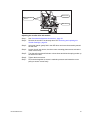
14 Source Four Revolution User Manual
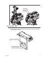
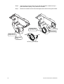
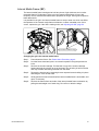
Removing and Replacing Modules
Each module is secured with two thumbscrews. See the diagram below for bay designation.
Remove a module:
Step 1: Power-down the fixture. See Power-down Procedure, page 9.
CAUTION:
Screws securing the modules may be hot if the fixture has recently been lit.
Step 2: Loosen the two screws securing the module by turning them to the left
(counterclockwise).
Step 3: Pull the module gently out of the head of the fixture.
Insert a module:
Step 1: Align the module in the selected bay with the interface connector closest to the
center bay divider.
Step 2: Guide the module gently into the bay making certain that the guide posts of the
module housing are properly aligned with the accommodating hole in the fixture
frame. Ensure that the module seats on the control card.
Step 3: Tighten the screws securing the module by turning them to the right (clockwise).
Ensure that the screws are tightened completely.
CAUTION:
Prolonged use of the Rotating Wheel Module in the rear bay may cause the belt
within the module to degrade. To ensure peak performance of the RWM, use it in
the Front Bay.
Shutter Modules must be placed only in the rear bay. Shutter module installation also
must include mounting the counterweight frame that came with the revolution in the front
of the unit. See Shutter Module (SM), page 17.

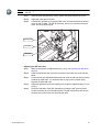
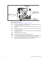
Configuration 15
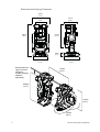
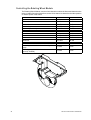
Blank Module (BM)
The Blank Module is used to fill an empty module bay, and can be used to hold a static
M-Size metal gobo, if needed.
Front Bay
Rear Bay
Pull gently to remove
and insert metal gobos.
M-Size metal gobos only.

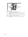
16 Source Four Revolution User Manual
Iris Module (IM)
The Iris Module contains an 18-leaf iris and can be placed in either module bay.
Page is loading ...
Page is loading ...
Page is loading ...
Page is loading ...
Page is loading ...
Page is loading ...
Page is loading ...
Page is loading ...
Page is loading ...
Page is loading ...
Page is loading ...
Page is loading ...
Page is loading ...
Page is loading ...
Page is loading ...
Page is loading ...
Page is loading ...
Page is loading ...
Page is loading ...
Page is loading ...
Page is loading ...
Page is loading ...
Page is loading ...
Page is loading ...
Page is loading ...
Page is loading ...
Page is loading ...
Page is loading ...
-
 1
1
-
 2
2
-
 3
3
-
 4
4
-
 5
5
-
 6
6
-
 7
7
-
 8
8
-
 9
9
-
 10
10
-
 11
11
-
 12
12
-
 13
13
-
 14
14
-
 15
15
-
 16
16
-
 17
17
-
 18
18
-
 19
19
-
 20
20
-
 21
21
-
 22
22
-
 23
23
-
 24
24
-
 25
25
-
 26
26
-
 27
27
-
 28
28
-
 29
29
-
 30
30
-
 31
31
-
 32
32
-
 33
33
-
 34
34
-
 35
35
-
 36
36
-
 37
37
-
 38
38
-
 39
39
-
 40
40
-
 41
41
-
 42
42
-
 43
43
-
 44
44
-
 45
45
-
 46
46
-
 47
47
-
 48
48


ETC Source Four Revolution User manual
- Category
- Stroboscopes & disco lights
- Type
- User manual
Ask a question and I''ll find the answer in the document
Finding information in a document is now easier with AI
Related papers
-
ETC Source Four Revolution User manual
-
-
-
-
-
-
-
-
-
Other documents
-
Monacor DLT-125 User manual
-
-
Max Load 35913 User manual
-
Extron RWM 1 Template
-
 Halo Lighting System L2756P User manual
-
 Source Four S4Dim-S4 Installation guide
-
 INCOM Life Safe 8226730 Owner's manual
-
 INCOM Life Safe 8226821 Owner's manual
-
Lightolier 2029 Series User manual
-
High End Systems x.Spot Xtreme User manual


