Page is loading ...

Report No. 216-S-38b-6.5
MODEL #CSK-25
HUSSONG MFG. CO., INC.
INSTALLATION AND OPERATION MANUAL
INSTALLER: Leave this manual with the appliance.
CONSUMER: Retain this manual for future reference.
This appliance may be installed in an
aŌermarket, permanently located,
manufactured home (USA only) or mobile
home, where not prohibited by local codes.
This appliance is only for use with the type of
gas indicated on the raƟng plate. This
appliance is not converƟble for use with other
gases, unless a cerƟfied kit is used.
Do not store or use gasoline or other
flammable vapors and liquids in the vicinity
of this or any other appliance.
WHAT TO DO IF YOU SMELL GAS
Do not try to light any appliance.
Do not touch any electrical switch; do not
use any phone in your building.
Immediately call gas supplier from a
neighbors phone. Follow the gas supplier
instrucƟons.
If you cannot reach your gas supplier, call
the fire department.
InstallaƟon and service must be performed
by a qualified installer, service agency or the
gas supplier.
WARNING: If the informaƟon in these
instrucƟons are not followed exactly, a fire or
explosion may result causing property
damage, personal injury, or loss of life.
English and French installaƟon manuals available through
your local dealer, or visit our website www.kozyheat.com
Abarrierdesignedtoreducetheriskofburnsfromthehotviewingglassis
providedwiththisapplianceandshallbeinstalled.
WARNING
HOT GLASS WILLCAUSEBURNS.
DO NOT TOUCH GLASS UNTILCOOLED.
NEVER ALLOWCHILDRENTOTOUCHGLASS.
CSK-25 ● REV-03 ● November 2014
DIRECT VENT GAS FIREPLACE INSERT

1
CONGRATULATIONS!
We welcome you as a new owner of a Kozy Heat gas fireplace. Kozy Heat products are designed with
superior components and materials; assembled by trained craftsmen who take pride in their work. The
burner and valve assembly are 100% test-fired, and the complete fireplace is thoroughly inspected before
packaging to ensure you receive a quality product. Our commitment to quality and customer satisfaction
has remained the same for over 30 years. We offer a complete line of gas and wood fireplaces, unique
cabinets and stylish accessories to complement any décor. Adding a fireplace is one of the best ways to
increase the value of your home, and we are proud to offer a network of dealers throughout the country to
help make your experience everything you imagine. We pride ourselves in being dedicated not only to
functionality and reliability, but also customer safety. We offer our continual support and guidance to help
you achieve the maximum benefit and enjoyment from your Kozy Heat gas fireplace.
Read this manual before installing or operating this appliance.
Please retain this owner’s manual for future reference.
Dudley Hussong
Board Chairman
Jim Hussong
President
Homeowner Reference Information
We recommend you record the following information:
Model Name: Date purchased/installed:
Serial Number: Location of fireplace:
Dealership purchased from: Dealer Phone:
Notes:

2
HOMEOWNER REFERENCE INFORMATION 1
TABLE OF CONTENTS
2
1.0 INTRODUCTION
3
1.1
Appliance Certification
3
1.2
Safety Information
3
1.3
Commonwealth of Massachusetts Requirements
4
2.0 SPECIFICATIONS
5
2.1
Components
5
2.2 Heating Specifications 6
2.3
High Altitude Installations
6
2.4
Appliance Dimensions
6
2.5
Assembly Overview
6
3.0 CLEARANCES 8
3.1 Placement Clearance Requirements
8
3.2 Appliance Clearances
8
4.0 EXISTING FIREPLACE REQUIREMENTS
9
4.1 Existing Fireplace and Chimney Specifications
9
5.0 INSTALLATION
10
5.1 Prepare Existing Fireplace
10
5.2 Fireplace Air Duct Removal
10
5.3 Combustion Air Venting Options
10
5.4 Kozy Heat #816-CL Co-Linear Vent System
11
5.5 Run Vent System Through Existing Chimney
12
5.6 Vent System Connection
13
6.0 GAS LINE CONNECTION
14
6.1 Gas Conversion
14
6.2 Gas Line Installation
14
7.0
WIRING SCHEMATICS 15
8.0
FIREPLACE INSERT SETUP 16
8.1 Glass Frame Assembly 16
8.2 Safety Barriers 16
8.3 ZC Shroud Assembly and Installation 18
8.4 Upper Hood and Lower Louver 18
8.5 #CXS-500 Log Set Installation 19
8.6 Control Board Removal and Installation 20
9.0 CONTROL SYSTEM
21
9.1 Control System Components
21
9.2 Control System Operation
22
10.0 LIGHTING AND SHUTDOWN
27
10.1 Operating Instructions
28
10.2 To Turn Gas Off to Appliance
28
11.0 FINALIZING THE INSTALLATION
29
11.1 Pressure Testing
29
11.2 Burner Tube Venturi Adjustment
30
12.0 TROUBLESHOOTING
31
12.1 Pilot Will Not Light / Stay Lit
31
12.2 Pilot Flame Always On / Will not Extinguish
31
12.3 Main Flame Will Not Light
31
12.4 Pilot and Burner Extinguish While in Operation
32
12.5 Glass Sooting
32
12.6 Flame Burns Blue and Lifts Off Burner
32
12.7 No Reaction to Command
32
13.0 MAINTENANCE
33
13.1 Burner and Pilot System 33
13.2 Fan
33
13.3 Vent System
33
13.4 Glass Assembly
33
14.0 REPLACEMENT PARTS LIST
34
LIMITED WARRANTY
35
LIFETIME WARRANTY
36
TABLE OF CONTENTS
R.(# of revision) and a straight line indicates updated information.
R.03
R.03
R.03

3
Installation and repair should be done only by a qualified service person. The appliance should be inspected by a
qualified service person before use. Annual inspection by a qualified service person is required to maintain warranty.
More frequent cleaning may be required due to excessive lint from carpeting, bedding materials, etc. It is imperative
that control compartments, burners, and circulation air passageways of the appliance be kept clean.
This fireplace insert is to be installed into a solid fuel masonry or factory built non-combustible fireplace that been
installed in accordance with the national, provincial, state, and local codes.
Children and adults should be alerted to the hazards of high surface temperatures and should stay away to avoid
burns or clothing ignition.
Young children should be carefully supervised when they are in the same room as the appliance. Toddlers, young
children, and others may be susceptible to accidental contact burns. A physical barrier is recommended if there are at-
risk individuals in the house. To restrict access to a fireplace or stove, install an adjustable safety gate to keep
toddlers, young children, and other at-risk individuals out of the room and away from hot surfaces.
Clothing or other flammable material should not be placed on or near the appliance.
Adequate accessibility clearances for servicing and proper operation must be maintained.
This appliance must not share, or be connected, to a chimney flue serving any other appliance.
Keep area around the appliance clear of combustible materials, gasoline, and other flammable vapor and liquids.
The flow of combustion and ventilation air must not be obstructed.
Due to high temperatures, the appliance should be located out of traffic and away from furniture and draperies.
The glass front, or any part removed for servicing the appliance, must be replaced prior to operating the appliance.
Work should be done by a qualified service technician.
Clean glass only when cool and only with non-abrasive cleansers.
WARNING: DO NOT OPERATE APPLIANCE WITH THE GLASS/FRAME ASSEMBLY REMOVED, CRACKED, OR
BROKEN. REPLACEMENT OF THE GLASS SHOULD ONLY BE PERFORMED BY A LICENSED OR
QUALIFIED SERVICE PERSON.
The glass assembly, Part #CXS-057T, shall only be replaced as a complete unit, as supplied by Hussong Mfg. Co., Inc.
DO NOT SUBSTITUTE MATERIALS.
Do not strike or slam glass assembly.
A safety barrier designed to reduce the risk of burns from the hot viewing glass is provided with this appliance and
shall be installed.
Any safety screen, guard, or barrier removed for servicing the appliance must be replaced prior to operating the
appliance.
If the safety barrier becomes damaged, the barrier shall be replaced with the manufacturer’s barrier for this appliance.
For use only with the following safety barriers: part numbers #CXS-PSF, #CXSA-PSF, #CXSA-MSF, or #CXS-RSF.
Under no circumstances should any solid fuel (wood, coal, paper, cardboard, etc.) be used in this appliance.
Keep burner and control compartment clean.
Do not use this fireplace if any part has been under water. Immediately call a qualified service technician to inspect
this appliance and to replace any part of the control system and any gas control which has been under water.
This appliance has been tested by OMNI-Test Laboratories located in Portland, Oregon and complies with:
ANSI Z21.88a-2012/CSA 2.33a-2012, “Vented Gas Fireplace Heaters”
CGA 2.17-M91 (R2009), “Gas-Fired Appliances for Use at High Altitudes”
CSA P.4.1-2009, “Testing Method for Measuring Annual Fireplace Efficiency”
This installation must conform with local codes, or in the absence of local codes, with the National Fuel Gas Code, ANSI Z223.1/NFPA
54, or the Natural Gas and Propane Installation Code, CSA B149.1.
This appliance, when installed, must be electrically grounded in accordance with local codes, or in the absence of local codes, with the
National Electrical Code, ANSI/NFPA 70, or the Canadian Electrical Code, CSA C22.1.
1.0 INTRODUCTION
1.1 Appliance Certification
1.2 Safety Information
R.03

4
1.3.1 Installation of Carbon Monoxide Detectors
At time of installation of side wall horizontally vented gas fueled equipment, the installing plumber or gas-fitter shall observe that a hard wired
carbon monoxide detector with an alarm and battery back-up is installed on the floor level where the gas equipment is to be installed. In addition,
the installing plumber or gas-fitter shall observe that a battery operated or hard wired carbon monoxide detector is installed on each additional level
of the dwelling, building or structure served by the side wall horizontal vented gas fueled equipment. It shall be the responsibility of the property
owner to secure the services of qualified licensed professionals for the installation of hard wired carbon monoxide detectors.
In the event that the side wall horizontally vented gas fueled equipment is installed in a crawl space or attic, the hard wired carbon monoxide
detector with alarm and battery back-up may be installed on the next adjacent floor level.
In the event that the requirements of this subdivision can not be met at the time of completion of installation, the owner shall have a period of thirty
(30) days to comply with the above requirements; provided, however, that during said thirty (30) day period, a battery operated carbon monoxide
detector with an alarm shall be installed.
1.3.2 Approved Carbon Monoxide Detectors
Each carbon monoxide detector as required in accordance with the above provisions shall comply with NFPA 720 and be ANSI/UL 2034 listed and
IAS certified.
1.3.3 Signage
A metal or plastic identification plate shall be permanently mounted to the exterior of the building at a minimum of eight (8) feet above grade direct-
ly in line with the exhaust vent terminal for the horizontally vented gas fueled heating appliance or equipment. The sign shall read, in print no less
the one-half inch (1/2) in size, “GAS VENT DIRECTLY BELOW. KEEP CLEAR OF ALL OBSTRUCTIONS”.
1.3.4 Inspection
The state or local gas inspector of the side wall horizontally vented gas fueled equipment shall not approve the installation unless, upon inspec-
tion ,the inspector observes carbon monoxide detectors and signage installed in accordance with the provisions of 248 CMR 5.08 (2) (a) 1 through
4.
1.3.5 Exemptions
The following equipment is exempt from 248 CMR 5.08 (2) (a) 1 through 4:The equipment listed in Chapter 10 entitled “Equipment Not Required
To Be Vented” in the most current edition of NFPA 54 as adopted by the Board; and Product Approved side wall horizontally vented gas fueled
equipment installed in a room or structure separate from the dwelling, building or structure used in whole or in part for residential purposes.
When the manufacturer of Product Approved side wall horizontally vented gas equipment provides a venting system design or venting system
components with the equipment, the instructions provided by the manufacturer for installation of the equipment and the venting system shall
include:
Detailed instructions for the installation of the venting system design or the venting system components; and
A complete parts list for the venting system design or venting system.
When the manufacturer of Product Approved side wall horizontally vented gas equipment does not provide the parts for venting the flue gases, but
identifies “special venting systems”, the following requirements shall be satisfied by the manufacturer:
The referenced “special venting systems” instructions shall be included with the appliance or equipment installation instructions and;
The “special venting systems” shall be Product Approved by the Board, and the instructions for that system shall include a parts list and
detailed installation instructions.
A copy of all installation instructions for all Product Approved side wall horizontally vented gas fueled equipment, all venting instructions, all parts
lists for venting instructions, and/or all venting design instructions shall remain with the appliance or equipment at the completion of the installation.
Gas Equipment Venting System Provided
Gas Equipment Venting System Not Provided
1.3.6 Manufacturer Requirements
The following requirements reference various Massachusetts and national codes not contained in this manual.
For all sidewall horizontally vented gas fueled equipment installed in every dwelling, building or structure used in whole or in part for
residential purposes, including those owned or operated by the Commonwealth and where the side wall exhaust vent termination is less
than (7) feet above finished grade in the area of the venting, including but not limited to decks and porches, the following requirements
shall be satisfied:
1.3 Commonwealth of Massachusetts Requirements

5
PART NUMBER DESCRIPTION
CXS-150 Control Board Assembly
700-203 Manual Gas Shut-off Valve
CXS-135 Burner Assembly
CXS-I900 Firebrick Refractory Set
CXS-500 Log Package
CXS-057T Glass Frame Assembly
CXS-028-IPI Fan Kit (1)-75 CFM
500-CXS Grill Assembly
700-408 Remote Control Transmitter
2.0 SPECIFICATIONS
2.1 Components
2.1.2 Additional Components Required
Approved Vent Systems
Kozy Heat Co-Linear Vent System, part number #816-CL.
For use with minimum 6” x 8” I.D. masonry or 7” I.D. Class A metal chimneys.
Includes 12 ft. (3.66 m) compressed, expandable co-linear 3” x 3” flexible chimney, and termination cap.
OTHER APPROVED VENTING SYSTEMS: ICC, Selkirk, American Metals (AmeriVent), Simpson Dura-Vent
2.3 High Altitude Installations
ATTENTION
USA: The appliance may be installed at higher altitudes. Please refer to your American Gas Association guidelines
which state the sea level rated input of Gas Designed Appliances installed at elevations above 2,000 ft. (610 m) is to be reduced
4% for each 1,000 ft. (305 m) above sea level. Refer also to National Fuel Gas Code, ANSI Z223.1 / NFPA 54, local authorities, or
codes which have jurisdiction in your area regarding the de-rate guidelines.
Canada: When the appliance is installed at elevations above 4,500 ft. (1,372 m), the certified high altitude rating shall be
reduced at the rate of 4% for each additional 1,000 ft. (305 m). Refer also to CSA-B149.1 Natural Gas and Propane Installation
Code, local authorities, or codes which have jurisdiction in your area regarding the de-rate guidelines.
2.2 Heating Specifications
Fuel
Minimum Input
BTU/hr. (kW)
Maximum Input
BTU/hr. (kW)
Orifice
Size
Natural Gas 13,500 BTU/hr (3.96 kW) 26,000 BTU/hr (7.62 kW) #44
LP Gas
13,000 BTU/hr (3.81kW) 25,500 BTU/hr (7.47 kW) #54
CSK-25
Manifold Pressure
(Low)
1.1” WC (.27 kPa)
2.9” WC (.72 kPa)
Manifold Pressure
(High)
3.8” WC (.95 kPa)
11” WC (2.74 kPa)
Shrouds
Standard Shrouds
(3 piece and 4 piece)
Standard shrouds are available for this insert and will fit most applications. Custom shrouds may be
ordered on a non-returnable basis. When ordering a custom shroud, please specify the existing
fireplace front opening height and width. An upper hood and lower grill are included with fireplace.
Full Door Shrouds
Full door decorative shrouds are available for this insert and are used in place of a standard or blank
shroud. An upper hood and lower grill are included with fireplace.

6
Description
Front
Height
Front Width Back Width Depth Back Height
Back to Gas
Line Access
Front to Vent
Center
Back to Vent
Center
Inches
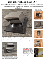
17-1/2 25-3/8 20-3/8 15 12-1/4 4-3/4 9-3/8 5-5/8
Millimeters
445 645 516 380 310 119 237 141
Table 2.1, Physical Dimensions
Figure 2.1, CSK-25 Dimensions
2.4 Appliance Dimensions

7
A
Fireplace insert
E
Log set (Refer to 8.5, #CXS-500 Log Set Installation, page 19)
B
Spring-loaded latch glass assembly
F
Refractory panels
C
Control board with burner cover
G
Fan kit
D
Co-linear air duct
Table 2.2, CSK-25 Part Assembly Overview
WARNING
Failure to position the parts in accordance with these diagrams, or failure to use only the specified approved parts with this appliance,
may result in property damage or personal injury.
A
D
F
B
G
C
Figure 2.2, CSK-25 Exploded View
2.5 Assembly Overview

8
WARNING
Figure 3.2, Mantel and Hearth Projections, provides the minimum clearances from the top surface of combustible flooring (carpeting,
tile, etc.). These clearances must be maintained.
Figure 3.2, Mantel and Hearth Projections
3 in.
(76 mm)
Combustible
Material
Figure 3.1, Appliance Clearance to Sidewall
3.0 CLEARANCES
This fireplace insert must be installed on a level surface capable of supporting fireplace and venting.
This fireplace insert is to be installed into a solid fuel masonry or factory built non-combustible fireplace that has been installed
in accordance with the national, provincial, state, and local building codes.
Due to high surface temperatures, the fireplace insert should be located out of traffic and away from furniture and draperies.
This fireplace insert may be installed in a bedroom.
Please be aware of the large amount of heat this fireplace insert will produce when determining a location.
3.1 Placement Clearance Requirements
3.2 Appliance Clearances

9
4.1 Existing Fireplace and Chimney Specifications
The existing fireplace and chimney must be clean, in good working order, and be constructed of non-combustible materials.
A gas line must be able to be installed to the insert. Refer to 6.0, Gas Line Connection, on page 14.
If the factory-built fireplace has no gas access hole(s) provided, an access hole of 1-1/2 in. (37.5 mm) or less may be drilled
through the lower sides or bottom of the firebox in a proper workmanship like manner. The access hole must be plugged with
non-combustible insulation after the gas supply line has been installed.
Provisions must be made to provide electrical power for appliance operation.
Any chimney clean-outs must fit properly.
NOTE
This insert is approved for installation in masonry and factory-built solid fuel burning fireplaces.
A
Height 17-5/8 in. 454 mm
B
Front Width 25-7/8 in. 657 mm
C
Depth 15-1/4 in. 387 mm
D
Back Width 20-5/8 in. 530 mm
Table 4.1, Minimum Opening Requirements
Figure 4.1, Existing Opening Guide
4.1.1 Existing Fireplace Opening Dimensions
4.0 EXISTING FIREPLACE REQUIREMENTS
4.1.2 Existing Chimney Specifications
The existing chimney must be comprised of one of the
following:
Factory built solid fuel chimney: 7 in. (178 mm) minimum
inside diameter
Masonry chimney: 6 in. x 8 in. (152 mm x 203 mm) minimum
inside diameter
Existing chimney height:
Minimum: 10 ft. (3.05 m)
Maximum: 35 ft. (10.67 m)
Refer to 4.1.3, Determine Length of Existing Chimney.
MEASUREMENT FROM FIREPLACE BASE TO TOP OF CHIMNEY
LESS 18-15/16” (478 MM) (AVERAGE HEIGHT OF INSERT)
-18-15/16” (478mm)
TOTAL CHIMNEY LENGTH REQUIRED
4.1.3 Determine Length of Existing Chimney
Min: 10 ft. (3.05m)
Max: 35 ft. (10.67m)
Figure 4.2 Min/Max Existing Chimney Length
1. Remove and discard existing chimney cap.
NOTE: It is helpful to have two people complete the next step to
determine the chimney height.
2. Position one person at the fireplace insert and another person at the top of the
chimney.
3. Measure from the fireplace insert base to the top of the chimney.
4. Subtract 18-15/16 in. (478 mm), the average height of the insert, from previous
measurement. This is the total length of the co-linear flexible aluminum required
for your installation.

10
5.0 INSTALLATION
5.1 Prepare Existing Fireplace
CAUTION
Trim panels or surrounds must not seal ventilation openings in existing fireplace that this appliance is installed in.
The refractory, glass doors, screen rails, screen mesh, and log grates may be removed from existing fireplace before installing
this gas fireplace insert.
Any smoke shelves, shields, and baffles may be removed if attached by mechanical fasteners. If necessary, remove firebrick
to obtain at least the minimum opening requirements.
The fireplace flue damper can be fully blocked, open, or removed for installation of this gas fireplace insert.
Clean the chimney and inside of the fireplace to prevent a creosote smell from entering the home.
Cutting of any sheet metal parts of the existing fireplace is prohibited, except the metal floor.
If the metal floor is removed, the insert must be placed directly on metal base of metal fireplace. Mechanically attach ‘THIS
UNIT HAS BEEN MODIFIED’ label at bottom of existing firebox so it will be visible if this gas fireplace insert is removed.
Run any necessary electrical wiring to insert. Refer to 7.0, Wiring Schematics, on page 15.
ATTENTION
Any removed parts must be capable of reinstallation if this insert is ever removed. Removal of rivets or screws is acceptable.
1. Remove air duct at top of insert, sliding backwards out of channel.
Refer to 5.6, Vent System Connection, for re-attachment of the air duct.
ATTENTION
All steps as outlined in 5.1, Prepare Existing Fireplace, must be completed before continuing with this installation.
Figure 5.1, Air Duct Removal
5.2 Fireplace Air Duct Removal
5.3 Combustion Air Venting Options
Full Connection Venting:
Combustion air intake pipe is ran entire chimney length and
connected to termination cap.
Stub Venting:
Combustion air intake pipe is extended a minimum of 4 ft.
(1.22 m) past damper opening into existing chimney. It is not
connected to termination cap.
Follow the instructions provided in this manual to the vent option required for installation, depending on which option used.

11
5.4.1 Stub Venting Assembly
1. Determine the length needed for the combustion air intake
pipe, measuring from the fireplace air duct to above to a
minimum length of 4 ft. (1.22 m) above the damper opening
in the existing chimney.
2. Remove the excess length of combustion air pipe (from the
end without a collar).
3. Extend the exhaust pipe equal to the total chimney length
required. Refer to 4.1.3, Determine Existing Chimney
Length, on page 9.
4. Place a bead of sealant around the inner edge at the end of
the exhaust pipe (without collar / red marking).
5. Slide the exhaust pipe onto corresponding labeled collar
(B) on the termination cap (E).
6. Secure the exhaust pipe to the termination cap (E) with the
provided (3) self-tapping screws. Apply additional sealant
around joint to ensure a proper seal (C
1
).
7. Run vent system through existing chimney. Refer to 5.5.1,
Run Vent - Stub Venting, on page 12.
5.4.2 Full Connection Venting Assembly
1. Carefully extend the exhaust and combustion air intake
pipes to the total chimney length required. Refer to 4.1.3,
Determine Existing Chimney Length, on page 9.
2. Slide the combustion air intake pipe (the end without a
collar) over the intake termination cap collar (A).
3. Secure the combustion air intake pipe to the termination
cap (E) with the provided (3) self-tapping screws (D).
4. Place a bead of sealant around the inner edge at the end of
the exhaust pipe (without collar / red marking).
5. Slide the exhaust pipe onto corresponding labeled collar
(B) on the termination cap (E).
6. Secure the exhaust pipe to the termination cap (E) with the
provided (3) self-tapping screws. Apply additional sealant
around joint to ensure a proper seal (C
1
).
7. Run vent system. Refer to 5.5.2, Run Vent - Full
Connection Venting, on page 12.
IMPORTANT
Proper operation of this insert requires exhaust and combustion air pipes be connected to the correct collars on both the termination kit
and the fireplace insert air duct.
5.4 Kozy Heat #816-CL Co-Linear Vent System
LEGEND
A
Intake Collar - extends through bottom plate
B
Exhaust Collar - extends through middle divider plate
C
1 -
C
2
Sealant
D
Self-Tapping Screws - (3) total (2 shown)
E
Termination Cap
EXHAUST PIPE IDENTIFICATION: RED MARKING
Figure 5.2, #816-CLTermination Cap (your component may look different than one shown)
c
1
c
2
E
IMPORTANT
The exhaust collar on the fireplace insert air duct is on the on the right side. Install the #816-CL termination cap (E) with exhaust collar
on the right side.

12
5.5.1 Run Vent - Stub Venting
1. Guide the rope (if used) and the exhaust pipe down the
existing chimney. See Figure 5.3, Chimney Vent Run.
2. Secure the chimney termination cap to the existing
chimney.
Approved Vent Systems: Apply a liberal bead of
sealant (provided) around the top of existing chimney. Set
termination cap into position as instructed in installation
manual included with chosen vent system.
Kozy Heat #816-CL: Secure termination cap to
existing chimney with 2 in. (50 mm) self tapping screws
and anchor straps (provided) through the pilot holes,
located on the sides of the termination cap.
3. From inside the existing fireplace, insert a minimum of 4 ft.
(1.22m) of combustion air pipe (end without collar) past the
damper opening and into the existing fireplace firebox. See
Figure 5.4, Stub Venting.
Hussong Mfg. strongly suggests placing non-faced
fiberglass insulation between the vent pipes and the
existing chimney to prevent heat loss up the chimney,
being careful not to the block the combustion air intake
pipe end.
5.5.2 Run Vent - Full Connection Venting
Hussong Mfg. strongly suggests wrapping first 3 ft. (914
mm) of vent system below termination cap with non-faced
fiberglass insulation (secure with wire) before running it
through existing chimney. This will prevent cold air from
coming down existing chimney.
1. Guide ropes (if used) and the flexible pipes down the
existing chimney. See Figure 5.3, Chimney Vent Run.
2. Secure the chimney termination cap to the existing
chimney.
Approved Vent Systems: Apply a liberal bead of
sealant (provided) around top of existing chimney. Set
termination cap into position as instructed in installation
manual included with chosen vent system.
Kozy Heat #816-CL: Secure termination cap to
existing chimney with 2 in. (50 mm) self tapping screws
and anchor straps (provided) through the pilot holes,
located on the sides of the termination cap.
3. From inside the existing fireplace, carefully pull ropes (if
used) or the flexible pipes down until both the exhaust pipe
and the combustion air intake are into the existing fireplace
firebox.
NOTE
If offsets are present in existing chimney, place a weighted rope around the pipe ends to guide them through chimney.
DO NOT ATTEMPT TO TIE ONE ROPE AROUND BOTH PIPES.
Minimum 4 ft. (1.22m)
length of 3” (76 mm)
combustion air flex pipe
above register opening
DO NOT block pipe
end with insulation
or any other
sealing materials
3" (76 mm) exhaust
flex pipe must be
connected to collar
on fireplace insert
and termination cap
Seal area around vent
pipes with non-faced
fiberglass insulation
Figure 5.4, Stub Venting
Figure 5.3, Chimney Vent Run
5.5 Run Vent System Through Existing Chimney

13
1. Place previously removed air duct (5.2, Air Duct Removal, page 10) into existing fireplace opening. See Figure 5.5a, Air Duct in
Existing Fireplace.
2. Apply a bead of sealant (provided) around exhaust pipe collar (red marking), then slide the exhaust pipe onto collar marked
‘Exhaust’ on air duct.
3. Secure the exhaust pipe to the collar on the air duct with (3) 1/2 in. (13 mm) self-tapping screws, provided. Apply additional
sealant around joint to ensure an air tight seal. See Figure 5.5b, Flexible Pipes Attached to Air Duct.
4. Apply a liberal bead of sealant (provided) around the collar on the air duct. Slide combustion intake pipe over collar.
5. Secure the combustion intake pipe to the collar on the air duct with (3) 1/2 in. (13 mm) self-tapping screws, provided. Apply
additional sealant around joint to ensure an air tight seal.
6. Slide the insert into fireplace opening far enough to align the air duct with the channels at top of insert. See Figure 5.5c,
Aligned Fireplace Insert.
1. Insert air duct pull handle through the access slot the at top of insert, placing hook through hole in pull rod. See Figure 5.6a,
Pull Rod Handle and Access Slot.
2. Simultaneously pull the air duct forward and push the insert backward into the fireplace opening until the air duct is seated and
the insert is properly positioned.
3. Use the slots at top of fireplace to secure the air duct to the fireplace insert with (2) 1/2 in. (13 mm) sheet metal screws
(included in components packet). See Figure 5.6b, Seated Air Duct.
4. Use the pull rod handle to slide pull rod back to its starting position. Remove pull rod handle. See Figure 5.6b.
If necessary, level the insert by threading leveling bolts (included in components packet) into nuts at the bottom of the insert - 2
each side.
5.6.2 Secure Air Duct to Fireplace Insert
Pull rod
handle
Figure 5.6a, Pull Rod Handle and Access Slot
(shown without venting attached for clarity purposes only)
Figure 5.5c,
Aligned Fireplace Insert
Figure 5.5a,
Air Duct in Existing Fireplace
Air Duct
5.6 Vent System Connection (applies to both venting options)
5.6.1 Secure Vent System to Air Duct
Figure 5.5b,
Flexible Pipes Attached to Air Duct
Sealant
Sheet metal
screws (3 total)
Pull rod
Secure with (2) screws through slots
Figure 5.6b, Seated Air Duct
(shown without venting attached for clarity purposes only)

14
6.0 GAS LINE CONNECTION
6.2 Gas Line Installation
Table 6.1, Inlet Gas Pressures
Fuel Minimum Inlet Gas Pressure Maximum Inlet Gas Pressure
Natural Gas
5” WC (1.25 kPa) (7” WC [1.74 kPa] recommended) 10.5” WC (2.62 kPa)
LP Gas
12” WC (2.99 kPa) (recommended) 13” WC (3.24 kPa)
6.1 Gas Conversion (sold separately)
This fireplace is manufactured for use with Natural Gas. Follow the instructions included with the conversion kit if converting to
LP gas.
ATTENTION
The conversion shall be carried out in accordance with the requirements of the provincial authorities having jurisdiction and in
accordance with the requirements of the ANSI Z223.1 installation code.
CAUTION
Installation of the gas line must only be done by a qualified person in accordance with local building codes, if any. If not, follow ANSI
223.1. Commonwealth of Massachusetts installations must be done by a licensed plumber or gas fitter.
A listed (and Commonwealth of Massachusetts approved) 1/2 in. (13 mm) tee handle manual shut-off valve and flexible gas
connector are to be connected to the 1/2 in. (13 mm) control valve inlet. If substituting for these components, please consult
local codes for compliance.
If installing this insert into minimum opening dimensions, the gas line may need to be run after placement due to space
limitations. Refer to 4.1.1, Existing Fireplace Opening Specifications, on page 9.
This fireplace is equipped with a 3/8” (10 mm) x 18” (457 mm) long flexible gas connector and manual shut-off valve.
Run gas line into fireplace, preferably through left or right gas line holes provided. The gas line should be run to the point of
connection where the shut-off valve and flexible gas line will connect.
Do not run gas line in a manner that would obstruct fan operation.
For high altitude installations, consult the local gas distributor or the authority having jurisdiction for proper rating methods.
NOTE
The appliance and its individual shutoff valve must be disconnected from the gas supply piping system during any pressure testing of
that system at pressures in excess of ½ psi (3.5 kPa). For test pressures equal to or less than ½ psi (3.5 kPa), the appliance must be
isolated from the gas supply piping system by closing its individual manual shut-off valve.
Leak test all gas line joints and the gas control valve prior to lighting the appliance.

15
ATTENTION
Electrical wiring must be installed by a licensed electrician.
IFC Control Module
1.5 V type AA
1.5 V type AA
1.5 V type AA
1.5 V type AA
Flame
Sensor
SW1 Button (red)
Igniter
Pilot
Pilot
Burner
885 Proflame
Battery Pack
Main ON /OFF
Switch
Variable Speed Fan
Appliance
Ground Star
Variable Lights
Male End
Figure 7.1, IFC Control Module Wiring
7.0 WIRING SCHEMATICS
IMPORTANT
This system requires 120V of electricity / batteries to operate.

16
8.0 FIREPLACE INSERT SETUP
8.2 Safety Barriers
WARNING
Do not operate this fireplace with the glass removed, cracked, or broken. Replacement of the glass frame assembly, #CXS-057T, should
be done by a licensed or qualified service person.
Do not remove the glass frame assembly when hot.
1. Align the slots on top of the glass frame assembly over the tabs at the top of the firebox while lowering the bottom of the glass
frame assembly into position. Refer to Figure 8.2, Glass Frame Assembly Installation.
2. Pull the spring-loaded latches out and up to secure the bottom of glass frame to the bottom of the fireplace.
1. Locate (2) spring-loaded latches securing the glass frame assembly at the bottom of the firebox. Refer to Figure 8.1, Glass
Frame Assembly Removal.
2. Pull the spring-loaded latches out and down to release the bottom of the glass frame assembly.
3. Lift glass frame assembly up and off of the (2) tabs located at the top of the firebox.
Figure 8.2, Glass Frame Assembly Installation
Figure 8.1, Glass Frame Assembly Removal
8.1 Glass Frame Assembly
8.1.1 Remove Glass Frame Assembly
8.1.2 Install Glass Frame Assembly
R.03
1. Locate the four (4) openings located on the left and right sides of the shroud (2 each side).
2. Align the screen front’s mounting brackets (located on the back) with the openings on the shroud.
3. Lower the screen front into the shroud openings, securing the screen front into place.
4. To remove safety screen: lift the screen up and out of the shroud openings.
Refer to Figure 8.3, Safety Barrier Dimensions, on page 17.
NOTE
Safety barriers #CXS-PFS, #CXSA-PSF, #CXSA-MSF, and #CXS-RSF mount on the three shrouds offered by Kozy Heat Fireplaces.

17
Figure 8.3, Safety Barrier Dimensions

18
1. Align the slots in the upper hood with the corresponding slots in the mounting flange located at the top of the insert.
2. Push back the upper hood into position. Refer to Figure 8.4, Upper Hood Installation
Upper hood
Lower louver
1. Align the slots in the lower louver to the corresponding slots in the mounting brackets located at the bottom of the insert.
2. Set the lower louver down into position. Refer to Figure 8.5, Lower Louver Installation.
Figure 8.5, Lower Louver Installation
Figure 8.4, Upper Hood Installation
8.4 Upper Hood and Lower Louver
8.4.1 Upper Hood Installation
8.4.2 Lower Louver Installation
1. Remove the safety barrier and glass assembly from fireplace.
2. Lay shroud sections face down on a protective surface to assemble.
3. Attach leg sections to top section by aligning holes (2 ea. side) in top section with holes in leg sections.
4. Secure with sheet metal screws (2 ea. side).
OPTIONAL: Attach shroud extensions by aligning slots in shroud with the desired whole in shroud extensions.
Secure with sheet metal screws.
5. Align mounting holes in leg sections to corresponding mounting nuts on the sides of the insert opening.
6. Secure with (4) truss head screws.
7. Reinstall glass frame assembly.
8. Install upper hood and lower louver.
9. Reinstall safety barrier.
NOTE
If installing a Full Door Shroud, follow instructions included with the component.
(3) ZC Shroud -
top, left, & right leg
(2) shroud extensions
(8) sheet metal screws
(4) truss head screws
You will also need the upper hood and lower louver (included with the fireplace).
8.3 ZC Shroud Assembly and Installation
8.3.1 Shroud Assembly Components
8.3.2 Assembly and Installation Instructions

19
CS1
CS4
CS2
CS3
Figure 8.6a, Log Set Installation
8.5 #CXS-500 Log Set Installation
NOTE
Log numbers are located on the bottom of each log. Refer to the Figures 8.6a and 8.6b for proper installation.
ATTENTION
If converting to LP (propane) gas, do so now before installing any media kit. Follow instructions included with the conversion kit (sold
separately).
1. Position CS1 log over pilot shield as shown in Figure 8.6a.
2. Align the holes in bottom of base logs CS2, CS3, and CS4 to mounting pins on the burner. Push logs down onto pins to seat.
3. Align CS5, CS6, CS7 and CS8 logs with the notches in the base logs (CS2-CS4) as shown in Figure 8.6b.
4. Randomly place “Klinkers” in the area as shown in Figure 8.6b. Do not place directly on burner ports. Use a steel or stiff bristle
nylon brush to distribute Rock Wool Embers onto logs and burner.
CAUTION
Do not place logs directly over burner port holes. Improper log placement may affect flame appearance and cause excessive soot to
build up on logs and glass.
Figure 8.6b, Log Set and Klinker / Rock Wool Ember Installation
CS6
CS7
CS8
CS5
Randomly place Klinkers in this area.
/