730865-100 Rev. L
- 3 -
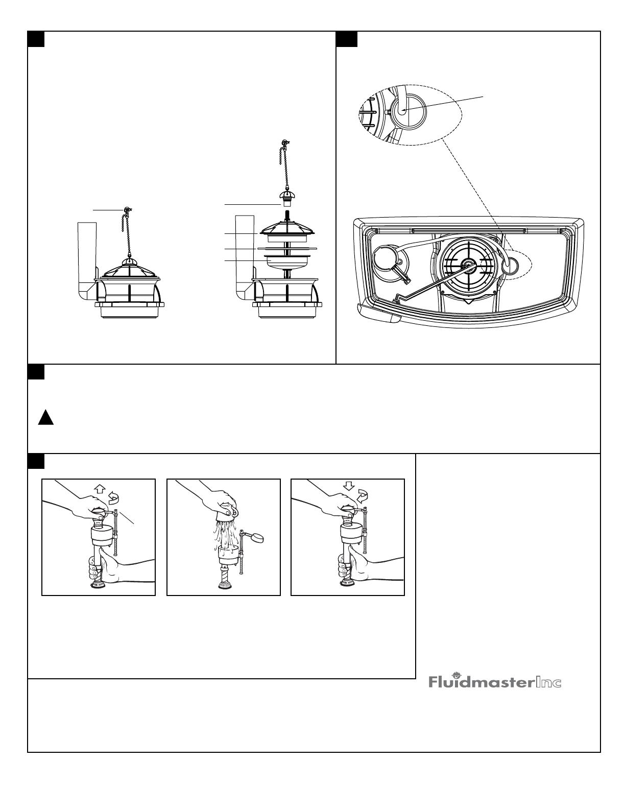
•
Make sure water supply is off.
Remove valve TOP by lifting
arm and rotating top and arm
1/8 turn counterclockwise,
pressing down slightly on cap.
IMPORTANT: Always clear
sand and rust from system.
• While holding a
container over the
uncapped VALVE to
prevent splashing, turn
water supply on and
off a few times. Leave
water supply off.
• Replace TOP by engaging
lugs and rotating 1/8 turn
clockwise. MAKE CERTAIN
TIP IS TURNED TO THE
LOCKED POSITION. VALVE
MAY NOT TURN ON IF TOP
IS NOT FULLY TURNED TO
THE LOCKED POSITION.
For troubleshooting information please contact:
TROUBLESHOOTING
IF FILL VALVE SHUTS OFF BUT CONTINUES TO
LEAK SLOWLY, repeat Step 13.
IF FILL VALVE TURNS OFF AND ON DURING
PERIODS OF NON-USE, it is a signal you are
wasting water because:
• The end of the refill tube is inserted into overflow
pipe, below water level in tank. Attach refill tube to
overflow pipe using "S" clip provided.
• The flush valve is leaking because it's worn, dirty
or misaligned.
IF FILL VALVE WON'T TURN ON OR SHUT OFF
or REFILL OF TANK WATER IS SLOW after
valve has been in use for some time, Fluidmaster
Model 242 Replacement Seal may be needed.
Go to our website at www.fluidmaster.com for
more solutions to toilet problems.
© 2001 Fluidmaster, Inc.
® Registered trademark of Fluidmaster, Inc.
Always use quality Fluidmaster repair parts when maintaining your Fluidmaster products. Fluidmaster
shall not be responsible or liable for any damages caused by products used with Fluidmaster valves
that were not manufactured by Fluidmaster, Inc.
30800 Rancho Viejo Road
San Juan Capistrano, CA 92675
(949) 728-2000 (800) 631-2011
www.fluidmaster.com
CARE AND CLEANING
American Standard shall not be responsible or liable for any damage caused by the use of in-tank cleaners.
Do not use in-tank cleaners. These products can seriously damage fittings in the tank.
This damage can cause leakage and property damage.
WARNING:
!
When cleaning your toilet, wash it with mild, soapy water, rinse thoroughly with clear water and dry with a soft cloth.
TROUBLE SHOOTING FLUSH VALVE SEAL LEAKS:
Lift piston up by pulling up on the lift chain, inspect seal for visible
distortion and presence of debris on sealing surface with finger.
SEAL REPLACEMENT:
1. Turn off water supply and flush toilet to empty tank.
2. Disconnect Chain from Trip Lever by removing Hair Pin Cotter
and Clevis Pin.
3. Partially lift and support piston bottom with one hand.
4. Remove thumbscrew by turning counter-clockwise.
5. Remove piston top and gasket.
6. Replace gasket with new gasket.
7. Reverse procedure, turn thumbscrew until 2 clicks are felt.
11 11a
12
13
LIFT ARM
FIRST
REFILL TUBE REPLACEMENT:
NOTE: DO NOT ADD ANY FOREIGN MATERIALS TO THE SEALING SURFACE.
THUMBSCREW
PISTON TOP
PISTON BOTTOM
GASKET
HAIR PIN
COTTER
Locate bottom portion of
hose clip to vent tube at
location as shown.
F


