Cisco UCS-CPU-E5-2470 Datasheet
- Category
- Processors
- Type
- Datasheet

CISCO SYSTEMS PUBLICATION HISTORY
170 W
EST TASMAN DR.
S
AN JOSE, CA, 95134 REV A.2 JULY 5, 2012
WWW.CISCO.COM
Spec Sheet
Cisco UCS B22 M3
Blade Server

Cisco UCS B22 M3 Blade Server
2
CONTENTS
OVERVIEW . . . . . . . . . . . . . . . . . . . . . . . . . . . . . . . . . . . . . . . . . . . . . . . 3
DETAILED VIEWS . . . . . . . . . . . . . . . . . . . . . . . . . . . . . . . . . . . . . . . . . . . 4
Blade Server Front View . . . . . . . . . . . . . . . . . . . . . . . . . . . . . . . . . . . . . . . . . . . . . . .4
BASE SERVER STANDARD CAPABILITIES and FEATURES . . . . . . . . . . . . . . . . . 5
CONFIGURING the SERVER . . . . . . . . . . . . . . . . . . . . . . . . . . . . . . . . . . . . 7
STEP 1 VERIFY SERVER SKU . . . . . . . . . . . . . . . . . . . . . . . . . . . . . . . . . . . . . . . . . . . .8
STEP 2 CHOOSE CPU(S) . . . . . . . . . . . . . . . . . . . . . . . . . . . . . . . . . . . . . . . . . . . . . .9
STEP 3 CHOOSE MEMORY . . . . . . . . . . . . . . . . . . . . . . . . . . . . . . . . . . . . . . . . . . . . 11
STEP 4 CHOOSE HARD DISK DRIVES or SOLID STATE DRIVES (OPTIONAL) . . . . . . . . . . . . . . 15
STEP 5 CHOOSE MODULAR LOM and/or PCIe MEZZANINE CARDS . . . . . . . . . . . . . . . . . . . 17
STEP 6 ORDER A TRUSTED PLATFORM MODULE . . . . . . . . . . . . . . . . . . . . . . . . . . . . . . 20
STEP 7 ORDER CISCO FLEXIBLE FLASH SECURE DIGITAL CARDS . . . . . . . . . . . . . . . . . . . . 21
STEP 8 ORDER OPTIONAL INTERNAL USB 2.0 DRIVE . . . . . . . . . . . . . . . . . . . . . . . . . . . 22
STEP 9 CHOOSE OPERATING SYSTEM . . . . . . . . . . . . . . . . . . . . . . . . . . . . . . . . . . . . . 23
STEP 10 CHOOSE OPERATING SYSTEM MEDIA KIT . . . . . . . . . . . . . . . . . . . . . . . . . . . . . 26
STEP 11 CHOOSE OPTIONAL VALUE-ADDED SOFTWARE . . . . . . . . . . . . . . . . . . . . . . . . . 27
STEP 12 CHOOSE SERVICE and SUPPORT LEVEL . . . . . . . . . . . . . . . . . . . . . . . . . . . . . . 28
ORDER OPTIONAL KVM LOCAL I/O CABLE* . . . . . . . . . . . . . . . . . . . . . . . . . . . . . . . . . . .32
SUPPLEMENTAL MATERIAL . . . . . . . . . . . . . . . . . . . . . . . . . . . . . . . . . . . 33
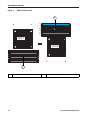
System Board . . . . . . . . . . . . . . . . . . . . . . . . . . . . . . . . . . . . . . . . . . . . . . . . . . . . .33
DIMM and CPU Layout . . . . . . . . . . . . . . . . . . . . . . . . . . . . . . . . . . . . . . . . . . . . . . . .34
System Speed as a Function of DIMMs Per Channel (for a 3 DIMM Per Channel System) . 35
Network Connectivity . . . . . . . . . . . . . . . . . . . . . . . . . . . . . . . . . . . . . . . . . . . . . . . .36
Modular LOM Card . . . . . . . . . . . . . . . . . . . . . . . . . . . . . . . . . . . . . . . . . . . . . . 37
Mezzanine Cards . . . . . . . . . . . . . . . . . . . . . . . . . . . . . . . . . . . . . . . . . . . . . . . 38
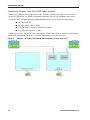
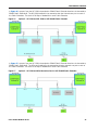
Connectivity using the Cisco UCS 2208XP Fabric Extender . . . . . . . . . . . . . . . . . . . . 39
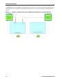
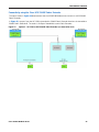
Connectivity using the Cisco UCS 2204XP Fabric Extender . . . . . . . . . . . . . . . . . . . . 42
Connectivity using the Cisco UCS 2104XP Fabric Extender . . . . . . . . . . . . . . . . . . . . 45
TECHNICAL SPECIFICATIONS . . . . . . . . . . . . . . . . . . . . . . . . . . . . . . . . . . 46
Dimensions and Weight . . . . . . . . . . . . . . . . . . . . . . . . . . . . . . . . . . . . . . . . . . . . . . .46
Power Specifications . . . . . . . . . . . . . . . . . . . . . . . . . . . . . . . . . . . . . . . . . . . . . . . .46

Cisco UCS B22 M3 Blade Server
OVERVIEW
2
OVERVIEW
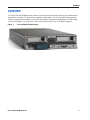
The Cisco® UCS B22 M3 Blade Server delivers a balanced price/performance feature set to address quick
deployment of scalable IT infrastructure and Web 2.0 applications. The Cisco UCS B22 M3 harnesses the
power of the latest Intel® Xeon® processor E5-2400 product family with expandability to 192 GB of RAM
(using 16 GB DIMMs), 2 hot-plug drives, and 2 PCIe mezzanine slots for up to 80 Gbps throughput.
Figure 1 Cisco UCS B22 M3 Blade Server

Cisco UCS B22 M3 Blade Server
3
DETAILED VIEWS
DETAILED VIEWS
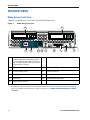
Blade Server Front View
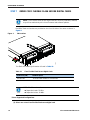
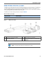
Figure 2 is a detailed front view of the Cisco UCS B22 M3 Blade Server.
Figure 2 Blade Server Front View
1 Asset pull handle
(a blank asset tag is provided on which
you can add your own label or sticker or
you can use a marker to write your asset
information on the tag)
7 Network link status LED
2 Blade ejector handle 8 Blade health LED
3 Ejector captive screw 9
Console connector
1
Notes
1. For information about the KVM local I/O cable that plugs into the console connector (a cable is included with
every Cisco UCS 5100 Series blade server chassis accessory kit), see ORDER OPTIONAL KVM LOCAL I/O CABLE*
on page 30.
4 Drive bay 1 10 Reset button access
5 Drive bay 2 11 Beaconing LED and button
6 Power button and LED - -
UCS B22 M3
1 2 3
6
7
8
9
10
11
4 5
332661

Cisco UCS B22 M3 Blade Server
BASE SERVER STANDARD CAPABILITIES and FEATURES
4
BASE SERVER STANDARD CAPABILITIES and FEATURES
Table 1 lists the capabilities and features of the base server. Details about how to configure the server for
a particular feature or capability (for example, number of processors, disk drives, or amount of memory)
are provided in
CONFIGURING the SERVER on page 6.
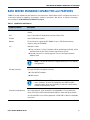
Table 1 Capabilities and Features
Capability/Feature Description
Chassis The UCS B22 M3 Blade Server mounts in a Cisco UCS 5100 series blade server
chassis
CPU One or two Intel® E5-2400 series processor family CPUs
Chipset Intel® C600 series chipset
Memory 12 total slots for registered ECC DIMMs for up to 192 GB total memory
capacity (using 16 GB DIMMs)
I/O Mezzanine cards:
■ First connector for Cisco’s modular LAN on motherboard (mLOM), which
provides Ethernet and Fibre Channel over Ethernet (FCoE)
■ Second connector for various types of Cisco or third-party network
adapter cards
Storage controller LSI Logic SAS 2002 integrated controller
■ 6 Gbs SAS/SATA support
■ RAID 0 and 1
Internal storage devices Up to two optional, front-accessible, hot-swappable 2.5-inch small form
factor (SFF) SAS or SATA solid-state disks (SSDs) or hard disk drives (HDDs).
An internal USB 2.0 port is also supported. A 4 GB USB 2.0 device is available
from Cisco.
NOTE: The second connector is supported only for 2-CPU system
configurations.
NOTE: The integrated RAID controller does not implement a write
cache. However, servers that implement two HDDs and RAID
controllers with cache lack the ability to match the performance
of RAID’ed SSDs without cache.

Cisco UCS B22 M3 Blade Server
5
BASE SERVER STANDARD CAPABILITIES and FEATURES
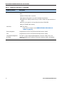
Video The Emulex Pilot 3 Integrated Baseboard Management Controller provides
video:
■ Matrox G200e video controller
■ Integrated 2D graphics core with hardware acceleration
■ Supports all display resolutions up to 1920 x 1200 x 16 bpp resolution at
60 Hz
■ 24-bit color depth for all resolutions less than 1600x1200
■ Up to 256 MB video memory
Interfaces ■ Front panel
• One console connector (see ORDER OPTIONAL KVM LOCAL I/O
CABLE* on page 30)
Power subsystem Integrated in the Cisco UCS 5100 series blade server chassis
Fans Integrated in the Cisco UCS 5100 series blade server chassis
Integrated management
processor
The built-in Cisco Integrated Management Controller (CIMC) GUI or CLI
interface enables you to monitor the server inventory, health, and system
event logs.
Table 1 Capabilities and Features (continued)
Capability/Feature Description

Cisco UCS B22 M3 Blade Server
CONFIGURING the SERVER
6
CONFIGURING the SERVER
Follow these steps to configure the Cisco UCS B22 M3 Blade Server:
■ STEP 1 VERIFY SERVER SKU, page 7
■ STEP 2 CHOOSE CPU(S), page 8
■ STEP 3 CHOOSE MEMORY, page 10
■ STEP 4 CHOOSE HARD DISK DRIVES or SOLID STATE DRIVES (OPTIONAL), page 13
■ STEP 5 CHOOSE MODULAR LOM and/or PCIe MEZZANINE CARDS, page 15
■ STEP 6 ORDER A TRUSTED PLATFORM MODULE, page 18
■ STEP 7 ORDER CISCO FLEXIBLE FLASH SECURE DIGITAL CARDS, page 19
■ STEP 8 ORDER OPTIONAL INTERNAL USB 2.0 DRIVE, page 20
■ STEP 9 CHOOSE OPERATING SYSTEM, page 21
■ STEP 10 CHOOSE OPERATING SYSTEM MEDIA KIT, page 24
■ STEP 11 CHOOSE OPTIONAL VALUE-ADDED SOFTWARE, page 25
■ STEP 12 CHOOSE SERVICE and SUPPORT LEVEL, page 26

Cisco UCS B22 M3 Blade Server
7
CONFIGURING the SERVER
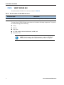
STEP 1 VERIFY SERVER SKU
Verify the product ID (PID) of the server as shown in Table 2.
The base Cisco UCS B22 M3 blade server does not include the following components. They are to
be selected during product ordering:
■ CPU(s)
■ Memory
■ Disk drives
■ VIC 1240 modular LAN-on-Motherboard (mLOM) card
■ Mezzanine card
Table 2 PID of the Base UCS B22 M3 Blade Server
Product ID (PID) Description
UCSB-B22-M3 UCS B22 M3 Blade Server without CPU, memory, HDD, or mLOM/mezzanine cards
NOTE: Use the steps on the following pages to order the UCS B22 M3
server with the configurable components that you want configured.

Cisco UCS B22 M3 Blade Server
CONFIGURING the SERVER
8
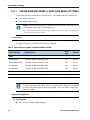
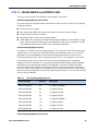
STEP 2 CHOOSE CPU(S)
The standard CPU features are:
■ Intel Xeon processor E5-2400 series family CPUs
■ Intel C600 series chipset
■ Cache sizes of 10, 15, or 20 MB
Select CPUs
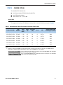
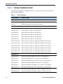
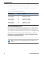
The supported Intel Xeon E5-2400 series family CPUs on the UCS B22 M3 are listed in Table 3.
Table 3 Supported Intel CPUs: E5-2400 Series Processor Family CPUs
Product ID (PID)
Intel
Number
Clock
Freq
(GHz)
Power
(W)
Cache Size
(MB)
Cores QPI
Highest DDR3 DIMM
Clock Support (MHz)
1
Notes
1. If higher or lower speed DIMMs are selected than what is shown in the table for a given CPU, the DIMMs will be
clocked at the lowest common denominator of CPU clock and DIMM clock. For example:
Selecting lower-speed DIMMs
: If you use an E4-2470 CPU (which can support up to 1600-MHz DIMMs) with 1333-MHz
DIMMs, the DIMMs will be clocked at the lower speed of 1333 MHz.
Selecting higher-speed DIMMs:
If you use 1600-MHz DIMMs with an E5-2420 CPU (which can support up to 1333-MHz
DIMMs), the DIMMS will be clocked at the lower speed of 1333 MHz.
UCS-CPU-E5-2470 E5-2470 2.30 95 20 8 8 GT/s 1600
UCS-CPU-E5-2450 E5-2450 2.10 95 20 8 8 GT/s 1600
UCS-CPU-E5-2440 E5-2440 2.40 95 15 6 7.2 GT/s 1333
UCS-CPU-E5-2430L E5-2430L 2.00 60 15 6 6.4 GT/s 1333
UCS-CPU-E5-2420 E5-2420 1.90 95 15 6 7.2 GT/s 1333
UCS-CPU-E5-2403 E5-2403 1.80 80 10 4 6.4 GT/s 1066

Cisco UCS B22 M3 Blade Server
9
CONFIGURING the SERVER
Supported Configurations
(1) 1-CPU Configuration
■ Choose one CPU from any one of the rows of Table 3 on page 8.
(2) Two-CPU Configuration
■ Choose two identical CPUs from any one of the rows of Table 3 on page 8.
Caveats
■ The VIC 1240 card is supported for 1- or 2-CPU configurations.
■ Mezzanine cards are supported only for 2-CPU configurations.

Cisco UCS B22 M3 Blade Server
CONFIGURING the SERVER
10
STEP 3 CHOOSE MEMORY
The standard memory features are:
■ DIMMs
— Clock speed: 1600 MHz
— Ranks per DIMM: 1 or 2
— Operational voltage: dual (1.5 or 1.35 V)
—Registered
■ DDR3 ECC registered DIMMs (RDIMMs)
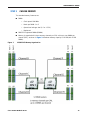
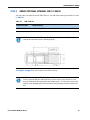
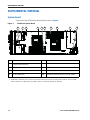
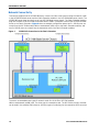
■ Memory is organized with three memory channels per CPU, with up to two DIMMs per
channel (DPC), as shown in
Figure 3. Maximum memory capacity is 192 GB (with 16 GB
DIMMs).
Figure 3 UCS B22 M3 Memory Organization

Cisco UCS B22 M3 Blade Server
11
CONFIGURING the SERVER
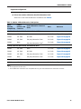
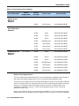
Choose DIMMs and Memory Mirroring
Select the memory configuration and whether or not you want the memory mirroring option.
The supported memory DIMMs and the mirroring option are listed in
Table 4.
The supported memory DIMMs in the UCS B22 M3 are listed in Table 4.
NOTE: When memory mirroring is enabled, the memory subsystem simultaneously
writes identical data to two adjacent channels. If a memory read from one of the
channels returns incorrect data due to an uncorrectable memory error, the system
automatically retrieves the data from the other channel. A transient or soft error in
one channel does not affect the mirrored data, and operation continues unless there
is a simultaneous error in exactly the same location on a DIMM and its mirrored
DIMM. Memory mirroring reduces the amount of memory available to the operating
system by 50% because only one of the two populated channels provides data.
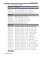
Table 4 Supported DDR3 DIMMs and Memory Mirroring Option
Product ID (PID) PID Description Voltage
Ranks
/DIMM
DIMM Options
UCS-MR-1X162RY-A 16GB DDR3-1600-MHz RDIMM/PC3-12800/2R/x4/1.35v/35nm 1.35/1.5 V 2
UCS-MR-1X082RY-A 8GB DDR3-1600-MHz RDIMM/PC3-12800/2R/x4/1.35v/35nm 1.35/1.5 V 2
UCS-MR-1X041RY-A 4GB DDR3-1600-MHz RDIMM/PC3-12800/1R/x4/1.35v/35nm 1.35/1.5 V 1
Memory Mirroring Option
N01-MMIRROR Memory mirroring option

Cisco UCS B22 M3 Blade Server
CONFIGURING the SERVER
12
Supported Configurations
(1) Without memory mirroring:
■ Select from 1 to 6 DIMMs per CPU (note that there are 6 DIMM slots per CPU)
(2) With memory mirroring:
■ Select 2 or 4 DIMMs per CPU. The DIMMs must be identical across channels for the same
banks.The DIMMs will be placed by the factory as shown in
Table 5:
■ Select the memory mirroring option (N01-MMIRROR) as shown in Table 4 on page 11.
Caveats
■ For 2-CPU configurations, DIMMs must be even across the server (2, 4, 6 up to 12). For
example, you can select four 8 GB DIMMs and six 16 GB DIMMs.
■ Memory mirroring reduces the amount of available memory by 50% (quantity of DIMMs must
be even for mirroring).
■ By default, all DIMMs run at 1.35 V, which yields 1333-MHz memory speeds. To run the
memory DIMMS at 1600 MHz, you need to go into the BIOS or set the policy with UCSM
(service profile) to run in Performance Mode. This forces the DIMMs to operate at 1.5 V and
yields 1600-MHz speeds provided:
— The DIMMs are 1600-MHz devices
— The CPUs chosen support 1600-MHz operation
For more information regarding memory, see DIMM and CPU Layout on page 32 and
DIMM Population on page 34.
Table 5 DIMM Placement With Memory Mirroring
Number of
DIMMs per
CPU
DIMM Placement in Channels (with memory mirroring implemented).
Note that Channels B and F are not used for memory mirroring
CPU 1 CPU 2
2 1 DIMM in Channel C (C0),
1 DIMM in Channel D (D0)
1 DIMM in Channel G (G0),
1 DIMM in Channel H (H0)
4 2 DIMMs in Channel C (C0, C1),
2 DIMMs in Channel D (D0, D1)
2 DIMMs in Channel G (G0, G1),
2 DIMMs in Channel H (H0. H1)
NOTE: System performance is optimized when the DIMM type and quantity are equal
for both CPUs, and when all channels are filled equally across the CPUs in the server.

Cisco UCS B22 M3 Blade Server
13
CONFIGURING the SERVER
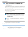
STEP 4 CHOOSE HARD DISK DRIVES or SOLID STATE DRIVES (OPTIONAL)
The UCS B22 M3 can be ordered with or without drives. The standard disk drive features are:
■ 2.5-inch small form factor
■ Hot-pluggable sled mounted
Choose Drives
The supported drives in the UCS B22 M3 are listed in Table 6.
Supported Configurations
(1) 1-Drive System
■ Select one of the drives listed in Table 6.
NOTE: The UCS B22 M3 blade server meets the external storage target and switch
certifications as described in the following link:
http://www.cisco.com/en/US/docs/switches/datacenter/mds9000/interoperability
/matrix/Matrix8.html#wp323852
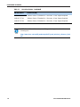
Table 6 Supported Hot-Pluggable Sled-Mounted HDDs and SSDs
Product ID (PID) PID Description
Drive
Type
Capacity
HDDs
A03-D600GA2 600 GB 6 Gb SAS 10K RPM SFF HDD SAS 600 GB
UCS-HDD300GI2F105 300 GB 6 Gb SAS 15K RPM SFF HDD SAS 300 GB
A03-D300GA2 300 GB 6 Gb SAS 10K RPM SFF HDD SAS 300 GB
A03-D146GC2 146 GB 6 Gb SAS 15K RPM SFF HDD SAS 146 GB
SSDs
UCS-SD100G0KA2-E 100 GB Std Height 15mm SATA SSD SATA 100 GB
NOTE: The integrated LSI 2002 MegaRAID controller supports hard disk drives (HDDs)
or solid state drives (SSDs). Write cache is not implemented. SSDs are recommended
for applications requiring high-speed local storage, which is an order of magnitude
faster than HDDs.


Cisco UCS B22 M3 Blade Server
15
CONFIGURING the SERVER
STEP 5 CHOOSE MODULAR LOM and/or PCIe MEZZANINE CARDS
The card offerings are:
■ Virtual Interface Cards (VICs)
Cisco-developed Virtual Interface Cards (VICs) provide the flexibility to create multiple NIC and
HBA devices. The VICs also support adapter Fabric Extender and Virtual Machine Fabric Extender
(FEX) technologies.
■ Converged Network Adapters (CNAs)
Industry-standard Converged Network Adapters (CNAs) consolidate Ethernet and Storage (FC)
traffic on the Unified Fabric by supporting FCoE.
■ Network Interface Cards (NICs)
Industry-standard Network Interface Cards (NICs) provide Ethernet connectivity to the server.
Choose a Mezzanine Option Card
The supported mezzanine cards in the UCS B22 M3 are listed in Table 7.
NOTE: There are two connectors on the server to accommodate mezzanine cards.
One is a connector that accommodates Cisco and third-party PCIe CNA and NIC cards
and one is a dedicated modular LAN-on-motherboard (mLOM) connector for the VIC
1240 card only.
Table 7 shows which cards plug into each of the two connectors.
Only the VIC 1240 card plugs into the mLOM connector. All other cards plug into the
PCIe mezzanine connector.
NOTE: You must have a 2-CPU system to support cards that plug into the mezzanine
connector. The VIC 1240 mLOM card is supported on both 1- and 2-CPU configured
systems.
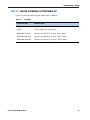
Table 7 Supported Mezzanine Cards
Product ID (PID) PID Description Connector
Virtual Interface Cards (VICs)
UCSB-MLOM-40G-01 Cisco UCS VIC 1240 modular LOM for M3 blade servers. Plugs into
the dedicated mLOM connector only. It is the only card that can be
plugged into the mLOM connector.
mLOM
UCS-VIC-M82-8P Cisco UCS VIC 1280 dual 40 Gb capable Virtual Interface Card PCIe

Cisco UCS B22 M3 Blade Server
CONFIGURING the SERVER
16
Supported Configurations
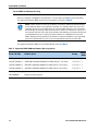
(1) Select One modular LOM and/or One PCIe Mezzanine Cards
Select one or two cards as desired in accordance with Table 8.
Table 8 Modular LOM and Mezzanine Card Options
Fabric
Extender
Compatibility
Card in
modular LOM
Connector
Card in Mezzanine Connector
(PCIe)
Ports Reference
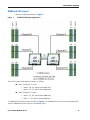
2208XP (PIDs UCS-IOM-2208XP, UCS-IOM2208-16FET)
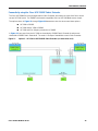
2208XP VIC 1240 None 4 x 10 Gb Figure 11 on page 38
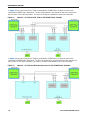
2208XP VIC 1240 VIC 1280 8 x 10 Gb Figure 12 on page 39
2208XP VIC 1240
3rd-party Mezzanine Card
1
Notes
1. To be supported in the future
6 x 10 Gb Figure 13 on page 39
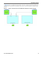
2208XP None
3rd-party Mezzanine Card
1
2 x 10 Gb Figure 14 on page 40
2204XP (PIDs UCS-IOM-2204XP, UCS-IOM2204-8FET)
2204XP VIC 1240 None 2 x 10 Gb Figure 15 on page 41
2204XP VIC 1240
VIC 1280
4 x 10 Gb Figure 16 on page 42
2204XP VIC 1240
3rd-party Mezzanine Card
1
4 x 10 Gb Figure 17 on page 42
2204XP None
3rd-party Mezzanine Card
1
2 x 10 Gb Figure 18 on page 43
2104XP (PID N20-I6584)
2104XP VIC 1240
None
2
2. The 2104XP fabric extender is not compatible with any I/O card installed in the mezzanine connector.
2 x 10 Gb Figure 19 on page 44

Cisco UCS B22 M3 Blade Server
17
CONFIGURING the SERVER
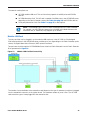
Also see Network Connectivity on page 35 for more information.
To help ensure that your operating system is compatible with the cards you have selected,
please check the Hardware Compatibility List at this URL:
http://www.cisco.com/en/US/products/ps10477/prod_technical_reference_list.html
Caveats
■ If a VIC 1240 modular LOM card is not installed, you must choose a network card to be
installed in the mezzanine card slot (see also
Network Connectivity on page 35)
■ The mezzanine cards are not supported for 1-CPU configurations. You must have two CPUs
installed before you can install and use mezzanine cards.

Cisco UCS B22 M3 Blade Server
CONFIGURING the SERVER
18
STEP 6 ORDER A TRUSTED PLATFORM MODULE
Trusted Platform Module (TPM) is a computer chip (microcontroller) that can securely store
artifacts used to authenticate the platform (server). These artifacts can include passwords,
certificates, or encryption keys. A TPM can also be used to store platform measurements that
help ensure that the platform remains trustworthy. Authentication (ensuring that the platform
can prove that it is what it claims to be) and attestation (a process helping to prove that a
platform is trustworthy and has not been breached) are necessary steps to ensure safer
computing in all environments.
The TPM ordering information is listed in Table 9.
Table 9 Trusted Platform Module
Product ID (PID) PID Description
UCSX-TPM1-001 Trusted Platform Module for UCS

Cisco UCS B22 M3 Blade Server
19
CONFIGURING the SERVER
STEP 7 ORDER CISCO FLEXIBLE FLASH SECURE DIGITAL CARDS
Dual SDHC flash card sockets are provided on the front left side of the server as shown in
Figure 4.
Figure 4 SD Locations
The SDHC card ordering information is listed in Table 10.
Future Supported Configurations
(1) Select one or two Cisco Flexible Flash secure digital card
NOTE: Cisco Flexible Flash secure digital cards are currently orderable; however,
they will be enabled only with future firmware and software updates.
Table 10 Cisco Flexible Flash Secure Digital Cards
Product ID (PID) PID Description
UCS-SD-16G 16 GB SD Card module for UCS Servers
NOTE: The SD card transfer rates are:
■ Sequential reads: 23 MB/s
■ Sequential writes: 20 MB/s
332219
Page is loading ...
Page is loading ...
Page is loading ...
Page is loading ...
Page is loading ...
Page is loading ...
Page is loading ...
Page is loading ...
Page is loading ...
Page is loading ...
Page is loading ...
Page is loading ...
Page is loading ...
Page is loading ...
Page is loading ...
Page is loading ...
Page is loading ...
Page is loading ...
Page is loading ...
Page is loading ...
Page is loading ...
Page is loading ...
Page is loading ...
Page is loading ...
Page is loading ...
Page is loading ...
-
 1
1
-
 2
2
-
 3
3
-
 4
4
-
 5
5
-
 6
6
-
 7
7
-
 8
8
-
 9
9
-
 10
10
-
 11
11
-
 12
12
-
 13
13
-
 14
14
-
 15
15
-
 16
16
-
 17
17
-
 18
18
-
 19
19
-
 20
20
-
 21
21
-
 22
22
-
 23
23
-
 24
24
-
 25
25
-
 26
26
-
 27
27
-
 28
28
-
 29
29
-
 30
30
-
 31
31
-
 32
32
-
 33
33
-
 34
34
-
 35
35
-
 36
36
-
 37
37
-
 38
38
-
 39
39
-
 40
40
-
 41
41
-
 42
42
-
 43
43
-
 44
44
-
 45
45
-
 46
46


Cisco UCS-CPU-E5-2470 Datasheet
- Category
- Processors
- Type
- Datasheet
Ask a question and I''ll find the answer in the document
Finding information in a document is now easier with AI
Related papers
-
Cisco UCS B22 M3 User manual
-
Cisco UCS-USBFLSH-S-4GB= Datasheet
-
-
-
Cisco UCS B200 M3 Specification
-
-
-
-
-
Cisco UCS B200 M4 Installation And Service Note
Other documents
-
Schonbek 1240-26S Operating instructions
-
Cisco Systems UCS C220 M3 User manual
-
-
-
-
Lenovo Balanced Memory Operating instructions
-
-
-
Whirlpool UXT4030AAB User manual
-
Dell PowerEdge C8000 Owner's manual