Combitherm 12-20esi

Alto-Shaam Combitherm 12-20esi User manual

  • Hello! I am an AI chatbot trained to assist you with the Alto-Shaam Combitherm 12-20esi User manual. I’ve already reviewed the document and can help you find the information you need or explain it in simple terms. Just ask your questions, and providing more details will help me assist you more effectively!
MN-29245 06/10
P R I N T E D I N U .S .A .
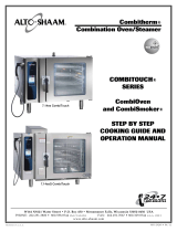
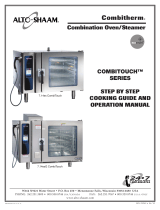
C o m b i t h e r m ®
C o m b i n a t i o n
O v e n / S t e a m e r
ES ELECTRIC
COM B ITO U C H
S ERI ES
610
1010
714
1018
1220
2020
VHes-5
VHes-10
I N STALLATION
W164 N9221 Water Street P.O. Box 450 Menomonee Falls, Wisconsin 53052-0450 USA
PHONE: 262.251.3800 800.558.8744 USA/CANADA FAX: 262.251.7067 800.329.8744 U.S.A. ONLY
WWW
.ALTO-SHAAM.COM
i
Delivery. . . . . . . . . . . . . . . . . . . . . . . . . . . . . . . . . . 1
Unpacking . . . . . . . . . . . . . . . . . . . . . . . . . . . . . . . . 1
Safety Procedures and Precautions . . . . . . . . . . . . 2
Installation
Site Requirements . . . . . . . . . . . . . . . . . . . . . . . 3
Ventilation Requirements . . . . . . . . . . . . . . . . . . 3
Positioning on Site . . . . . . . . . . . . . . . . . . . . . . . 4
Leveling . . . . . . . . . . . . . . . . . . . . . . . . . . . . . . . 5
Stand Installation . . . . . . . . . . . . . . . . . . . . . . . . 5
Common Specifications . . . . . . . . . . . . . . . . . . . 6
Specifications, 6•10es . . . . . . . . . . . . . . . . . . . . 7
Specifications, 6•10esi . . . . . . . . . . . . . . . . . . . . 8
Specifications, 6•10esiN . . . . . . . . . . . . . . . . . . . 9
Specifications, 10•10es . . . . . . . . . . . . . . . . . . 10
Specifications, 10•10esi . . . . . . . . . . . . . . . . . . 11
Specifications, 10•10esiN . . . . . . . . . . . . . . . . . 12
Specifications, 7•14es . . . . . . . . . . . . . . . . . . . 13
Specifications, 7•14esi . . . . . . . . . . . . . . . . . . . 14
Specifications, 10•18es . . . . . . . . . . . . . . . . . . 15
Specifications, 10•18esi . . . . . . . . . . . . . . . . . . 16
Specifications, 12•20es . . . . . . . . . . . . . . . . . . 17
Specifications, 12•20esi . . . . . . . . . . . . . . . . . . 18
Specifications, 20•20es . . . . . . . . . . . . . . . . . . 19
Specifications, 20•20esi . . . . . . . . . . . . . . . . . . 20
Electrical Connection . . . . . . . . . . . . . . . . . . . . 21
Drip Tray Installation. . . . . . . . . . . . . . . . . . . . . 23
Mobile Equipment Restraint . . . . . . . . . . . . . . . 23
Water Quality Requirement. . . . . . . . . . . . . . . . 24
Water Connections . . . . . . . . . . . . . . . . . . . . . . 25
Installation Checklist. . . . . . . . . . . . . . . . . . . . . 26
Combitouch Checklist . . . . . . . . . . . . . . . . . . . . 27
Error Codes . . . . . . . . . . . . . . . . . . . . . . . . . . . 28
Ventless Hood Option
Condensate Drain. . . . . . . . . . . . . . . . . . . . . . . 32
Filter Door Latch. . . . . . . . . . . . . . . . . . . . . . . . 32
Operation . . . . . . . . . . . . . . . . . . . . . . . . . . . . . 33
Warranty
Original Equipment Limited Warranty . . . . . . . . 34
Transportation Damage and Claims . . . . . . . . . 35
COMBITOUCH ES SERIES ELECTRIC INSTALLATION MANUAL 1.
D E L I V E R Y
This Alto-Shaam appliance has been
thoroughly tested and inspected to ensure only the
highest quality unit is provided. Upon receipt,
check for any possible shipping damage and report
it at once to the delivering carrier. See
Transportation Damage and Claims section
located in this manual.
This appliance, complete with unattached
items and accessories, may have been delivered in
one or more packages. Check to ensure that all
standard items and options have been received
with each model as ordered.
Save all the information and instructions
packed with the appliance. Complete and return
the warranty card to the factory as soon as
possible to ensure prompt service in the event of a
warranty parts and labor claim.
This manual must be read and understood by
all people using or installing the equipment
model. Contact the Alto-Shaam Tech Team Service
Department if you have any questions concerning
installation, operation, or maintenance.
NOTE: All claims for warranty must include the
full model number and serial number of
the unit.
U N P A C K I N G
1. Carefully remove the
appliance from the
carton or crate.
NOTE: Do not discard the
carton and other
packaging material
until you have
inspected the unit
for hidden damage
and tested it for
proper operation.
2. Read all instructions in this manual carefully
before initiating the installation of this appliance.
DO NOT DISCARD THIS MANUAL.
This manual is considered to be part of the
appliance and is to be provided to the owner or
manager of the business or to the person
responsible for training operators. Additional
manuals are available from the Alto-Shaam
Tech Team Service Department.
3. Remove all protective plastic film, packaging
materials, and accessories from the appliance
before connecting electrical power. Store any
accessories in a convenient place for future use.
®
®
LES INFORMATIONS CONTENUES DANS CE
MANUEL SONT IMPORTANTES POUR
LINSTALLATION LUTILISATION ET
LENTRETIEND DE CE FOUR. SIL VOUS
PLAIT LISEZ-LE TRES ATTENTIVEMENT ET
CONSERVEZ-LE.
LA NON-APPLICATION DE CES CONSIGNES
ANNULE TOUTES GARANTIES.
THE INFORMATION CONTAINED IN THIS
MANUAL IS IMPORTANT FOR THE PROPER
INSTALLATION OF THIS OVEN. PLEASE
READ CAREFULLY AND RETAIN FOR
FUTURE REFERENCE.
IMPROPER CONNECTION OF THIS
APPLIANCE WILL NULLIFY ALL
WARRANTIES.
C A U T I O N
TO PREVENT PERSONAL INJURY,
USE CAUTION WHEN MOVING OR
LEVELING THIS APPLIANCE.
COMBITOUCH ES SERIES ELECTRIC INSTALLATION MANUAL 2.
N O T E
For equipment delivered for use
in any location regulated by the
following directive:
DO NOT DISPOSE OF ELECTRICAL
OR ELECTRONIC EQUIPMENT WITH
OTHER MUNICIPAL WASTE.
C A U T I O N
WHEN WELDING ANY STAINLESS
STEEL COMPONENTS ON THIS
APPLIANCE, THE ELECTRONIC
CONTROL BOARDS MUST BE
ISOLATED FROM THE APPLIANCE.
1. This appliance is intended to cook, hold or
process foods for the purpose of human
consumption. No other use for this appliance is
authorized or recommended.
2. This appliance is intended for use in
commercial establishments where all operators
are familiar with the purpose, limitations, and
associated hazards of this appliance. Operating
instructions and warnings must be read and
understood by all operators and users.
3. Any troubleshooting guides, component views,
and parts lists included in this manual are for
general reference only and are intended for use
by qualified technical personnel.
4. This manual should be considered a permanent
part of this appliance. This manual and all
supplied instructions, diagrams, schematics,
parts lists, notices, and labels must remain with
the appliance if the item is sold or moved to
another location.
N O T E : Used to notify personnel of
installation, operation, or
maintenance information that is
important but not hazard related.
C A U T I O N
Used to indicate the presence of a hazard that can
or will cause minor personal injury, property
damage, or a potential unsafe practice if the
warning included with this symbol is ignored.
C A U T I O N
Used to indicate the presence of a
hazard that can or will cause minor or
moderate personal injury or property
damage if the warning included with
this symbol is ignored.
D A N G E R
Used to indicate the presence of a
hazard that WILL cause severe
personal injury, death, or substantial
property damage if the warning
included with this symbol is ignored.
W A R N I N G
Used to indicate the presence of a
hazard that CAN cause personal
injury, possible death, or major
property damage if the warning
included with this symbol is ignored.
SAFETY PROCEDURES
AND PRECAUTIONS
Knowledge of proper procedures is essential to the
safe operation of electrically and/or gas energized
equipment. In accordance with generally accepted
product safety labeling guidelines for potential
hazards, the following signal words and symbols
may be used throughout this manual.
COMBITOUCH ES SERIES ELECTRIC INSTALLATION MANUAL 3.
S I T E I N S T A L L A T I O N
I N S T A L L A T I O N
D A N G E R
IMPROPER INSTALLATION,
ALTERATION, ADJUSTMENT,
SERVICE, OR MAINTENANCE COULD
RESULT IN SEVERE INJURY, DEATH,
OR CAUSE PROPERTY DAMAGE.
READ THE INSTALLATION,
OPERATING AND MAINTENANCE
INSTRUCTIONS THOROUGHLY
BEFORE INSTALLING OR SERVICING
THIS EQUIPMENT.
C A U T I O N
TO PREVENT PERSONAL INJURY,
USE CAUTION WHEN MOVING OR
LEVELING THIS APPLIANCE.
D A N G E R
DO NOT store or use gasoline or other
flammable vapors or liquids in the
vicinity of this or any other appliance .
D A N G E R
AVERTISSEMENT : UNE INSTALLATION,
UN AJUSTEMENT, UNE ALTÉRATION,
UN SERVICE OU UN ENTRETIEN NON
CONFORME AUX NORMES PEUT
CAUSER
D
ES DOMMAGES À LA PROPRIÉTÉ, DES
B
LESSURES OU LA MORT.
LIRE ATTENTIVEMENT LES DIRECTIVES
D’OPÉRATION ET D’ENTRETIEN AVANT
DE FAIRE L’INSTALLATION, OU
S I T E I N S T A L L A T I O N
I N S TA L L AT I O N C O D E S &
S TA N D A R D S
The following codes and standards are required
for installation of this oven: AIR SUPPLY,
ELECTRICAL CONNECTIONS, WATER
CONNECTIONS, AND WASTE WATER
DISCHARGE.
N O T E :
Where automatically operated appliances are
vented through a ventilating hood or exhaust
system equipped with a damper or with a power
means of exhaust, provisions shall be made to
allow the equipment to operate only when the
damper is open to a position to properly vent the
appliance and when the power means of exhaust
is in operation.
IN ACCORDANCE WITH NFPA 54
COMMONWEALTH OF MASSACHUSETTS ONLY.
VENTILATION REQUIREMENTS
A steam ventilation hood is mandatory for the
operation of the oven. The ventilation hood must
be installed in accordance with local building codes
for the steam exhaust and must protrude 12-inches
to 20-inches (300 to 500mm) over the front side of
the oven. A grease filter must be located in the
protruding area of the hood. Grease filters should
be thoroughly cleaned on a regular basis following
manufacturer's instruction. Ventilation hoods must
ensure an adequate amount of incoming air during
operation and must be operated whenever the
combination oven/steamer is used in order to avoid
the accumulation of condensation in the hood area.
COMBITOUCH ES SERIES ELECTRIC INSTALLATION MANUAL 4.
THE OVEN MUST REMAIN ON
THE PALLET WHILE BEING
MOVED TO THE INSTALLATION
SITE BY FORK LIFT OR
PALLET LIFT TRUCK.
N O T E : Note dimensions required for doorways
and aisles for access of the oven and
pallet to the installation site. Transport
the oven in an upright and level position
only. Do not tilt the oven.
®
S I T E I N S T A L L A T I O N
I N S T A L L A T I O N
POSITIONING ON SITE
Lift the oven from the pallet with a fork lift or pallet
lift truck positioned at the front of the oven. For
damage protection, the use of two wooden boards,
placed between the bottom of the oven and the
lifting forks, is strongly recommended. To avoid
damage, position the lift forks to the left of the
condenser and right of the right leg as indicated in
the diagram above.
Stand the oven in a level position. Use the
adjustable feet to overcome an uneven floor and
ensure that the unit is level.
It is strongly recommended that table top models be
mounted on a factory supplied stand or a stand that
is stable, open, and level. Recommended height is
23-inches (584mm).
Adjust the height of floor models for smooth access
of the trolley or cart. When positioning the oven,
observe the minimum space allocation requirements
shown.
To insure proper operation, the installation of this
oven must be completed by qualified technicians in
accordance with the instructions provided in this
manual. Failure to follow the instructions provided
may result in damage to the oven, building, or
cause personal injury to personnel.
MINIMUM CLEARANCE REQUIREMENTS
LEFT SIDE 6" (152mm) MINIMUM
18" (457mm) SERVICE ACCESS RE COMMENDED
20" (508mm) FROM HEAT PRODUCING EQUIPMENT
RIGHT SIDE 4" (102mm)
BACK 4" (102mm) FOR PLUMBING
TOP 20" (508mm) FOR AIR MOVEMENT
NOTE: Additional clearance is needed for service
access. A minimum distance of 18-inches is
strongly recommended. If adequate service
clearance is not provided, it will be necessary to
disconnect the gas, water, and drain to move the
oven with a fork lift for service access. Charges in
connection with inadequate service access is not
covered under warranty.
NOTE: To avoid equipment damage, observe
attention label on oven for area to avoid
with lifting fork.
COMBITOUCH ES SERIES ELECTRIC INSTALLATION MANUAL 5.
S I T E I N S T A L L A T I O N
I N S T A L L A T I O N
POSITIONING REQUIREMENTS
In order to ensure proper ventilation, a minimum
distance of at least 6-inches (152mm) must be kept from
the control panels side (left) of the oven and any
adjoining surfaces.
NOTE: Additional clearance is needed for service access.
A minimum distance of 18-inches is strongly
recommended. If adequate service clearance is not
provided, it will be necessary to disconnect the gas, water,
and drain to move the oven with a fork lift for service
access. Charges in connection with inadequate service
access is not covered under warranty.
Allow a minimum of 4-inches (102mm) from the right
side of the oven to allow the door to open to at least a
90° angle. Fully opened, the door will extend up to a
225° angle If the oven is furnished with the retractable
door option, allow a minimum clearance of
6-1/2 inches (165mm).
Allow a minimum clearance of 4-inches (102mm) from
the back of the oven for plumbing connections.
Allow a 20-inch (500mm) clearance at the top of the
oven for free air movement and for the steam vent(s)
located at the top.
Do not install the oven adjacent to heat producing
equipment such as fryers, broilers, etc. Heat from such
appliances may cause damage to the controls of the
Combitherm. Minimum clearance recommended:
20-inches (500mm)
Place the Combitherm oven on a stable, non-combustible
level horizontal surface. For countertop models, the oven
stand must be level. Level from front-to-back and side-to-
side by means of the
adjustable legs. In
addition, the overall
height of the oven
should be positioned so the operating controls and shelves
may be conveniently reached from the front.
When placing a countertop model on an oven stand,
position the oven legs on the outside of the
positioning pins.
Positioning
Pins
Positioning
Pins
COMBITOUCH ES SERIES ELECTRIC INSTALLATION MANUAL 6.
COMMON SPECIFICATIONS
CombiGuard BWS Blended Water System
(INCLUDES 50 GALLON TANK, 1 MEMBRANE & 3 FILTERS) FI-28727
CombiGuard BWS Replacement Filter
Cartridge AMS-QT FI-29316
CombiGuard BWS Replacement Filter
Cartridge SCLX2-Q FI-29317
CombiGuard BWS Replacement Prefilter
Filter Cartridge CTO-Q FI-29318
CombiGuard Triple-Guard Water Filtration System
(INCLUDES 1 CARTRIDGE)
610, 714, 1018 (CombiGuard 10) FI-23014
1220 (CombiGuard 20) FI-28728
CombiGuard Triple-Guard Replacement Filter
610, 1010, 714, 1018 (CombiGuard 10) FI-26356
1220, 2020 (CombiGuard 20) FI-28744
Fry Basket, 12" X 20" (325mm x 530mm) BS-26730
Grilling Grate, 12" X 20" (325mm x 530mm) SH-26731
Shelf, Stainless Steel Wire
610, 1010 SH-2903
714, 1018 SH-22584
1220, 2020 SH-22473
Probe, Sous Vide PR-34747
Combitherm Cleaning Liquid CE-24750
SPECIALLY FORMULATED FOR COMBITHERM OVENS
TWELVE (12) CONTAINERS/CASE, 1 QUART (C. 1 LITER) EACH
Combiclean Tablets CE-28892
SPECIALLY FORMULATED FOR COMBITHERM OVENS
TWO (2) CONTAINERS/BOX, 90 PACKETS EACH CONTAINER
Scale Free CE-27889
(
CITRUS BASED, NON-CORROSIVE DELIMING PRODUCT)
CASE = FOUR 4-LB BOTTLES; 4-LB BOTTLE MAKES 10 GALLONS
Service Start-Up Check SPECIFY AS REQUIRED
AVAILABLE THROUGH THE ALTO
-SHAAM TECH TEAM SERVICE DEPARTMENT
Six (6) Chicken Roasting Rack
(PAN NOT INCLUDED) SH-23000
Fry Basket BS-26730
Grilling Grate SH-26731
Ten (10) Chicken Roasting Rack
SH-22634
I N S T A L L A T I O N
COMBITOUCH ES SERIES ELECTRIC INSTALLATION MANUAL 7.
31-3/8" (796mm)
34-1/16" (864mm)
17-15/16"
(456mm)
7-9/16"
(191mm)
W
ATER
D
RAIN
33-1/8" (840mm)
4-15/16"
(
125mm)
Steam Vent (Top)
60-9/16" (1538mm)
Water Drain
(
Back)
Treated Water
Intake (Bottom)
Untreated Water
Intake (Bottom)
Electrical Connection
(Bottom)
30" (761mm)
3
-5/8" (92mm)
2-1/8" (53mm)
11-1/8"
(282mm)
6-3/8" (161mm)
41-15/16" (1064mm)
43-7/8" (1114mm)
2" (50mm)
49-1/8" (1247mm)
15-3/4"
(400mm)
13-1/2"
(342mm)
35-3/16" (893mm)
27-11/16"
(702mm)
7-9/16"
(192mm)
W E I G HT
NET 285 lb (129 kg)
SHIP 465 lb (211 kg)
CRATE DIMENSIONS: (LXWXH)
53" X 45" X 49"
(1346 x 1143 x 1245mm)
D I M E NS IO N S : H x W x D
EXTERIOR:
35-3/16" x 43-7/8" x 34-1/16" (893mm x 1114mm x 864mm)
EXTERIOR WITH RECESSED DOOR:
35-3/16" x 47-7/8" x 34-1/16" (893mm x 1216mm x 864mm)
I
NTERIOR
:
17-3/4" x 23-1/2" x 21-1/16" (450mm x 597mm x 535mm)
*ADDITIONAL WIRE SHELVES REQUIRED FOR MAXIMUM CAPACITY
I N S TA L L AT I O N R E Q UI RE M EN TS
Oven must be installed level.
Hood installation is required.
Water supply shut-off valve and back-flow preventer.
6•10ES
C A PA CI T Y
FULL-SIZE PANS: 20" x 12" x 2-1/2" Six (6)
GN 1/1: 530 x 325 x 65mm Six (6)
GN 2/1: 650 x 530 x 65mm Three (3)
HALF-SIZE SHEET PANS:* 18" x 13" x 1" Six (6)
ON WIRE SHELVES ONLY
72 lb (33 kg) MAXIMUM
VOLUME MAXIMUM
: 45 quarts (57 liters)
E L E C T R IC A L ( D E D I C A T E D C I R C U I T R E Q U I R E D )
VOLTAGE PHASE CYCLE/HZ AWG AMPS kW
at 208 1* 60 2 Wire plus ground 40.8 8.5
at 240 AWG 6 47.0 11.2
at 208 3 60 3 Wire plus ground 23.5/ph 8.5
at 240 AWG 8 27.0/ph 11.2
at 380 3 50 4 Wire plus ground 13.0/ph 8.5
at 415 AWG 12 16.0/ph 11.2
at 440 3* 60 3 Wire plus ground 11.2/ph 8.5
at 480 AWG 8 13.5/ph 11.2
* ELECTRICAL SERVICE CHARGE APPLIES
208-240
208-240
380-415
440-480
CL E A R AN C E RE Q U I RE M E N TS
L E FT : 6" (152mm) RECOMMENDED SERVICE ACCESS: 18" (457mm)
20" (508mm) FROM HEAT PRODUCING EQUIPME N T
R I GH T : 4" (102mm) TO P : 20" (508mm) FOR AIR MOVEMENT
B A CK
: 4" (102mm) B O TT O M: 5-1/8" (130mm) FOR LEGS
WAT E R R E Q UI R E M EN T S
TWO (2) COLD WATER INLETS - DRINKING QUALITY
ONE (1) TREATED WATER INLET: 3/4" NPT*
ONE (1) UNTREATED WATER INLET: 3/4" NPT*
LINE PRESSURE: 30 to 90 psi 2.8 to 6.2 bar
WATER DRAIN: 1-1/2"
CONNECTION WITH A 2" MINIMUM AIR GAP
INSTALLED AS CLOSE TO THE OVEN AS POSSIBLE
WAT E R Q U A LI T Y MI N I M UM S TAND A R D S
USING A WATER SUPPLY NOT MEETING ALTO-SHAAM'S
MINIMUM WATER QUALITY STANDARDS WILL VOID THIS
WARRANTY. It is the responsibility of the purchaser to ensure that
incoming water supply is compliant with the specifications listed
through adequate treatment measures. Installation of the
CombiGuard™ Water Filtration System is recommended, but this
system may not address all water quality issues present.
Contaminant Inlet Water Requirements (untreated water)
Free Chlorine Less than 0.1 ppm (mg/L)
Hardness Less than 3 gpg (52 ppm)
Chloride Less than 30 ppm (mg/L)
pH 7.0 to 8.5
Alkalinity Less than 50 ppm (mg/L)
Silica Less than 12 ppm (mg/L)
Total Dissolved
Solids (tds) Less than 60 ppm
* Can manifold off
of one 3/4" line.
COMBITOUCH ES SERIES ELECTRIC INSTALLATION MANUAL 8.
31-3/8" (796mm)
34-1/16" (864mm)
1
7-15/16"
(
456mm)
7-9/16"
(191mm)
WATER
DRAIN
33-1/8" (840mm)
4-15/16"
(125mm)
Steam Vent (Top)
60-9/16" (1538mm)
Water Drain
(Back)
Treated Water
Intake (Bottom)
Untreated Water
I
ntake (Bottom)
Electrical Connection
(Bottom)
30" (761mm)
3-5/8" (92mm)
2
-1/8" (53mm)
11-1/8"
(282mm)
6-3/8" (161mm)
41-15/16" (1064mm)
4
3-7/8" (1114mm)
2" (50mm)
4
9-1/8" (1247mm)
15-3/4"
(400mm)
13-1/2"
(342mm)
35-3/16" (893mm)
27-11/16"
(702mm)
7-9/16"
(192mm)
D I M E NS IO N S : H x W x D
EXTERIOR:
35-3/16" x 43-7/8" x 34-1/16" (893mm x 1114mm x 864mm)
EXTERIOR WITH RECESSED DOOR:
35-3/16" x 47-7/8" x 34-1/16" (893mm x 1216mm x 864mm)
I
NTERIOR
:
20-5/16" x 23-1/2" x 28-7/8" (515mm x 596mm x 722mm)
*ADDITIONAL WIRE SHELVES REQUIRED FOR MAXIMUM CAPACITY
I N S TA L L AT I O N R E Q UI RE M EN TS
Oven must be installed level.
Hood installation is required.
Water supply shut-off valve and back-flow preventer.
6•10ESi
C A PA CI T Y
FULL-SIZE PANS: 20" x 12" x 2-1/2" Six (6) Six (6)
GN 1/1: 530 x 325 x 65mm Six (6) Six (6)
HALF-SIZE SHEET PANS:* 18" x 13" x 1" Six (6) Six (6)
ON WIRE SHELVES ONLY
72 lb (33 kg) MAXIMUM
VOLUME MAXIMUM
: 45 quarts (57 liters)
W E I G HT
NET 285 lb (129 kg)
SHIP 415 lb (188 kg)
CRAT E DIMENS I ONS: (LXWXH)
53" X 45" X 49"
(1346 x 1143 x 1245mm)
E L E C T R IC A L ( D E D I C ATE D C I R C U I T R E Q U I R E D ) 6 1 0 E S i 6 1 0 E S i/ s k
VOLTAGE PHASE CYCLE/ HZ AWG AMPS kW AMPS kW
at 208 1* 60 2 Wire plus ground 41.0 8.5 43.3 9.0
at 240 AWG 6 47.0 11.2 48.7 11.7
at 208 3 60 3 Wire plus ground 23.3/ph 8.5 25.0/ph 9.0
at 240 AWG 8 27.0/ph 11.2 28.2/ph 11.7
at 380 3 50 4 Wire plus ground 13.0/ph 8.5 14.0/ph 9.0
at 415 AWG 12 15.6/ph 11.2 16.3/ph 11.7
at 440 3* 60 3 Wire plus ground 11.0/ph 8.5 12.0/ph 9.0
at 480 AWG 8 13.0/ph 11.2 14.0/ph 11.7
* ELECTRICAL SERVICE CHARGE APPLIES
208-240
208-240
380-415
440-480
CL E A R AN C E RE Q U I RE M E N TS
L E FT : 6" (152mm) RECOMMENDED SERVICE ACCESS: 18" (457mm)
20" (508mm) FROM HEAT PRODUCING EQUIPME N T
R I GH T : 4" (102mm) TO P : 20" (508mm) FOR AIR MOVEMENT
B A CK
: 4" (102mm) B O TT O M: 5-1/8" (130mm) FOR LEGS
WAT E R R E Q UI R E M EN T S
TWO (2) COLD WATER INLETS - DRINKING QUALITY
ONE (1) TREATED WATER INLET: 3/4" NPT*
ONE (1) UNTREATED WATER INLET: 3/4" NPT*
LINE PRESSURE: 30 to 90 psi 2.8 to 6.2 bar
WATER DRAIN: 1-1/2"
CONNECTION WITH A 2" MINIMUM AIR GAP
INSTALLED AS CLOSE TO THE OVEN AS POSSIBLE
WAT E R Q U A LI T Y MI N I M UM S TAND A R D S
USING A WATER SUPPLY NOT MEETING ALTO-SHAAM'S
MINIMUM WATER QUALITY STANDARDS WILL VOID THIS
WARRANTY. It is the responsibility of the purchaser to ensure that
incoming water supply is compliant with the specifications listed
through adequate treatment measures. Installation of the
CombiGuard™ Water Filtration System is recommended, but this
system may not address all water quality issues present.
Contaminant Inlet Water Requirements (untreated water)
Free Chlorine Less than 0.1 ppm (mg/L)
Hardness Less than 3 gpg (52 ppm)
Chloride Less than 30 ppm (mg/L)
pH 7.0 to 8.5
Alkalinity Less than 50 ppm (mg/L)
Silica Less than 12 ppm (mg/L)
Total Dissolved
Solids (tds) Less than 60 ppm
* Can manifold off
of one 3/4" line.
COMBITOUCH ES SERIES ELECTRIC INSTALLATION MANUAL 9.
32-15/16" (835mm)
3
5-9/16" (903mm)
2
1-11/16"
(
550mm)
7
-1/2"
(
190mm)
6-3/8" (161mm)
WATER
DRAIN
3
3-7/8" (859mm)
35-13/16" (909mm)
2" (50mm)
41-1/16" (1042mm)
W
ater Drain
(
Side Back)
Steam Vent
(Top)
Electrical Connection
(Bottom)
21-7/8"
(555mm)
3-5/8" (92mm)
2-1/16" (52mm)
19-1/2"
(495mm)
12-5/16"
(312mm)
9-9/16"
(242mm)
2
5"
(
635mm)
5"
(126mm)
35-3/16" (893mm)
54-1/8" (1374mm)
26-3/4"
(679mm)
7-9/16"
(192mm)
Treated Water
Intake (Bottom)
Untreated Water
Intake (Bottom)
D I M E NS IO N S : H x W x D
EXTERIOR:
35-3/16" x 35-13/16" x 35-9/16" (893mm x 909mm x 903mm)
EXTERIOR WITH RECESSED DOOR:
35-3/16" x 39-13/16" x 35-9/16" (893mm x 1011mm x 903mm)
I
NTERIOR
:
17-3/4" x 13-1/4" x 26-1/4" (450mm x 387mm x 665mm)
*ADDITIONAL WIRE SHELVES REQUIRED FOR MAXIMUM CAPACITY
I N S TA L L AT I O N R E Q UI RE M EN TS
Oven must be installed level.
Hood installation is required.
Water supply shut-off valve and back-flow preventer.
6•10ESiN
C A PA CI T Y
FULL-SIZE PANS: 20" x 12" x 2-1/2" Six (6)
GN 1/1: 530 x 325 x 65mm Six (6)
HALF-SIZE PANS: 10" x 12" x 2-1/2" Twelve (12)
GN 1/2: 265 x 325 x 65mm Twelve (12)
HALF-SIZE SHEET PANS:* 18" x 13" x 1" Six (6)
ON WIRE SHELVES ONLY
72 lb (33 kg) MAXIMUM
VOLUME MAXIMUM
: 45 quarts (57 liters)
W E I G HT
NET 285 lb (129 kg)
SHIP 415 lb (188 kg)
CRATE DIMENSIONS: (LXWXH)
53" X 45" X 49"
(1346 x 1143 x 1245mm)
E L E C T R IC A L ( D E D I C ATE D C I R C U I T R E Q U I R E D ) 6 1 0 E S iN 6 1 0 E S iN / s k
VOLTAGE PHASE CYCLE/HZ AWG AMPS kW AMPS kW
at 208 1* 60 2 Wire plus ground 41.0 8.5 43.3 9.0
at 240 AWG 6 47.0 11.2 48.7 11.7
at 208 3 60 3 Wire plus ground 23.3/ph 8.5 25.0/ph 9.0
at 240 AWG 8 27.0/ph 11.2 28.2/ph 11.7
at 380 3 50 4 Wire plus ground 13.0/ph 8.5 14.0/ph 9.0
at 415 AWG 12 15.6/ph 11.2 16.3/ph 11.7
at 440 3* 60 3 Wire plus ground 11.0/ph 8.5 12.0/ph 9.0
at 480 AWG 8 13.0/ph 11.2 14.0/ph 11.7
* ELECTRICAL SERVICE CHARGE APPLIES
208-240
208-240
380-415
440-480
CL E A R AN C E RE Q U I RE M E N TS
L E FT : 6" (152mm) RECOMMENDED SERVICE ACCESS: 18" (457mm)
20" (508mm) FROM HEAT PRODUCING EQUIPME N T
R I GH T : 4" (102mm) TO P : 20" (508mm) FOR AIR MOVEMENT
B A CK
: 4" (102mm) B O TT O M: 5-1/8" (130mm) FOR LEGS
WAT E R R E Q UI R E M EN T S
TWO (2) COLD WATER INLETS - DRINKING QUALITY
ONE (1) TREATED WATER INLET: 3/4" NPT*
ONE (1) UNTREATED WATER INLET: 3/4" NPT*
LINE PRESSURE: 30 to 90 psi 2.8 to 6.2 bar
WATER DRAIN: 1-1/2"
CONNECTION WITH A 2" MINIMUM AIR GAP
INSTALLED AS CLOSE TO THE OVEN AS POSSIBLE
WAT E R Q U A LI T Y MI N I M UM S TAND A R D S
USING A WATER SUPPLY NOT MEETING ALTO-SHAAM'S
MINIMUM WATER QUALITY STANDARDS WILL VOID THIS
WARRANTY. It is the responsibility of the purchaser to ensure that
incoming water supply is compliant with the specifications listed
through adequate treatment measures. Installation of the
CombiGuard™ Water Filtration System is recommended, but this
system may not address all water quality issues present.
Contaminant Inlet Water Requirements (untreated water)
Free Chlorine Less than 0.1 ppm (mg/L)
Hardness Less than 3 gpg (52 ppm)
Chloride Less than 30 ppm (mg/L)
pH 7.0 to 8.5
Alkalinity Less than 50 ppm (mg/L)
Silica Less than 12 ppm (mg/L)
Total Dissolved
Solids (tds) Less than 60 ppm
* Can manifold off
of one 3/4" line.
COMBITOUCH ES SERIES ELECTRIC INSTALLATION MANUAL 10.
D I M E NS IO N S : H x W x D
EXTERIOR:
41-1/2" x 43-7/8" x 34-1/16" (1053mm x 1114mm x 865mm)
EXTERIOR WITH RECESSED DOOR:
41-1/2" x 47-7/8" x 34-1/16" (1053mm x 1216mm x 865mm)
I
NTERIOR
:
27" x 23-1/2" x 21-1/16" (685mm x 597mm x 535mm)
*ADDITIONAL WIRE SHELVES REQUIRED FOR MAXIMUM CAPACITY
I N S TA L L AT I O N R E Q UI RE M EN TS
Oven must be installed level.
Hood installation is required.
Water supply shut-off valve and back-flow preventer.
10•10ES
C A PA CI T Y
FULL-SIZE PANS: 20" x 12" x 2-1/2" Ten (10)
GN 1/1: 530 x 325 x 65mm Ten (10)
GN 2/1: 650 x 530 x 65mm Five (5)
HALF-SIZE SHEET PANS:* 18" x 13" x 1" Ten (10)
ON WIRE SHELVES ONLY
120 lb (54 kg) MAXIMUM
VOLUME MAXIMUM
: 75 quarts (95 liters)
W E I G HT
NET 385 lb (175 kg)
SHIP 525 lb (238 kg)
CRATE DIMENSIONS: (LXWXH)
53" X 45" X 49"
(1346 x 1143 x 1245mm)
E L E C T R IC A L ( D E D I C ATE D C I R C U I T R E Q U I R E D )
VOLTAGE PHASE CYCLE/ HZ AWG AMPS kW
at 208 1* 60 2 Wire plus ground 67.0 13.9
at 240 AWG 3 77.0 18.4
at 208 3 60 3 Wire plus ground 38.5/ph 13.9
at 240 AWG 6 44.0/ph 18.4
at 380 3 50 4 Wire plus ground 21.5/ph 13.9
at 415 AWG 10 25.6/ph 18.4
at 440 3* 60 3 Wire plus ground 20.0/ph 15.4
at 480 AWG 8 22.0/ph 18.4
* ELECTRICAL SERVICE CHARGE APPLIES
208-240
208-240
380-415
440-480
CL E A R AN C E RE Q U I RE M E N TS
L E FT : 6" (152mm) RECOMMENDED SERVICE ACCESS: 18" (457mm)
20" (508mm) FROM HEAT PRODUCING EQUIPME N T
R I GH T : 4" (102mm) TO P : 20" (508mm) FOR AIR MOVEMENT
B A CK
: 4" (102mm) B O TT O M: 5-1/8" (130mm) FOR LEGS
WAT E R R E Q UI R E M EN T S
TWO (2) COLD WATER INLETS - DRINKING QUALITY
ONE (1) TREATED WATER INLET: 3/4" NPT*
ONE (1) UNTREATED WATER INLET: 3/4" NPT*
LINE PRESSURE: 30 to 90 psi 2.8 to 6.2 bar
WATER DRAIN: 1-1/2"
CONNECTION WITH A 2" MINIMUM AIR GAP
INSTALLED AS CLOSE TO THE OVEN AS POSSIBLE
WAT E R Q U A LI T Y MI N I M UM S TAND A R D S
USING A WATER SUPPLY NOT MEETING ALTO-SHAAM'S
MINIMUM WATER QUALITY STANDARDS WILL VOID THIS
WARRANTY. It is the responsibility of the purchaser to ensure that
incoming water supply is compliant with the specifications listed
through adequate treatment measures. Installation of the
CombiGuard™ Water Filtration System is recommended, but this
system may not address all water quality issues present.
Contaminant Inlet Water Requirements (untreated water)
Free Chlorine Less than 0.1 ppm (mg/L)
Hardness Less than 3 gpg (52 ppm)
Chloride Less than 30 ppm (mg/L)
pH 7.0 to 8.5
Alkalinity Less than 50 ppm (mg/L)
Silica Less than 12 ppm (mg/L)
Total Dissolved
Solids (tds) Less than 60 ppm
* Can manifold off
of one 3/4" line.
COMBITOUCH ES SERIES ELECTRIC INSTALLATION MANUAL 11.
33-1/16" (840mm) 4-15/16"
(125mm)
41-1/2" (1053mm)
33-15/16" (861mm)
7-9/16" (192mm)
60-9/16" (1538mm)
W
ater Drain
(Back)
30" (761mm)
2" (50mm)
46-7/8" (1190mm)
4
3-7/8" (1114mm)
31-3/8" (796mm)
34-1/16" (865mm)
17-15/16"
(456mm)
7-9/16"
(191mm)
Water Drain
6-1/4" (158mm)
41-15/16" (1064mm)
Steam Vent (Top)
Electrical Connection (Bottom)
T
reated Water
Intake (Bottom)
Untreated Water
Intake (Bottom)
2-1/8" (53mm)
3-5/8" (92mm)
11-1/8"
(282mm)
15-3/4"
(400mm)
13-1/2"
(342mm)
D I M E NS IO N S : H x W x D
EXTERIOR:
41-1/2" x 43-7/8" x 34-1/16" (1053mm x 1114mm x 865mm)
EXTERIOR WITH RECESSED DOOR:
41-1/2" x 47-7/8" x 34-1/16" (1053mm x 1216mm x 865mm)
I
NTERIOR
:
27" x 23-1/2" x 21-1/16" (685mm x 597mm x 535mm)
*ADDITIONAL WIRE SHELVES REQUIRED FOR MAXIMUM CAPACITY
I N S TA L L AT I O N R E Q UI RE M EN TS
Oven must be installed level.
Hood installation is required.
Water supply shut-off valve and back-flow preventer.
10•10ESi
C A PA CI T Y
FULL-SIZE PANS: 20" x 12" x 2-1/2" Ten (10) Eight (8)
GN 1/1: 530 x 325 x 65mm Ten (10) Eight (8)
HALF-SIZE SHEET PANS:* 18" x 13" x 1" Ten (10) Nine (9)
ON WIRE SHELVES ONLY
120 lb (54 kg) MAXIMUM
VOLUME MAXIMUM
: 75 quarts (95 liters)
W E I G HT
NET 385 lb (175 kg)
SHIP 495 lb (225 kg)
CRAT E DIMENS I ONS: (LXWXH) EST
53" X 45" X 49"
(1346 x 1143 x 1245mm)
E L E C T R IC A L ( D E D I C ATE D C I R C U I T R E Q U I R E D ) 1 0 1 0 E S i 1 0 1 0 E S i / s k
VOLTAGE PHASE CYCLE/ HZ AWG AMPS kW AMPS kW
at 208 1* 60 2 Wire plus ground 67.0 13.9 69.2 14.4
at 240 AWG 3 77.0 18.4 79.0 18.9
at 208 3 60 3 Wire plus ground 38.6/ph 13.9 40.0/ph 14.4
at 240 AWG 6 44.3/ph 18.4 45.5/ph 18.9
at 380 3 50 4 Wire plus ground 21.1/ph 13.9 22.0/ph 14.4
at 415 AWG 10 25.6/ph 18.4 26.3/ph 18.9
at 440 3* 60 3 Wire plus ground 20.0/ph 15.4 21.0/ph 15.9
at 480 AWG 8 22.0/ph 18.4 23.0/ph 18.9
* ELECTRICAL SERVICE CHARGE APPLIES
208-240
208-240
380-415
440-480
CL E A R AN C E RE Q U I RE M E N TS
L E FT : 6" (152mm) RECOMMENDED SERVICE ACCESS: 18" (457mm)
20" (508mm) FROM HEAT PRODUCING EQUIPME N T
R I GH T : 4" (102mm) TO P : 20" (508mm) FOR AIR MOVEMENT
B A CK
: 4" (102mm) B O TT O M: 5-1/8" (130mm) FOR LEGS
WAT E R R E Q UI R E M EN T S
TWO (2) COLD WATER INLETS - DRINKING QUALITY
ONE (1) TREATED WATER INLET: 3/4" NPT*
ONE (1) UNTREATED WATER INLET: 3/4" NPT*
LINE PRESSURE: 30 to 90 psi 2.8 to 6.2 bar
WATER DRAIN: 1-1/2"
CONNECTION WITH A 2" MINIMUM AIR GAP
INSTALLED AS CLOSE TO THE OVEN AS POSSIBLE
WAT E R Q U A LI T Y MI N I M UM S TAND A R D S
USING A WATER SUPPLY NOT MEETING ALTO-SHAAM'S
MINIMUM WATER QUALITY STANDARDS WILL VOID THIS
WARRANTY. It is the responsibility of the purchaser to ensure that
incoming water supply is compliant with the specifications listed
through adequate treatment measures. Installation of the
CombiGuard™ Water Filtration System is recommended, but this
system may not address all water quality issues present.
Contaminant Inlet Water Requirements (untreated water)
Free Chlorine Less than 0.1 ppm (mg/L)
Hardness Less than 3 gpg (52 ppm)
Chloride Less than 30 ppm (mg/L)
pH 7.0 to 8.5
Alkalinity Less than 50 ppm (mg/L)
Silica Less than 12 ppm (mg/L)
Total Dissolved
Solids (tds) Less than 60 ppm
* Can manifold off
of one 3/4" line.
COMBITOUCH ES SERIES ELECTRIC INSTALLATION MANUAL 12.
19-1/2"
(495mm)
12-5/16"
(312mm)
9-9/16"
(242mm)
35-7/8" (910mm)
33-7/8" (860mm)
33" (837mm)
2
" (50mm)
35-11/16" (905mm)
25"
(635mm)
7-9/16"
(191mm)
5" (126mm)
W
ater Drain
(Rear)
Steam
Vent
(Top)
21-15/16"
(557mm)
41-1/16" (1043mm)
Electrical Connection
(Bottom)
54-1/8" (1375mm)
7-9/16" (192mm)
33-7/8"
(859mm)
41-3/8" (1050mm)
Treated Water
Intake (Bottom)
U
ntreated Water Intake
(Bottom)
WATER
DRAIN
3-5/8" (92mm)
2-1/16" (52mm)
21-11/16"
(550mm)
6-3/8" (161mm)
D I M E NS IO N S : H x W x D
EXTERIOR:
41-3/8" x 35-7/8" x 35-11/16" (1050mm x 910mm x 905mm)
EXTERIOR WITH RECESSED DOOR:
41-3/8" x 39-7/8" x 35-11/16" (1050mm x 1012mm x 905mm)
I
NTERIOR
:
27" x 13-1/4" x 26-1/4" (685mm x 387mm x 665mm)
*ADDITIONAL WIRE SHELVES REQUIRED FOR MAXIMUM CAPACITY
I N S TA L L AT I O N R E Q UI RE M EN TS
Oven must be installed level.
Hood installation is required.
Water supply shut-off valve and back-flow preventer.
10•10ESiN
C A PA CI T Y
FULL-SIZE PANS: 20" x 12" x 2-1/2" Ten (10) Eight (8)
GN 1/1: 530 x 325 x 65mm Ten (10) Eight (8)
HALF-SIZE SHEET PANS:* 18" x 13" x 1" Ten (10) Nine (9)
ON WIRE SHELVES ONLY
120 lb (54 kg) MAXIMUM
VOLUME MAXIMUM
: 75 quarts (95 liters)
W E I G HT
NET 385 lb (175 kg)
SHIP 495 lb (225 kg)
CRATE DIMENSIONS: (LXWXH)
53" X 45" X 49"
(1346 x 1143 x 1245mm)
E L E C T R IC A L ( D E D I C ATE D C I R C U I T R E Q U I R E D ) 1 0 1 0 E S i N 1 0 1 0 E S i N / s k
VOLTAGE PHASE CYCLE/HZ AWG AMPS kW AMPS kW
at 208 1* 60 2 Wire plus ground 67.0 13.9 69.2 14.4
at 240 AWG 3 77.0 18.4 79.0 18.9
at 208 3 60 3 Wire plus ground 38.6/ph 13.9 40.0/ph 14.4
at 240 AWG 6 44.3/ph 18.4 45.5/ph 18.9
at 380 3 50 4 Wire plus ground 21.1/ph 13.9 22.0/ph 14.4
at 415 AWG 10 25.6/ph 18.4 26.3/ph 18.9
at 440 3* 60 3 Wire plus ground 20.0/ph 15.4 21.0/ph 15.9
at 480 AWG 8 22.0/ph 18.4 23.0/ph 18.9
* ELECTRICAL SERVICE CHARGE APPLIES
208-240
208-240
380-415
440-480
CL E A R AN C E RE Q U I RE M E N TS
L E FT : 6" (152mm) RECOMMENDED SERVICE ACCESS: 18" (457mm)
20" (508mm) FROM HEAT PRODUCING EQUIPME N T
R I GH T : 4" (102mm) TO P : 20" (508mm) FOR AIR MOVEMENT
B A CK
: 4" (102mm) B O TT O M: 5-1/8" (130mm) FOR LEGS
WAT E R R E Q UI R E M EN T S
TWO (2) COLD WATER INLETS - DRINKING QUALITY
ONE (1) TREATED WATER INLET: 3/4" NPT*
ONE (1) UNTREATED WATER INLET: 3/4" NPT*
LINE PRESSURE: 30 to 90 psi 2.8 to 6.2 bar
WATER DRAIN: 1-1/2"
CONNECTION WITH A 2" MINIMUM AIR GAP
INSTALLED AS CLOSE TO THE OVEN AS POSSIBLE
WAT E R Q U A LI T Y MI N I M UM S TAND A R D S
USING A WATER SUPPLY NOT MEETING ALTO-SHAAM'S
MINIMUM WATER QUALITY STANDARDS WILL VOID THIS
WARRANTY. It is the responsibility of the purchaser to ensure that
incoming water supply is compliant with the specifications listed
through adequate treatment measures. Installation of the
CombiGuard™ Water Filtration System is recommended, but this
system may not address all water quality issues present.
Contaminant Inlet Water Requirements (untreated water)
Free Chlorine Less than 0.1 ppm (mg/L)
Hardness Less than 3 gpg (52 ppm)
Chloride Less than 30 ppm (mg/L)
pH 7.0 to 8.5
Alkalinity Less than 50 ppm (mg/L)
Silica Less than 12 ppm (mg/L)
Total Dissolved
Solids (tds) Less than 60 ppm
* Can manifold off
of one 3/4" line.
COMBITOUCH ES SERIES ELECTRIC INSTALLATION MANUAL 13.
TOP VIEW
FRONT VIEW SIDE VIEW
Helvetica
L
ight Condensed
8 pt
13"
(330mm)
15-3/4"
(400mm)
22-5/8" (576mm)
3-3/4" (95mm)
2-5/16" (58mm)
W E I G HT
NET 405 lb (184 kg)
SHIP 540 lb (245 kg)
CRATE DIMENSIONS: (LXWXH)
53" X 45" X 49"
(1346 x 1143 x 1245mm)
D I M E NS IO N S : H x W x D
EXTERIOR:
34-1/4" x 43-7/8" x 42-13/16" (869mm x 1114mm x 1087mm)
EXTERIOR WITH RECESSED DOOR:
34-1/4" x 47-7/8" x 42-13/16" (869mm x 1216mm x 1087mm)
I
NTERIOR
:
20-5/16" x 23-1/2" x 28-7/8" (515mm x 596mm x 722mm)
*ADDITIONAL WIRE SHELVES REQUIRED FOR MAXIMUM CAPACITY
I N S TA L L AT I O N R E Q UI RE M EN TS
Oven must be installed level.
Hood installation is required.
Water supply shut-off valve and back-flow preventer.
7•14ES
C A PA CI T Y
FULL-SIZE PANS: 20" x 12" x 2-1/2" Fourteen (14)
GN 1/1: 530 x 325 x 65mm Fourteen (14)
GN 2/1: 650 x 530 x 65mm Seven (7)
FULL-SIZE SHEET PANS:* 18" x 26" x 1" Seven (7)
ON WIRE SHELVES ONLY
168 lb (76 kg) MAXIMUM
VOLUME MAXIMUM
: 105 quarts (133 liters)
E L E C T R IC A L ( D E D I C ATE D C I R C U I T R E Q U I R E D )
VOLTAGE PHASE CYCLE/HZ AWG AMPS kW
at 208 1* 60 2 Wire plus ground 67.0 13.9
at 240 AWG 3 77.0 18.4
at 208 3 60 3 Wire plus ground 38.5/ph 13.9
at 240 AWG 6 44.0/ph 18.4
at 380 3 50 4 Wire plus ground 21.5/ph 13.9
at 415 AWG 10 25.6/ph 18.4
at 440 3* 60 3 Wire plus ground 20.0/ph 15.4
at 480 AWG 8 22.0/ph 18.4
* ELECTRICAL SERVICE CHARGE APPLIES
208-240
208-240
380-415
440-480
CL E A R AN C E RE Q U I RE M E N TS
L E FT : 6" (152mm) RECOMMENDED SERVICE ACCESS: 18" (457mm)
20" (508mm) FROM HEAT PRODUCING EQUIPME N T
R I GH T : 4" (102mm) TO P : 20" (508mm) FOR AIR MOVEMENT
B A CK
: 4" (102mm) B O TT O M: 5-1/8" (130mm) FOR LEGS
WAT E R R E Q UI R E M EN T S
TWO (2) COLD WATER INLETS - DRINKING QUALITY
ONE (1) TREATED WATER INLET: 3/4" NPT*
ONE (1) UNTREATED WATER INLET: 3/4" NPT*
LINE PRESSURE: 30 to 90 psi 2.8 to 6.2 bar
WATER DRAIN: 1-1/2"
CONNECTION WITH A 2" MINIMUM AIR GAP
INSTALLED AS CLOSE TO THE OVEN AS POSSIBLE
WAT E R Q U A LI T Y MI N I M UM S TAND A R D S
USING A WATER SUPPLY NOT MEETING ALTO-SHAAM'S
MINIMUM WATER QUALITY STANDARDS WILL VOID THIS
WARRANTY. It is the responsibility of the purchaser to ensure that
incoming water supply is compliant with the specifications listed
through adequate treatment measures. Installation of the
CombiGuard™ Water Filtration System is recommended, but this
system may not address all water quality issues present.
Contaminant Inlet Water Requirements (untreated water)
Free Chlorine Less than 0.1 ppm (mg/L)
Hardness Less than 3 gpg (52 ppm)
Chloride Less than 30 ppm (mg/L)
pH 7.0 to 8.5
Alkalinity Less than 50 ppm (mg/L)
Silica Less than 12 ppm (mg/L)
Total Dissolved
Solids (tds) Less than 60 ppm
* Can manifold off
of one 3/4" line.
COMBITOUCH ES SERIES ELECTRIC INSTALLATION MANUAL 14.
TOP VIEW
FRONT VIEW SIDE VIEW
Helvetica
L
ight Condensed
8 pt
13"
(330mm)
15-3/4"
(400mm)
22-5/8" (576mm)
3-3/4" (95mm)
2-5/16" (58mm)
C A PA CI T Y
FULL-SIZE PANS: 20" x 12" x 2-1/2" Fourteen (14) Fourteen (14)
GN 1/1: 530 x 325 x 65mm Fourteen (14) Fourteen (14)
GN 2/1: 650 x 530 x 65mm Seven (7) Seven (7)
FULL-SIZE SHEET PANS:* 18" x 26" x 1" Seven (7) Seven (7)
ON WIRE SHELVES ONLY
168 lb (76 kg) MAXIMUM
VOLUME MAXIMUM
: 105 quarts (133 liters)
W E I G HT
NET 405 lb (184 kg)
SHIP 540 lb (245 kg)
CRAT E DIMENS I ONS: (LXWXH)
53" X 45" X 49"
(1346 x 1143 x 1245mm)
E L E C T R IC A L ( D E D I C ATE D C I R C U I T R E Q U I R E D ) 7 1 4 E S i 7 1 4 E S i/ s k
VOLTAGE PHASE CYCLE/ HZ AWG AMPS kW AMPS kW
at 208 1* 60 2 Wire plus ground 67.0 13.9 69.2 14.4
at 240 AWG 3 77.0 18.4 79.0 18.9
at 208 3 60 3 Wire plus ground 38.6/ph 13.9 40.0/ph 14.4
at 240 AWG 6 44.3/ph 18.4 45.5/ph 18.9
at 380 3 50 4 Wire plus ground 21.1/ph 13.9 22.0/ph 14.4
at 415 AWG 10 25.6/ph 18.4 26.3/ph 18.9
at 440 3* 60 3 Wire plus ground 20.0/ph 15.4 21.0/ph 15.9
at 480 AWG 8 22.0/ph 18.4 23.0/ph 18.9
* ELECTRICAL SERVICE CHARGE APPLIES
208-240
208-240
380-415
440-480
D I M E NS IO N S : H x W x D
EXTERIOR:
34-1/4" x 43-7/8" x 42-13/16" (869mm x 1114mm x 1087mm)
EXTERIOR WITH RECESSED DOOR:
34-1/4" x 47-7/8" x 42-13/16" (869mm x 1216mm x 1087mm)
I
NTERIOR
:
20-5/16" x 23-1/2" x 28-7/8" (515mm x 596mm x 722mm)
*ADDITIONAL WIRE SHELVES REQUIRED FOR MAXIMUM CAPACITY
I N S TA L L AT I O N R E Q UI RE M EN TS
Oven must be installed level.
Hood installation is required.
Water supply shut-off valve and back-flow preventer.
7•14ESi
CL E A R AN C E RE Q U I RE M E N TS
L E FT : 6" (152mm) RECOMMENDED SERVICE ACCESS: 18" (457mm)
20" (508mm) FROM HEAT PRODUCING EQUIPME N T
R I GH T : 4" (102mm) TO P : 20" (508mm) FOR AIR MOVEMENT
B A CK
: 4" (102mm) B O TT O M: 5-1/8" (130mm) FOR LEGS
WAT E R R E Q UI R E M EN T S
TWO (2) COLD WATER INLETS - DRINKING QUALITY
ONE (1) TREATED WATER INLET: 3/4" NPT*
ONE (1) UNTREATED WATER INLET: 3/4" NPT*
LINE PRESSURE: 30 to 90 psi 2.8 to 6.2 bar
WATER DRAIN: 1-1/2"
CONNECTION WITH A 2" MINIMUM AIR GAP
INSTALLED AS CLOSE TO THE OVEN AS POSSIBLE
WAT E R Q U A LI T Y MI N I M UM S TAND A R D S
USING A WATER SUPPLY NOT MEETING ALTO-SHAAM'S
MINIMUM WATER QUALITY STANDARDS WILL VOID THIS
WARRANTY. It is the responsibility of the purchaser to ensure that
incoming water supply is compliant with the specifications listed
through adequate treatment measures. Installation of the
CombiGuard™ Water Filtration System is recommended, but this
system may not address all water quality issues present.
Contaminant Inlet Water Requirements (untreated water)
Free Chlorine Less than 0.1 ppm (mg/L)
Hardness Less than 3 gpg (52 ppm)
Chloride Less than 30 ppm (mg/L)
pH 7.0 to 8.5
Alkalinity Less than 50 ppm (mg/L)
Silica Less than 12 ppm (mg/L)
Total Dissolved
Solids (tds) Less than 60 ppm
* Can manifold off
of one 3/4" line.
COMBITOUCH ES SERIES ELECTRIC INSTALLATION MANUAL 15.
3
0"
(
760mm)
22-3/8"
(568mm)
15-1/2"
(393mm)
12-3/4"
(323mm)
Electrical Connection
(
Bottom)
2" (50mm)
4
6-7/8" (1190mm)
43-7/8"
(
1114mm)
41-15/16"
(1064mm)
40-1/8"
(1019mm)
25-5/8"
(650mm)
8
-11/16"
(219mm)
6-1/4" (158mm)
W
ater Drain
(Bottom)
42-13/16"
(1087mm)
33-1/8"
(840mm)
4-15/16"
(125mm)
Steam
Vents
(Top)
Water Drain
(Back)
69-3/8" (1761mm)
7-9/16" (192mm)
40-7/16" (1026mm)
32-7/8"
(834mm)
Treated Water
Intake (Bottom)
Untreated Water
Intake (Bottom)
4-11/16" (120mm)
2
-5/16" (58mm)
D I M E NS IO N S : H x W x D
EXTERIOR:
40-7/16" x 43-7/8" x 42-13/16" (1026mm x 1114mm x 1087mm)
EXTERIOR WITH RECESSED DOOR:
40-7/16" x 47-7/8" x 42-13/16" (1026mm x 1216mm x 1087mm)
I
NTERIOR
:
30-3/4" x 23-1/2" x 28-7/16" (781mm x 596mm x 722mm)
*ADDITIONAL WIRE SHELVES REQUIRED FOR MAXIMUM CAPACITY
I N S TA L L AT I O N R E Q UI RE M EN TS
Oven must be installed level.
Hood installation is required.
Water supply shut-off valve and back-flow preventer.
10•18ES
C A PA CI T Y
FULL-SIZE PANS: 20" x 12" x 2-1/2" Twenty (20)
GN 1/1: 530 x 325 x 65mm Twenty (20)
GN 2/1: 650 x 530 x 65mm Ten (10)
FULL-SIZE SHEET PANS:* 18" x 26" x 1" Ten (10)
ON WIRE SHELVES ONLY
240 lb (109 kg) MAXIMUM
VOLUME MAXIMUM
: 150 quarts (190 liters)
W E I G HT
NET 514 lb (233 kg)
SHIP 650 lb (295 kg)
CRATE DIMENSIONS: (LXWXH)
53" X 45" X 49"
(1346 x 1143 x 1245mm)
E L E C T R IC A L ( D E D I C ATE D C I R C U I T R E Q U I R E D )
VOLTAGE PHASE CYCLE/HZ AWG AMPS kW
at 208 3 60 3 Wire plus ground 61.3/ph 22.0
at 240 AWG 2 70.0/ph 29.2
at 380 3 50 4 Wire plus ground 33.5/ph 22.0
at 415 AWG 6 40.7/ph 29.2
at 440 3* 60 3 Wire plus ground 36.0/ph 27.2
at 480 AWG 6 43.5/ph 36.1
* ELECTRICAL SERVICE CHARGE APPLIES
208-240
380-415
440-480
CL E A R AN C E RE Q U I RE M E N TS
L E FT : 6" (152mm) RECOMMENDED SERVICE ACCESS: 18" (457mm)
20" (508mm) FROM HEAT PRODUCING EQUIPME N T
R I GH T : 4" (102mm) TO P : 20" (508mm) FOR AIR MOVEMENT
B A CK
: 4" (102mm) B O TT O M: 5-1/8" (130mm) FOR LEGS
WAT E R R E Q UI R E M EN T S
TWO (2) COLD WATER INLETS - DRINKING QUALITY
ONE (1) TREATED WATER INLET: 3/4" NPT*
ONE (1) UNTREATED WATER INLET: 3/4" NPT*
LINE PRESSURE: 30 to 90 psi 2.8 to 6.2 bar
WATER DRAIN: 1-1/2"
CONNECTION WITH A 2" MINIMUM AIR GAP
INSTALLED AS CLOSE TO THE OVEN AS POSSIBLE
WAT E R Q U A LI T Y MI N I M UM S TAND A R D S
USING A WATER SUPPLY NOT MEETING ALTO-SHAAM'S
MINIMUM WATER QUALITY STANDARDS WILL VOID THIS
WARRANTY. It is the responsibility of the purchaser to ensure that
incoming water supply is compliant with the specifications listed
through adequate treatment measures. Installation of the
CombiGuard™ Water Filtration System is recommended, but this
system may not address all water quality issues present.
Contaminant Inlet Water Requirements (untreated water)
Free Chlorine Less than 0.1 ppm (mg/L)
Hardness Less than 3 gpg (52 ppm)
Chloride Less than 30 ppm (mg/L)
pH 7.0 to 8.5
Alkalinity Less than 50 ppm (mg/L)
Silica Less than 12 ppm (mg/L)
Total Dissolved
Solids (tds) Less than 60 ppm
* Can manifold off
of one 3/4" line.
COMBITOUCH ES SERIES ELECTRIC INSTALLATION MANUAL 16.
30"
(760mm)
4-11/16" (120mm)
2-5/16" (58mm)
22-3/8"
(568mm)
15-1/2"
(393mm)
12-3/4"
(323mm)
Electrical Connection
(Bottom)
2" (50mm)
4
6-7/8" (1190mm)
43-7/8"
(
1114mm)
41-15/16"
(1064mm)
40-1/8"
(1019mm)
25-5/8"
(
650mm)
8
-11/16"
(219mm)
6-1/4" (158mm)
Wa ter Drain
(Bottom)
4
2-13/16"
(
1087mm)
33-1/8"
(840mm)
4-15/16"
(125mm)
S
team
Vents
(Top)
Wa ter Drain
(Back)
69-3/8" (1761mm)
7-9/16" (192mm)
40-7/16" (1026mm)
32-7/8"
(834mm)
Treated Water
I
ntake (Bottom)
Untreated Water
Intake (Bottom)
D I M E NS IO N S : H x W x D
EXTERIOR:
40-7/16" x 43-7/8" x 42-13/16" (1026mm x 1114mm x 1087mm)
EXTERIOR WITH RECESSED DOOR:
40-7/16" x 47-7/8" x 42-13/16" (1026mm x 1216mm x 1087mm)
I
NTERIOR
:
30-3/4" x 23-1/2" x 28-7/16" (781mm x 596mm x 722mm)
*ADDITIONAL WIRE SHELVES REQUIRED FOR MAXIMUM CAPACITY
I N S TA L L AT I O N R E Q UI RE M EN TS
Oven must be installed level.
Hood installation is required.
Water supply shut-off valve and back-flow preventer.
10•18ESi
C A PA CI T Y
FULL-SIZE PANS: 20" x 12" x 2-1/2" Twenty (20) Eighteen (18)
GN 1/1: 530 x 325 x 65mm Twenty (20) Eighteen (18)
GN 2/1: 650 x 530 x 65mm Ten (10) Eight (8)
FULL-SIZE SHEET PANS:* 18" x 26" x 1" Ten (10) Nine (9)
ON WIRE SHELVES ONLY
240 lb (109 kg) MAXIMUM
VOLUME MAXIMUM
: 150 quarts (190 liters)
W E I G HT
NET 455 lb (206 kg)
SHIP 585 lb (265 kg)
CRATE DIMENSIONS: (LXWXH)
53" X 45" X 49"
(1346 x 1143 x 1245mm)
E L E C T R IC A L ( D E D I C ATE D C I R C U I T R E Q U I R E D ) 1 0 1 8 E S i 1 0 1 8 E S i / s k
VOLTAGE PHASE CYCLE/ HZ AWG AMPS kW AMPS kW
at 208 3 60 3 Wire plus ground 61.1/ph 22.0 62.5/ph 22.5
at 240 AWG 2 70.3/ph 29.2 71.5/ph 29.7
at 380 3 50 4 Wire plus ground 33.5/ph 22.0 34.2/ph 22.5
at 415 AWG 8 40.7/ph 29.2 41.4/ph 29.7
at 440 3* 60 3 Wire plus ground 35.7/ph 27.2 36.4/ph 27.7
at 480 AWG 8 43.5/ph 36.1 44.0/ph 36.6
* ELECTRICAL SERVICE CHARGE APPLIES
208-240
380-415
440-480
CL E A R AN C E RE Q U I RE M E N TS
L E FT : 6" (152mm) RECOMMENDED SERVICE ACCESS: 18" (457mm)
20" (508mm) FROM HEAT PRODUCING EQUIPME N T
R I GH T : 4" (102mm) TO P : 20" (508mm) FOR AIR MOVEMENT
B A CK
: 4" (102mm) B O TT O M: 5-1/8" (130mm) FOR LEGS
WAT E R R E Q UI R E M EN T S
TWO (2) COLD WATER INLETS - DRINKING QUALITY
ONE (1) TREATED WATER INLET: 3/4" NPT*
ONE (1) UNTREATED WATER INLET: 3/4" NPT*
LINE PRESSURE: 30 to 90 psi 2.8 to 6.2 bar
WATER DRAIN: 1-1/2"
CONNECTION WITH A 2" MINIMUM AIR GAP
INSTALLED AS CLOSE TO THE OVEN AS POSSIBLE
WAT E R Q U A LI T Y MI N I M UM S TAND A R D S
USING A WATER SUPPLY NOT MEETING ALTO-SHAAM'S
MINIMUM WATER QUALITY STANDARDS WILL VOID THIS
WARRANTY. It is the responsibility of the purchaser to ensure that
incoming water supply is compliant with the specifications listed
through adequate treatment measures. Installation of the
CombiGuard™ Water Filtration System is recommended, but this
system may not address all water quality issues present.
Contaminant Inlet Water Requirements (untreated water)
Free Chlorine Less than 0.1 ppm (mg/L)
Hardness Less than 3 gpg (52 ppm)
Chloride Less than 30 ppm (mg/L)
pH 7.0 to 8.5
Alkalinity Less than 50 ppm (mg/L)
Silica Less than 12 ppm (mg/L)
Total Dissolved
Solids (tds) Less than 60 ppm
* Can manifold off
of one 3/4" line.
COMBITOUCH ES SERIES ELECTRIC INSTALLATION MANUAL 17.
46-3/4"
(
1186mm)
4
4-3/4"
(1136mm)
40-15/16"
(1039mm)
1-13/16"
(46mm)
48"
(1218mm)
45-5/16"
(1151mm)
33-1/2"
(851mm)
2-1/16" (52mm)
Water Drain
(
Bottom)
51-15/16"
(1319mm)
2" (50mm)
76-15/16" (1954mm)
8-15/16"
(226mm)
7-11/16" (195mm)
46-1/2"
(1155mm)
54-3/8" (1381mm)
13-1/16" (331mm)
15-13/16" (401mm)
22-11/16"
(576mm)
11-7/8"
(
302mm)
Water Drain
(Back)
Steam
Vents
(Top)
4-1/4"
(106mm)
T
reated Water
Intake (Bottom)
U
ntreated Water
I
ntake
(Bottom)
Electrical
Connection (Bottom)
6-11/16"
(169mm)
D I M E NS IO N S : H x W x D
EXTERIOR:
54-3/8" x 46-3/4" x 48" (1381mm x 1186mm x 1218mm)
EXTERIOR WITH RECESSED DOOR:
54-3/8" x 50-3/4" x 48" (1381mm x 1288mm x 1218mm)
I
NTERIOR
:
38-11/16" x 26-1/4" x 32-11/16" (983mm x 667mm x 830mm)
*ADDITIONAL WIRE SHELVES REQUIRED FOR MAXIMUM CAPACITY
I N S TA L L AT I O N R E Q UI RE M EN TS
Oven must be installed level.
Hood installation is required.
Water supply shut-off valve and back-flow preventer.
12•20ES
C A PA CI T Y
FULL-SIZE PANS: 20" x 12" x 2-1/2" Twenty-four (24)
GN 1/1: 530 x 325 x 65mm Twenty-four (24)
GN 2/1: 650 x 530 x 65mm Twelve (12)
FULL-SIZE SHEET PANS:* 18" x 26" x 1" Twelve (12)
ON WIRE SHELVES ONLY
288 lb (131 kg) MAXIMUM
VOLUME MAXIMUM
: 180 quarts (228 liters)
W E I G HT
NET 665 lb (302 kg)
SHIP 891 lb (404 kg)
CRATE DIMENSIONS: (LXWXH)
53" X 53" X 87"
(1346 x 1346 x 2210mm)
E L E C T R IC A L ( D E D I C ATE D C I R C U I T R E Q U I R E D )
VOLTAGE PHASE CYCLE/HZ AWG AMPS kW
at 208 3 60 3 Wire plus ground 75.6/ph 27.2
at 240 AWG 2 87.0/ph 36.1
at 380 3 50 4 Wire plus ground 41.4/ph 27.2
at 415 AWG 6 36.1/ph 36.1
at 440 3* 60 3 Wire plus ground 36.0/ph 27.2
at 480 AWG 6 43.5/ph 36.1
* ELECTRICAL SERVICE CHARGE APPLIES
208-240
380-415
440-480
CL E A R AN C E RE Q U I RE M E N TS
L E FT : 6" (152mm) RECOMMENDED SERVICE ACCESS: 18" (457mm)
20" (508mm) FROM HEAT PRODUCING EQUIPME N T
R I GH T : 4" (102mm) TO P : 20" (508mm) FOR AIR MOVEMENT
B A CK
: 4" (102mm) B O TT O M: 5-1/8" (130mm) FOR LEGS
WAT E R R E Q UI R E M EN T S
TWO (2) COLD WATER INLETS - DRINKING QUALITY
ONE (1) TREATED WATER INLET: 3/4" NPT*
ONE (1) UNTREATED WATER INLET: 3/4" NPT*
LINE PRESSURE: 30 to 90 psi 2.8 to 6.2 bar
WATER DRAIN: 1-1/2"
CONNECTION WITH A 2" MINIMUM AIR GAP
INSTALLED AS CLOSE TO THE OVEN AS POSSIBLE
WAT E R Q U A LI T Y MI N I M UM S TAND A R D S
USING A WATER SUPPLY NOT MEETING ALTO-SHAAM'S
MINIMUM WATER QUALITY STANDARDS WILL VOID THIS
WARRANTY. It is the responsibility of the purchaser to ensure that
incoming water supply is compliant with the specifications listed
through adequate treatment measures. Installation of the
CombiGuard™ Water Filtration System is recommended, but this
system may not address all water quality issues present.
Contaminant Inlet Water Requirements (untreated water)
Free Chlorine Less than 0.1 ppm (mg/L)
Hardness Less than 3 gpg (52 ppm)
Chloride Less than 30 ppm (mg/L)
pH 7.0 to 8.5
Alkalinity Less than 50 ppm (mg/L)
Silica Less than 12 ppm (mg/L)
Total Dissolved
Solids (tds) Less than 60 ppm
* Can manifold off
of one 3/4" line.
COMBITOUCH ES SERIES ELECTRIC INSTALLATION MANUAL 18.
46-3/4"
(
1186mm)
4
4-3/4"
(1136mm)
40-15/16"
(1039mm)
1-13/16"
(46mm)
48"
(1218mm)
45-5/16"
(1151mm)
33-1/2"
(851mm)
2-1/16" (52mm)
Water Drain
(
Bottom)
51-15/16"
(1319mm)
2" (50mm)
76-15/16" (1954mm)
8-15/16"
(226mm)
7-11/16" (195mm)
46-1/2"
(1155mm)
54-3/8" (1381mm)
13-1/16" (331mm)
15-13/16" (401mm)
22-11/16"
(576mm)
11-7/8"
(
302mm)
Water Drain
(Back)
Steam
Vents
(Top)
4-1/4"
(106mm)
T
reated Water
Intake (Bottom)
U
ntreated Water
I
ntake
(Bottom)
Electrical
Connection (Bottom)
6-11/16"
(169mm)
D I M E NS IO N S : H x W x D
EXTERIOR:
54-3/8" x 46-3/4" x 48" (1381mm x 1186mm x 1218mm)
EXTERIOR WITH RECESSED DOOR:
54-3/8" x 50-3/4" x 48" (1381mm x 1288mm x 1218mm)
I
NTERIOR
:
38-11/16" x 26-1/4" x 32-11/16" (983mm x 667mm x 830mm)
I N S TA L L AT I O N R E Q UI RE M EN TS
Oven must be installed level.
Hood installation is required.
Water supply shut-off valve and back-flow preventer.
12•20ESi
C A PA CI T Y
FULL-SIZE PANS: 20" x 12" x 2-1/2" Twenty-four (24)
GN 1/1: 530 x 325 x 65mm Twenty-four (24)
GN 2/1: 650 x 530 x 65mm Twelve (12)
FULL-SIZE SHEET PANS:* 18" x 26" x 1" Twelve (12)
ON WIRE SHELVES ONLY
288 lb (131 kg) MAXIMUM
VOLUME MAXIMUM
: 180 quarts (228 liters)
W E I G HT
NET 630 lb (286 kg)
SHIP 750 lb (340 kg)
CRATE DIMENSIONS: (LXWXH) EST
53" x 53" x 87"
(1346 x 1346 x 2210mm)
E L E C T R IC A L ( D E D I C ATE D C I R C U I T R E Q U I R E D ) 1 2 2 0 E S i 1 2 2 0 E S i / s k
VOLTAGE PHASE CYCLE/HZ AWG AMPS kW AMPS kW
at 208 3 60 3 Wire plus ground 75.6/ph 27.2 77.0/ph 27.7
at 240 AWG 2 87.0/ph 36.1 88.2/ph 36.6
at 380 3 50 4 Wire plus ground 41.4/ph 27.2 42.1/ph 27.7
at 415 AWG 6 50.0/ph 35.7 51.0/ph 36.6
at 440 3* 60 3 Wire plus ground 36.0/ph 27.2 36.4/ph 27.7
at 480 AWG 6 43.5/ph 36.1 44.0/ph 36.6
* ELECTRICAL SERVICE CHARGE APPLIES
208-240
380-415
440-480
CL E A R AN C E RE Q U I RE M E N TS
L E FT : 6" (152mm) RECOMMENDED SERVICE ACCESS: 18" (457mm)
20" (508mm) FROM HEAT PRODUCING EQUIPME N T
R I GH T : 4" (102mm) TO P : 20" (508mm) FOR AIR MOVEMENT
B A CK
: 4" (102mm) B O TT O M: 5-1/8" (130mm) FOR LEGS
WAT E R R E Q UI R E M EN T S
TWO (2) COLD WATER INLETS - DRINKING QUALITY
ONE (1) TREATED WATER INLET: 3/4" NPT*
ONE (1) UNTREATED WATER INLET: 3/4" NPT*
LINE PRESSURE: 30 to 90 psi 2.8 to 6.2 bar
WATER DRAIN: 1-1/2"
CONNECTION WITH A 2" MINIMUM AIR GAP
INSTALLED AS CLOSE TO THE OVEN AS POSSIBLE
WAT E R Q U A LI T Y MI N I M UM S TAND A R D S
USING A WATER SUPPLY NOT MEETING ALTO-SHAAM'S
MINIMUM WATER QUALITY STANDARDS WILL VOID THIS
WARRANTY. It is the responsibility of the purchaser to ensure that
incoming water supply is compliant with the specifications listed
through adequate treatment measures. Installation of the
CombiGuard™ Water Filtration System is recommended, but this
system may not address all water quality issues present.
Contaminant Inlet Water Requirements (untreated water)
Free Chlorine Less than 0.1 ppm (mg/L)
Hardness Less than 3 gpg (52 ppm)
Chloride Less than 30 ppm (mg/L)
pH 7.0 to 8.5
Alkalinity Less than 50 ppm (mg/L)
Silica Less than 12 ppm (mg/L)
Total Dissolved
Solids (tds) Less than 60 ppm
* Can manifold off
of one 3/4" line.
/