Dedicated Micros ATM Interface Module Owner's manual
- Category
- Networking
- Type
- Owner's manual

ATM Interface Module Setup Guide

Warning: Do not move the unit whilst the power is connected.
!

Contents
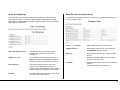
Important Safeguards
Unpacking
Remove all the items from the packaging and check you have the items listed
below.
• Dedicated Micros ATM Interface Module
• External Power Supply
• Power Leads
• Break-out Cable
• CD ROM
• Rack Mount Ears
• Installation and Setup Guide
If any of these items are missing please contact the Dedicated Micros
Technical Support team.
Important Note: Before installing the ATM Interface Module you must carefully
read all Safety Instructions and the following information on where the unit
should be located.
Safety Notes
All the safety and operating instructions should be read before the unit is
operated.
Location
Ensure the ATM Interface Module is properly ventilated to protect from
overheating.
Ensure there is a 3cm gap on both sides of the unit.
This unit must be stored in a low humidity and dust free area. Avoid places like
damp basements or dusty hallways.
Ensure the unit is not located in an area where it is likely to be subject to
mechanical shocks.
Unpacking 1
Safety Notes 1
Regulatory Notes FCC and DOC Information 2
Introduction 4
Typical System Layouts 5
Installation 6
Configuration 9
ATM Enumerate Software 15
Synopsis 17
Appendix A - Diebold 912 'Pseudo' State Codes 19
Appendix B - NCR NDC+ 'Pseudo' State Codes 19
Appendix C - Unit Specification 20
Appendix D - Break-out Cable 20
Appendix E - Ethernet Cross-over Cable 21
Appendix F - Ethernet Straight-through Cable 21
Appendix G - RS232 Serial Cable 22
1
ENGLISH

ENGLISH
2
Electrical Connections
Please ensure the following are available and have been tested prior to the
installation:
• Mains point
• Network point
• Network cable
• Desk / Laptop PC with CD ROM drive and connection to the same network
as the DV-IP
• SDLC network
WARNING: Only operate your ATM Interface Module from the type of power
source indicated on the label. Failure to do so may cause injury or death by
electric shock and invalidates the warranty.
Servicing
Do not attempt to service this unit yourself as opening or removing covers may
expose you to dangerous voltage or other hazards.
Refer all servicing to qualified service personnel.
Ventilation
Ensure unit is properly ventilated to protect from overheating as detailed
above.
WARNING: To prevent fire or shock hazard, do not expose this equipment to
rain or moisture. The lightning flash with arrowhead symbol within an
equilateral triangle is intended to alert the user of this equipment that there are
dangerous voltages within the enclosure which may be of sufficient magnitude
to constitute a risk of electric shock.
This is a class A product. In a domestic environment this product may cause
radio interference in which case the user may be required to take adequate
measures.
Lightning Strike
The ATM Interface Module has some inbuilt protection for lightning strike,
however it is recommended that isolation transformers be fitted to the system
in areas where lightning is a common occurrence.
Regulatory Notes FCC and DOC Information
(US and Canadian models Only)
Warning: This equipment has been tested and found to comply with the limits
for a Class A digital device, pursuant to part 15 of the FCC rules. These limits
are designed to provide reasonable protection against harmful interference
when the equipment is operated in a commercial environment. This equipment
generates, uses, and can radiate radio frequency energy and, if not installed
and used in accordance with the instruction manual, may cause harmful
interference to radio communications. Operation of this equipment in a
residential area is likely to cause harmful interference in which case the user
will be required to correct the interference at their own expense.
If necessary, the user should consult the dealer or an experienced
radio/television technician for corrective action. The user may find the following
booklet prepared by the Federal Communications Commission helpful: "How to
Identify and Resolve Radio-TV Interference Problems".
This booklet is available from the US Government Printing Office, Washington,
DC20402, Stock No. 004-000-00345-4.
This reminder is provided to call the CATV system installer's attention to Art.
820-40 of the NEC that provides guidelines for proper grounding and, in
particular, specifies that the cable ground shall be connected to the grounding
system of the building, as close to the point of cable entry as practical.

CE Mark
This product is marked with the CE symbol and indicates compliance with all
applicable directives.
Directive 89/336/EEC.
A "Declaration of Conformity" is held at Dedicated Micros Ltd., 11 Oak Street,
Swinton, Manchester M27 4FL.
3
ENGLISH

ENGLISH
4
Introduction
The ATM Interface Module has been designed to offer integration between
Automatic Teller Machines and the DV-IP range of video servers including the
DV-IP ATM (also includes the DM RS DVR range). The Module allows
transaction data from the ATM to be received, decoded and stored alongside
the relevant video images on the Server. A single ATM Interface Module can
support up to three ATMs.
The ATM Interface Module receives the desired data from the ATM network
infrastructure and decodes this into a format that can be interpreted by the DV-
IP ATM which then stores the text information with the corresponding video
input.
The integrated protocol conversion means the ATM Module is ideal for new or
existing installations, and by combining the video and transaction data this
Module ensures close monitoring of ATM usage is achieved. The module
directly links a single transaction with a video image and allows these to be
reviewed at a later date or used for evidence where prosecution is necessary.
The ATM Interface Module supports numerous data communication protocols
which include:
• SDLC - Synchronous Data Link Control
• HDLC - High-Level Data Link Control
• RS232
• RS422
• RS485
• SNA - System Network Architecture
It is also possible to integrate the ATM module with newer installations using IP
connectivity. In this mode the ATM Interface Module only ‘listens’ for
transaction data ensuring that the device will not impact the performance of the
banks mission critical data network.
Configuration of the unit can be via the PC application, ATM Enumerate and a
typical web browser through on-board configuration pages.
The ATM Enumerate software is supplied with the unit and allows initial
communication with the Interface Module, download or backup of set
configuration, or setting of individual parameters before integrating into the
ATM system.
The ATM Interface Module comes pre-configured with protocol conversion for
Diebold 912, Diebold XAPCOM and NCR/NDC+ protocols. Other text
mappings and translation rules may be added using the configuration screens
within the Module.
Compatible Dedicated Micros Products
There are a number of DM products that can be used in conjunction with the
ATM Interface Module, these include:
• DM's Retails Solution range of DVR's
• DM's DV-IP Server
• DM's DV-IP ATM

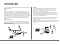
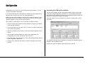
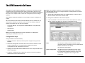
The following diagrams show typical system layouts where SDLC and Ethernet
networks are present.
SDLC
The ATM Interface Module receives the data from the SDLC network via the
serial ports by using the break out cable (supplied by Dedicated Micros, DM
part number AC-W-24951), converts this into a format that can be interpreted
by the DVR and transfers the data to the DVR via one of the other serial ports.
Note: Where the ATM is communicating with a remote Host it is recommended
that the break-out cable be connected to the modem, applications where no
modem is included the cable should be connected as close to the ATM as
possible.
Important Information
The break-out cable (Appendix D) has Transmit and Receiver data from the
SDLC network connected to the Receive data on the ATM Interface Module,
this ensures the ATM Interface Module only receives data and does not send
data back onto the network.
Typical System Layouts
5
ENGLISH
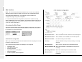
Ethernet
The ATM Interface Module receives the data directly from the Ethernet
network, via the Network port on the unit, as an IP packet this is then
translated into a format that can be transferred to the DVR. The data is
transferred via one of the serial ports on the unit.
The diagram shows how the ATM Interface Module can be connected to an
Ethernet network using a 'dumb' Ethernet Hub. An alternative connection
solution is utilising a Managed Ethernet Switch that supports a debug port, an
example of this is the Cisco
©
2900 Series.
It would be necessary to configure one of the ports for debug and enable the
transmission of UDP packets. The ATM Interface Module can then be
connected to this port.
Warning: The configuration software transmits UDP packets and therefore it is
necessary to ensure the network is configured to allow the UDP packets to be
transmitted.
1
Power
Status
Network
2
3
4
5
SDLC
RS232
DM BREAK-OUT
CABLE
ATM
ATM
ATM HOST SYSTEM
ATM
ATM
INTERFACE
MODULE
MODEM/
ROUTER
DM DVR or
DV-IP Server
VIEWING
and
CONTROL
1
Power
Power
Status
Status
Network
2
3
4
5
Ethernet
RS232
Ethernet
ATM
ATM
ATM
ATM
INTERFACE
MODULE
Ethernet Switch
Ethernet
(DUMB) Hub
DM DVR or
IP Server
ATM HOST SYSTEM

ENGLISH
6
Installing the ATM Interface Module
Network Information
The ATM Interface Module will continuously monitor the network traffic for ATM
transaction data. When utilising the network viewing capabilities of the
Dedicated Micros DVR's or DV-IP Server it is essential that the DVR/Server
and the PC receiving the video over the network are not connected to the
same Ethernet hub as the ATM Interface Module, the traffic would interfere
with the operation of the ATM Interface Module.
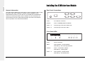
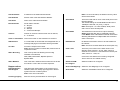
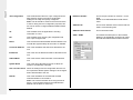
Rear Panel Connections
Power 3 Pin Mini Din connector
Network RJ45, 10/100Mbps Ethernet Network
Serial 1 - 3 9 Way D-Type Connector, RS232 only
Serial 4 - 5 9 Way D-Type Connector, SDLC
Front Panel LEDs
Power Power connected
Status Green flashing - normal operation
Red flashing - Unit receiving ATM traffic
Network Green - Connected to network
Red flashing - receiving data
Serial 1 - 5 Green flashing - Receiving data
Red flashing - Transmitting data
POWER
NETWORK
SERIAL 4
SERIAL 5
SERIAL 2
SERIAL 3
SERIAL 1
1
Power
Status
Network
2
3
4
5

Power
The Power connector is a 3 pin mini Din connector for connection to an
external power supply (supplied by Dedicated Micros).
The power requirements are 12VDC, 500mA.
Network
The Network connection is a standard RJ45 connector.
The ATM Interface Module connects to an Ethernet switch using a straight
through Cat 5 network cable (Appendix F). The Network port is 10/100Mbps
auto-detecting.
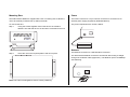
Mounting Ears
The ATM Interface Module is supplied with a set or mounting ears to allow the
unit to be vertically mounted near (or within) the ATM.
To connect the ears
Step 1 Using the screws supplied connect the ears to the Interface
Module. The side with the cut out should be connected to the unit.
Step 2 Place the unit in the required position and fix into place.
Note: The holes are elongated to ensure correct positioning.
7
ENGLISH
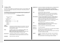
TERM
214310756 98
POWER
NETWORK
POWER
NETWORK

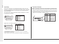
Serial Ports
There are five serial ports on the ATM Interface Module, Serial 4 and 5 are
reserved for configuration to communicate with the SDLC network. Serial ports
1 to 3 are enabled for RS232 for communication with the Dedicated Micros
DVR or DV-IP Server.
The connectors are 9 Way D-Type Male connectors. Serial ports 1 to 3 have
the following pin connections:
Serial Ports 4 and 5 have the following pin connections:
*1 the RS485/RS422 functionality is an optional item for future use, not all ATM
Interface Modules will support this.
*2 pin 8 of ports 4 and 5 is used as a synchronous clock input in certain applications.
ENGLISH
8
Termination Switches
Note: The termination switches are for future expansion. The ATM Interface
Module supports RS232 serial communication with the DVR or DV-IP Server.
There are a number of termination switches that can be found on the side of
the ATM Interface Module. These ensure that the serial ports are terminated
correctly when using RS422 or RS485 serial data.
1
6
5
9
View from the rear of the unit
Pin Pin Assignment
1
2
3
4
5
6
7
8
9
RS485 A (+)
*1
RS232 RXD
RS232 TXD
RS422 B (-)
*1
Ground
RS422 A (+)
*1
RS232 RTS
RS232 CTS
RS485 B (-)
*1
1
6
5
9
View from the rear of the unit
Pin Pin Assignment
1
2
3
4
5
6
7
8
9
RS485 A (+)
*1
RS232 RXD
RS232 TXD
RS422 B (-)
*1
Ground
RS422 A (+)
*1
RS232 RTS
RS232 RXCLK
*2
Rs485 B (-)
*1
1
ON
234
5
6
7
8910
TERM
RS485 termination
RS422 termination
RS485 termination
RS422 termination
RS485 termination
RS422 termination
RS485 termination
RS422 termination
RS485 termination
RS422 termination
Port 1
Port 1
Port 2
Port 2
Port 3
Port 3
Port 4
Port 4
Port 5
Port 5
1
2
3
4
5
6
7
8
9
10
Switch
Serial
Port
Switch Assignment

Accessing the ATM Interface Module
The first communication with the ATM Interface Module will be via the ATM
Enumerate software application (see below for a more detailed description),
this will allow the IP address of all units to be displayed and also provide the
interface to change the IP address as required.
Using the software scan for all devices connected to network (hub or cross-
over cable).
The address information will be displayed. To change the IP address edit the
address in the 'IP Address' section.
Double click on the IP address to gain web access to the unit.
Configuration of the unit can be via the ATM Enumerate Software or via the
on-board configuration web pages.
It is recommended that the configuration be carried out locally using either an
Ethernet Hub or an Ethernet cross over cable (Appendix E).
Note: The ATM Interface Module is shipped with a default IP address, if using
an Ethernet hub for communication, only connect one unit at a time until the
default IP address on each unit has been changed.
The process of configuring the units can follow this example for ease:
1. Scan the device with the ATM enumerate software; change the IP address
to the required IP address.
2. Communicate with the unit using a hub or a cross-over cable; configure the
unit using the web interface.
3. Use this configuration as the basis for other ATM Interface Modules in the
system
4. Use the ATM enumerate software to retrieve (get configuration) the
configuration file from the unit and save this to the PC
5. Download (send config) this file to any other ATM Interface Module with the
same configuration requirement
6. Change the IP addresses and make any specific changes using the web
interface
9
Configuration
ENGLISH

Send Send the configured data to the ATM Interface Module.
Show Full Account Show unmasked account details from the ATM request.
Show Part Account Show masked account details from the ATM request.
No Account Details Do not show any account details.
Currency Sets the default currency when presenting non-receipt
amounts.
Show Amounts Show currency selection and calculated amounts.
Show Transaction ID Show the transaction ID extracted from the protocol
message.
Show Keyed Amount Show the amount keyed-in from the the ATM.
Show Location Show the Unit Name and ATM Name for each
transaction.
Web Interface
Note: The PC and the ATM Interface Module must be in the same network
address range and subnet to allow access to the web configuration pages.
The ATM Interface Module can be configured via the on-board web
configuration pages using Internet Explorer.
It is recommended that the configuration of the unit be carried out locally
before installing the unit into the network. Communication between the PC and
ATM Interface Module can be achieved by using a 'dumb' hub or an Ethernet
cross-over cable (Appendix E).
Accessing the Web Pages
To access the web pages of the Interface Module, either double click on the IP
address of the unit in the ATM Enumerate software or enter the IP address in
the Address bar of Internet Explorer.
ATM Interface Configuration
When you connect to the ATM Interface Module the initial web page is the ATM
Interface Configuration page.
This configuration page allows the following to be configured:
• Transaction data
• Unit address and name
• Encoding standard
• Hoper information (money bins)
• Serial port settings
• Access to specific ATM configuration
ENGLISH
10

Unit IP Address IP address of the ATM Interface Module.
Unit Netmask Subnet mask of the ATM Interface Module.
Unit Name Name of the ATM Interface Module.
Decode Printer Printer data to decode:
0 = No print
1 = Journal
2 = Receipt
3 = Journal and Receipt.
Timeout Number of seconds until the screen text is cleared;
0 = no timeout.
Clear on Transaction Clear screen when a new transaction is received.
ATM Timeout If no ATM traffic is sensed after this designated time, a
message relaying this information will be generated.
Tx UTF8 Format the output text as UTF8.
Note: this has no effect on ASCII data, however this is
required for Arabic.
SDLC Encoding This is a drop down list allowing the encoding
standard to be selected;
NRZ, NRZI, Manchester, Biphase Space or
Biphase Mark
SDLC Modulus This is the SDLC address filed format and must be left
as modulo 8. This is also for future expansion.
Hopper values
Diebold Hoppers This allows the denomination of each hopper to be
NCR Hoppers identified, there are usually eight hoppers in diebold
systems and four in NCR systems.
Note: Coins are not decoded.
Currency [hopper] Sets the currency demonination for each hopper.
11
ENGLISH
Note: If a box is left blank, the default Currency value
will be used instead.
Serial Baud This is the baud rate for each of the serial ports on the
Interface Module.
The default settings of the DM DVRs and DV-IP are:
19200bps 8 data bits, nor parity, 1 stop bit.
Note: Serial ports 1 to 3 are enabled, serial ports 4
and 5 are for future development.
Serial Mode This determines how the text is output. Selecting
Simple generates text with no additional protocols,
unlike MuxK which adds additional header information.
Selecting MuxK allows multiple ATMs and cameras to
share a serial port.
DVR Address IP address of the DVR if text is to be transmitted via
the network.
Note: The DV-IP receives data via the serial ports only.
Cam 1 Port This is the port number for the base camera. The
diagram shows camera 1 as port 1500, camera 2
would be a increment of 1 and therefore would be port
1502, camera 3 - 1503, etc.
Commit Commit the sent data to the unit being configured.
This is stored in non-volatile memory.
Select the ATM Allows an ATM to be configured.
to Configure
Show Text Mappings Allows the Text Mappings to be configured.
Show Rules Allows the Translatation Rules to be configured.

ATM Address This is the IP address of the ATM machine. The ATM Interface
Module only monitors traffic between the designated IP
address of the host and ATM machine.This means that all
external interfaces and equipment, except that of the host and
ATM, are ignored.
Port This is the port number of the ATM.
Note: Recommended this is left at 0 to ensure all traffic is
monitored regardless of the port number. If the ATM resets
the port number can change after initialisation.
Host Address This is the network address of the host computer system. It
is usually the format that the ATMs will communicate with a
single host, however this option allows any host to be
configured where multiple hosts are connected in the system.
Note: Leaving this blank will result in no traffic being
monitored to the host.
Port This identifies the port number to be monitored.
Note: Recommended this is left at 0 to ensure all traffic is
monitored regardless of the port number.
Camera 1 Primary camera on the DVR allocated to this ATM.
Camera 2 For future expansion.
Serial O/P Identifies which of the serial ports on the ATM Interface Module
will send data to the DVR or DV-IP Server.
Note: Setting this to 0 will switch off serial output and therefore
not send any data to the DVR.
Update Send the configuration within this page to the ATM Interface
Module.
Note: To commit this information to the non-volatile memory
the Commit button on the main page must be selected.
Configure ATM
The ATM Interface Module can simultaneously support up to three ATM's. Each
ATM can be individually configured by selecting the corresponding ATM from
the drop down list.
The relevant information on the ATM is configured within this web page to allow
communication to be established. This also links an ATM to a specific serial
port on the ATM Interface Module.
ATM Type This allows the relevant ATM type to be selected. The ATM
Interface Module currently supports Diebold 912, Diebold
XAPCOMand NCR NDC+.
Drop The SDLC network can be configured as multidrop. This
allows the devices to be correctly addressed.
Note: If Diebold XAPCOM is selected, the serial port that
receives the data will register as the Drop value.
Data Format This allows the data format to be configured. The ATM
Interface Module currently supports SNA, X25 and TCPIP.
ATM Name This is the name of the ATM.
ENGLISH
12

Show Receipt Translation Rules
This allows the translation rules to be configured. It is possible to configure up
to forty translation rules.
"<9-16>" -> "<33-40>" Select alternative set of 8 rules to edit.
"Update<nn-nn>" Send values entered to the unit. Press this
key BEFORE changing screen.
Rule (nn) Drop down list selects type of rule (see table
above).
Subsequent 2 boxes allow entry of required
strings for each rule type.
"Commit" Commit values sent to the unit to non-volatile
memory.
Commits all values from all screens.
Show Text Mappings
This allows the text transaction settings to be configured. These settings
should be configured in conjunction with Appendix A Diebold 912 'Pseudo'
State Codes and Appendix B NCR NDC+ 'Pseudo' State Codes. For Diebold
XAPCOM, use Appendix A.
User Text String <nn-nn> This allows a set of 6 text strings to be
selected. Up to 60 text strings can be
configured.
Update <nn - nn> This sends the values entered to the unit.
Note: Press this button BEFORE changing
screens to ensure the information is saved.
User String (n) The first box allows the user text to be
entered. The subsequent boxes all for
mapping of the ATM states and pseudo states.
Refer to Appendix A and B for more details.
Commit This will commit the values sent to the unit to
the units non-volatile memory.
13
ENGLISH

The translation formats are:
TRANSLATE
If ESC&String1 are detected in text initiate translation of subsequent text.
SUBSTITUTE_STRING
If String 1 is detected in text line swap it for string 2.
SUBSTITUTE_STRING_PRINT_NEXT
If String 1 is detected in text line swap it for string 2 and always print next line
as is.
SUBSTITUTE_LINE
If String 1 is detected in text line swap entire line for string 2.
SUBSTITUTE_LINE_PRINT_NEXT
If String 1 is detected in text line swap entire line for string 2 and always print
next line as is.
MASK_LINE
If String 1 is detected in text line do not print the line.
MASK_CURRENCY
If String 1 is detected in text line mask all currency values in that line.
MASK_ALL_CURRENCY
If String 1 is detected anywhere in text mask all currency values in the entire
print text.
MASK_FIRST_CURRENCY
If String 1 is detected anywhere in text mask first currency values in each line
of the print text.
MASK_LAST_CURRENCY
If String 1 is detected anywhere in text mask last currency values in each line
of the print text.
ENGLISH
14
OP_CODE
When a transaction is requested at an ATM, a request is sent from the ATM to
the Host. This request is made up of several parts; one of them being the
OP-CODE which provides information to the acquiring host about the type of
transaction requested.
In the above example (where ‘*’ can be any character), ‘C*******’ will interpret
any OP_CODE beginning with ‘C’ as a ‘Balance Enquiry’. The ‘********’
represents a catch-all, so anything not beginning with a ‘C’ will be caught by
this and represented as a ‘Transaction Request’. If a rule has been set in the
ATM Interface to detect an OP_CODE, the OP_CODE will be decoded and
presented. If no rule has been set to detect the OP_CODE, no data will be
generated.

Note: It is possible to select the 'Use overrides below' option. This allows
individual ATM settings to be configured where the settings differ from that of
the configuration.ini file.
5. The file will be downloaded to the non-volatile memory of the unit. Once
the file has been sent to the unit it will reset.
6. Change the IP address of the unit as required.
7. It is then possible to connect to the unit via the web interface to make any
specific changes that differ from that of the configuration.ini file.
Scan This will send a UDP packet across the network
requesting specific information from any ATM Interface
Module connected to the network.
The UDP Port used is 8230.
Send Configuration This allows a saved configuration file (from a pre-
configured unit) to be sent to different units where
the configuration requirements are the same. This
reduces the configuration time in larger scale
installations
The ATM Enumerate Software application is provided on a CD with the ATM
Interface Module, this software allows initial communication with the unit to
configure the IP address of the unit. It also allows a saved default configuration
file to be sent to multiple units to reduce the configuration process in larger
systems.
This software should be installed on a PC that will be used to configure the
system.
When the software is launched it will automatically scan the network for any
ATM Interface Modules connected to the network. The software requests
specific information from the units, this includes:
• Current IP address - this may be the default address or one previously
configured
• Subnet mask
• System name
Note: The message transmitted from the application is a UDP packet
requesting IP information on the unit.
Configuration Steps
Using the ATM enumerate software;
1. Highlight the device that has previously been configured using the web
interface.
2. Select Get Configuration and save this on the local PC hard drive, name
the file configuration.ini. The ATM Interface Module will create a
configuration file and download this to the PC.
3. Highlight the next ATM Interface Module that is to be configured and Select
Send Configuration.
4. Locate the configuration.ini file previously saved you will be prompted to
check the file is to be sent to the unit.
15
The ATM Enumerate Software
ENGLISH

DVR Port Number This is the port number for Camera 1 on the
DVR.
Default for a Dedicated Micros DS2 DVR is
7000
ATM Host IP This is the IP address of the Host PC that the
ATM is communicating with
ATM Host Port Number This must remain blank
ATM1 - ATM4 This allows the serial ports on the Interface
Module to be individually configured to reflect
the ATM associated with that serial interface
Get Configuration This will download a file from a pre-configured unit to
allow devices requiring the same configuration
settings to be easily and quickly configured
Note: The file should be saved to the local hard drive
of the PC being used for configuration purposes, this
file can be used to configure additional ATM Interface
Module
TX This will flash when the application is sending
information to a unit
RX This will flash when receiving the configuration file
from a pre-configured unit
Reset This will reset the selected ATM Interface Module. The
unit will take approximately 30 seconds to re-initialise.
Current IP Address This is the IP address that has been allocated to the
unit.
IP Address This is the new IP address that will be allocated to the
unit
Subnet Mask This is the subnet mask information of the selected
unit
System Name This is the name allocated to the unit to allow the
system to be efficiently managed
Use overrides below When the settings with the configuration files are not
as required this allows specific settings to be changed
before downloaded to the unit
DVR IP This is the IP address of the DVR that the ATM
Interface Module is connected to
Note: This must be left blank when using the DV-IP
Server, communication between the ATM Interface
Module and the DV-IP is serial only
ENGLISH
16

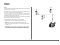
SDLC
Synchronous Data Link Control developed by IBM
®
for use in System Network
Architecture (SNA) environments.
SDLC protocol sits at the link layer of the OSI model and is bit-oriented. There
are two types of network nodes; Primary and Secondary.
The Primary node takes control of the other stations, in an ATM application the
mainframe computer at a central location would be the primary node with the
ATM machines would be the secondary nodes.
The mainframe will poll each ATM machine and all transactions from the ATM
machine would be transmitted to the mainframe.
The nodes connection topology can be one of the following:
• Point to point - involves one primary and one secondary only
• Multipoint - involves one primary and multiple secondary nodes
• Loops - this is a loop where the primary is connected to the first and last
secondary node
• Hub go-ahead - This has an inbound and outbound channel. The primary
communicates on the outbound to the secondary nodes; the secondary
nodes use the inbound channel to communicate with the primary node
17
Synopsis
ENGLISH
SDLC
ATM
ATM
MAINFRAME
ATM

RS232
RS232 is a universal data interface. RS232 is a point-to-point electrical data
communication and is commonly integrated in both network and CCTV
products.
Independent channels are available for two-way communication (i.e. full
duplex). The RS232 signals are identified by voltage levels.
As this is a universal data interface the pin connections are standard and
ensure that the data is transmitted and received correctly between devices.
The characteristics of RS232 are:
• Point to point (Single ended) - communication is between two devices
• Speeds are usually up to 256kbps
• Maximum distance between the devices is 15 Metres
HDLC
High-Level Data Link Control is a derivative of the SDLC and sits at Layer 2
(Data link) of the OSI model.
The HDLC protocol can be use in both point-to-point and multipoint data links.
There are three modes of operation:
• Normal Response Mode (NRM) - In this mode of operation the secondary
device are not able to communicate with the primary until permission has
been granted by the primary node. This mode is also used by SDLC.
• Asynchronous Response Mode (ARM) - This mode allows secondary
nodes to initiate communication with the primary node without requesting
and receiving permission from the primary node.
• Asynchronous Balanced Mode (ABM) - This mode introduces the
combined node which can act as a primary or secondary node depending
on the situation.
The two basic functions in HDLC protocol are link management and data
transfer.
Link Management
Prior to any information being transmitted (either as point-to-point or multipoint)
a connection must be established between the devices to allow
communication.
Data Transfer
The data transfer is monitored and includes error control and flow control.
ENGLISH
18
Page is loading ...
Page is loading ...
Page is loading ...
Page is loading ...
Page is loading ...
Page is loading ...
-
 1
1
-
 2
2
-
 3
3
-
 4
4
-
 5
5
-
 6
6
-
 7
7
-
 8
8
-
 9
9
-
 10
10
-
 11
11
-
 12
12
-
 13
13
-
 14
14
-
 15
15
-
 16
16
-
 17
17
-
 18
18
-
 19
19
-
 20
20
-
 21
21
-
 22
22
-
 23
23
-
 24
24
-
 25
25
-
 26
26


Dedicated Micros ATM Interface Module Owner's manual
- Category
- Networking
- Type
- Owner's manual
Ask a question and I''ll find the answer in the document
Finding information in a document is now easier with AI
Related papers
-
Dedicated Micros DV-IP ATM Installation guide
-
-
-
-
-
-
 Code Alarm 485-bus Alarm Module (CI01) User guide
-

Other documents
-
 Triton Systems FT7000XP Series Owner's manual
-
 Elen NDC 57/4 R L20 User manual
-
Bull AIX 4.3 - Communications Programming Guide
-
 Triton Systems RL5000XP Series Owner's manual
-
-
-
 Eusso UNC7825 Series Owner's manual
-
 Triton Systems RL5000XP Series Owner's manual
-
Avaya 1D5 Release Notes
-
AVE Video Serial Synchronous ATM Interface VSSI-PRO User manual


