SureCall SC-POLYSH/O-72-OD-KIT User guide
- Type
- User guide
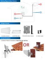
SureCall SC-POLYSH/O-72-OD-KIT is a powerful signal booster kit designed to eliminate dropped calls, slow data speeds, and improve overall cellular reception in homes up to 6,000 square feet. With its ability to enhance signals for multiple carriers and devices simultaneously, this kit is ideal for boosting 2G, 3G, and 4G voice and data signals. The kit includes an outdoor omni antenna for capturing weak signals and an indoor dome antenna for distributing boosted signals throughout your home. Installation is simple and straightforward, with clear instructions provided in the user guide.
SureCall SC-POLYSH/O-72-OD-KIT is a powerful signal booster kit designed to eliminate dropped calls, slow data speeds, and improve overall cellular reception in homes up to 6,000 square feet. With its ability to enhance signals for multiple carriers and devices simultaneously, this kit is ideal for boosting 2G, 3G, and 4G voice and data signals. The kit includes an outdoor omni antenna for capturing weak signals and an indoor dome antenna for distributing boosted signals throughout your home. Installation is simple and straightforward, with clear instructions provided in the user guide.


-
 1
1
-
 2
2
-
 3
3
-
 4
4
-
 5
5
-
 6
6
-
 7
7
-
 8
8
-
 9
9
-
 10
10


SureCall SC-POLYSH/O-72-OD-KIT User guide
- Type
- User guide
SureCall SC-POLYSH/O-72-OD-KIT is a powerful signal booster kit designed to eliminate dropped calls, slow data speeds, and improve overall cellular reception in homes up to 6,000 square feet. With its ability to enhance signals for multiple carriers and devices simultaneously, this kit is ideal for boosting 2G, 3G, and 4G voice and data signals. The kit includes an outdoor omni antenna for capturing weak signals and an indoor dome antenna for distributing boosted signals throughout your home. Installation is simple and straightforward, with clear instructions provided in the user guide.
Ask a question and I''ll find the answer in the document
Finding information in a document is now easier with AI
Related papers
-
SureCall SC-Fusion5X2-OD User guide
-
SureCall SC-Fusion5X2-OD User manual
-
SureCall 5X Max User guide
-
-
SureCall SC-FlareDB User guide
-
SureCall FusionProfessional Cellular signal booster kit for the Home or Office User manual
-
-
SureCall Fusion4Home User manual
-
-
Other documents
-
AT&T Cell Phone Booster Installation guide
-
DeLOCK 46273 Datasheet
-
APPS SureCall Operating instructions
-
HiBoost HiBoost 3-Band Cell Phone Signal Booster Up to 1,000 sq ft for Home & Office,Boosts Band 12/17/13/5, 3G 4G LTE Voice and Data for Verizon,T-Mobile, AT&T,Cellular Repeater Amplifier Kits Installation guide
-
 Amazboost Amazboost Cell Phone Signal Booster Kit,All U.S. Carriers -Verizon,AT&T, T-Mobile, Sprint, U. S. Cellular-Cell Phone Booster Max 2,500 sq ft,Cell Signal Amplifier FCC Approved, 4g s2 Installation guide
-
 Phonetone PTE-C980D User manual
-
Shakespeare Electronic superhalo CA-VAT-10-R User manual
-
-
Potter Guardian3 QR User manual
-
 SolidRF BuildingPro 5 User manual


