Page is loading ...

Flare
™
/ Flare-C
™
User Guide
Cellular signal booster kit with combined
booster and indoor antenna
• Flare Omni kit for voice & 4G data (US)
• Flare Yagi kit for voice & 4G data (CANADA)
• Flare-C Yagi kit for voice & text signal (CANADA)

SureCall | 48346 Milmont Drive, Fremont CA 94538 | 1-888-365-6283 | [email protected]
Introduction
2
Thank you for purchasing SureCall’s Flare cellular signal booster kit. SureCall’s Flare was specically designed to
eliminate frustrations over dropped calls and limited range by amplifying incoming and outgoing cellular signals in
homes and oces.
If you have any questions during setup, please reach out to our US-based experienced support technicians:
Call: 1-888-365-6283
Email: [email protected]
Or, chat: www.surecall.com, 7:00 am – 5:00 pm PST, Monday – Friday
Watch installation,
optimization and
troubleshooting
techniques on our
SureCall YouTube
channel
@SureCall
Stay up to date
with all things
SureCall

SureCall | 48346 Milmont Drive, Fremont CA 94538 | 1-888-365-6283 | [email protected]
Table of Contents
TABLE OF CONTENTS
How it works .................................................................................................................................... 4
PACKAGE CONTENTS ........................................................................................................................ 5
BEFORE INSTALLATION ..................................................................................................................... 6
Installation Overview ........................................................................................................................ 6
FLARE INSTALLATION ........................................................................................................................ 6
Step 1. Find the Area With the Strongest Signal ............................................................................ 6
Step 2. Install the Outside Antenna ................................................................................................. 7
Step 3. Place the Booster ............................................................................................................... 9
Step 4: Connect to Power ............................................................................................................... 9
Step 5: Enjoy Boosted Signal .......................................................................................................... 9
IF YOU WANT TO IMPROVE PERFORMANCE ................................................................................ 10
LED INDICATORS .............................................................................................................................. 10
TROUBLESHOOTING ........................................................................................................................ 10
FLARE SPECIFICATIONS .................................................................................................................. 11
Kitting Information ......................................................................................................................... 12
FCC & IC INFORMATION ................................................................................................................... 14
WARRANTY ....................................................................................................................................... 15
Three-Year Product Warranty ........................................................................................................ 15
Limitations of Warranty, Damages and Liability ........................................................................... 15
3

SureCall | 48346 Milmont Drive, Fremont CA 94538 | 1-888-365-6283 | [email protected]
4
How It Works
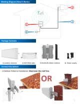
How it works
1. An outside antenna collects signal from the cell tower.
2. The outside antenna sends the signal to the booster through coax cable.
3. The booster amplies the cell signal and rebroadcasts the signal indoors to all mobile devices within range.
4. The booster amplies outgoing cell signal back to the tower.
min
i
mum 25
ft.
sepa
r
ation
Cable
Power Supply
Booster
Outside Omni Antenna (a)
Outside Yagi Antenna (b)
How the SureCall Flare Booster Works

SureCall | 48346 Milmont Drive, Fremont CA 94538 | 1-888-365-6283 | [email protected]
5
Package Contents
Warning: Unauthorized antennas, cables, and/or coupling devices are prohibited by FCC new rules. Please contact FCC for details: 1-888-CALL-FCC.
Changes or modications not expressly approved by SureCall could void the user’s authority to operate the equipment.
1. Flare Cellular Booster 3. Indoor Cable (50 ft.)
4. Outside Antenna Options:
PACKAGE CONTENTS
Unpack all package contents. For missing or damaged items, contact your reseller.
Turn over the signal booster and record the model and serial number for reference:
Serial #: ________________________________________________________________#
Purchase Date: __________________________________________________________
Keep the carton and packing material to store the product in case you need to return. Your Flare signal booster
package includes the following items:
1. SureCall Flare signal booster
2. Power supply
3. Cable for connecting the outside antenna to the signal booster
4. One outside antenna (either omni or Yagi antenna)
2. Power Supply
4b. Outside Yagi Antenna 4a. Outside Omni Antenna OR

SureCall | 48346 Milmont Drive, Fremont CA 94538 | 1-888-365-6283 | [email protected]
6
BEFORE INSTALLATION
1. Prior to securing the location of any booster parts, a “soft install” is recommended as adjustments may be
needed to optimize performance.
2. Your planned location for the booster (central to where signal is needed) should be near an existing electrical outlet.
3. Ensure adequate separation between the planned locations of the booster and outside antenna (at least 30 ft.).
4. Ensure sucient cable length between the outside antenna location and booster location. The length of the
provided cable is 50 ft.
Installation Overview
Step 1. Find the outside area with the strongest signal.
Step 2. Install the outside antenna
Step 3. Place the Flare on a table or desktop, center of the area where signal is needed.
Step 4. Connect the booster to an AC power source.
FLARE INSTALLATION
Step 1. Find the Area With the Strongest Signal
Finding Your Strongest Cellular Signal
Using your phone, identify the outside location with the strongest signal. Generally, this is found on the side facing
your nearest cell tower and as high as possible.
For specic dB signal measurements, use the methods below. Note that dB measurements appear as a negative
number where the closer to 0, the stronger the signal (eg. -100 dB would be considered a weak signal while -65 dB
a strong signal).
• Apple iPhones: Dial *3001#12345#* and press Call. In the top-left corner, a dB number appears instead of
bars.
• Android devices:
download the app
“Network Signal Info” in
the Google Play store.
Note that Bars are not always
a reliable measure of signal.
The best way to conrm
signal coverage is the ability
to place and hold a call.
Before Installation
Signal Strength
Excellent
-50 dB
-60 dB
-70 dB
-80 dB
-90 dB
-100 dB
GoodPoor

SureCall | 48346 Milmont Drive, Fremont CA 94538 | 1-888-365-6283 | [email protected]
7
Step 2. Install the Outside Antenna
After identifying the area of strongest signal, choose the surface where you will mount the outside antenna.
Using the provided hardware, mount the outside antenna at the highest possible elevation, allowing a minimum
separation of 25 feet from the planned location of the booster.
Once the outside antenna is secured, connect one end of the provided cable to the outside antenna and tighten the
connection.
Do not collocate antennas or operate the outdoor antenna with any other antenna or signal booster.
Option A: Omni Antenna
The omni antenna is omni-directional, which receives and sends signals in a 360º radius.
The provided hardware allow for either a surface mount or pole-mount.
Mount antenna to a vertical surface:
1. Using vertical plate of bracket, mark position of desired placement. The omni
antenna should be mounted in an upright position (See “Omni Outside Antenna Install
Illustration” on page 7)
2. Unscrew nut from end of stucco screw and remove it along with lock washer and
regular washer.
3. Place vertical plate into desired location and tap the screws, head rst, along with
sleeve, into stucco 1/2 to 5/8 inches deep into place.
4. In this order, place washer, lock washer and nut on each screw and tighten until
secure. When tightening screw, sleeve will expand to secure plate.
5. Remove screws from antenna base and use to secure antenna onto horizontal plate.
6. Connect antenna to one end of the provided RG6 cable and tighten the connection. Run the cable along route
to planned location of your booster.
Note: Alternate screws may be required for diering surfaces such as wood or concrete.
Installation
Pole-mount hardware
Omni antenna with
surface mount hardware
Cable
Planned
Booster
Location
Outside
Antenna
min
i
mum
2
5 f
t.
sep
a
rat
i
o
n
Nuts &
Washers
L-Bracket
Cable
Anchors /
Sleeves
Screws
Omni Outside Antenna Install Illustration

SureCall | 48346 Milmont Drive, Fremont CA 94538 | 1-888-365-6283 | [email protected]
8
Option B: Outside Yagi Antenna
Before installing a Yagi, or directional antenna, note that the antenna
should be mounted on a pole or pipe (not provided), at the highest possible
location and mounted horizontally, aimed in the direction of your nearest
cell tower. To nd the location of your carrier’s closest cell tower, go to
www.antennasearch.com.
Ensure that the mounting area has at least a 12-inch radius clear of
obstructions and other radiating elements and orient the antenna with the
drip hole at the bottom.
Once you have identied your install location, assemble the u-bolt, bracket,
nuts and washers onto a pole or pipe (not provided) as shown in the
illustration. Keep the connections loose enough to allow the antenna to
rotate until the optimum direction is found.
Once the outside antenna is secured to a pipe or pole, connect antenna
to one end of the provided RG6 cable and tighten the connection. Run the
cable along route to planned location of your booster.
Installation
Outside Antenna Assembly
Nut
Washer
U-bolt
Bracket
Drip Hole
RG6 Cable
Cable
Planned
Booster
Location
Outside
Antenna
min
i
mum
2
5 f
t.
sep
a
rat
i
o
n
Omni Yagi Antenna Install Illustration

SureCall | 48346 Milmont Drive, Fremont CA 94538 | 1-888-365-6283 | [email protected]
9
Installation
Step 3. Place the Booster
Place the booster in a central location where signal is needed and at least 25 ft. from the outdoor antenna location.
When placing the booster, note that further separation between the booster and outside antenna will increase
booster performance. Connect the open end of the RG6 cable from the outside antenna to the booster and tighten
connection.
Please note that the performance and range of your
booster depends on three factors:
1. Signal strength at the location of the outside antenna.
2. Interior building materials between the booster and
your mobile device.
3. Distance between the outside antenna and booster
(while at least 25 ft. separation is recommended,
further separation will increase performance).
Note: Fixed stations operating in the 1710-1755 MHz bands are limited
to a maximum antenna height of 10 meters above ground.
This booster should not be used near open re or ame. Storage
and transportation: Store and place in non-extreme room-
temperature and dry environment.
Step 4: Connect to Power
Once the booster and outside antenna are connected
and in place, connect the power cord to the signal
booster and plug into a power outlet.
Note: This booster is rated for 5-15V input voltage. DO NOT use the
booster with a higher voltage power supply. This can damage
the booster, cause personal injury, and void your warranty.
Step 5: Enjoy Boosted Signal
Place a call in the room where the booster is located to
conrm that your phone is receiving a boosted signal.
Remember: Bars are not always a reliable measure of
signal. The best way to conrm signal coverage is the
ability to place and hold a call.
Placing Booster and connecting cable
Connecting the Power Supply

SureCall | 48346 Milmont Drive, Fremont CA 94538 | 1-888-365-6283 | [email protected]
10
IF YOU WANT TO IMPROVE PERFORMANCE
• Identify a location outside that receives a stronger signal and move the outside antenna to that location (higher
is usually better.
• Increase the distance between the booster and outside antenna.
• If using an omni outside antenna, upgrade to a directional yagi antenna that can be aimed toward your closest
tower.
Please Note: Changes or modications not expressly approved by SureCall could void user’s authority to operate the equipment.
LED INDICATORS
LED
Position
LED
Color
LED
Condition
Indication
Left Yellow Flashing Automatic Gain Control (AGC) is self-adjusting. This is part of normal operation.
Right Yellow Flashing Automatic Gain Control (AGC) is preventing oscillation.
If this happens: Increase separation between outside antenna and booster to optimize
performance.
Left Red Flashing The booster is receiving too strong of a signal which could cause the booster to automatically
turn o.
If this happens, relocate the outside antenna to a location where the signal is weaker. If using a
Yagi outside antenna, turn in small increments away from cell tower until Red ashing stops.
Right Red /
Yellow
Alternately
Flashing
Booster function has shut o to prevent oscillation.
If this happens: Increased separation between the outside antenna and Flare booster is needed to
continue proper operation.
Booster LED Diagram
Left LED
Right LED
Power LED
TROUBLESHOOTING
If you have any questions during setup, please reach out to our US-based experienced support technicians:
Call: 1-888-365-6283
LED Indicators & Troubleshooting

SureCall | 48346 Milmont Drive, Fremont CA 94538 | 1-888-365-6283 | [email protected]
11
Specications
Email: [email protected]
Or, chat: www.surecall.com, 7:00 AM – 5:00 PM PST, Monday – Friday
Problem Resolution
Signal booster has no power Connect the power supply to an alternate power source.
Be sure the power source is not controlled by a switch that can remove power from the outlet.
Check the POWER LED () on the signal booster. If it is OFF, return the power supply to SureCall. Contact
tech support at to receive an RMA at:
Friday to chat with a representative.
After installing your signal
booster system, you have no
signal or reception
Verify that cable connections are tightly tted to the booster and antenna.
Try further separating the booster and antenna.
Verify that there is usable signal where the antenna is placed.
Remember: Bars are not always a reliable measure of signal. The best way to conrm signal coverage is
the ability to place and hold a call.
FLARE SPECIFICATIONS
U.S. Canada
5-Band Kit with Omni
(SC-Poly-DT-O-Kit)
5-Band Kit with Yagi
(SC-Poly-DT-CA)
Dual Band Kit with Yagi
(SC-Dual-DT-Y-CA)
Uplink Frequency Range (MHz): 698-716 / 776 – 787 / 824-849 / 1850-1915 / 1710-1755 824-849 / 1850-1915
Downlink Frequency Range (MHz):
728-746 / 746 – 757 / 869-894 / 1930-1995 / 2110-2155 869-894 / 1930-1995
Donor/Server Port Impedance: 75 ohm / 50 ohm
Maximum Gain: 72 dB 75.1 dB 78.9 dB
Noise Figure: 7 dB
VSWR: ≤2.0
Supported Standards: CDMA, WCDMA, GSM, EDGE, HSPA+, EVDO 4G and all cellular
standards
CDMA, WCDMA, GSM, EDGE,
HSPA+, EVDO
AC Input: Input: AC 110 – 240 V, 60 Hz ; Output: DC 5V / 3A
Maximum Output Power: 1 Watt EIRP 3 Watt EIRP
Cable: RG6 (50 ft.)
RF Connectors: Donor port: F Female, Server port: Integral
Power Consumption: <12W
Weight: 1. 8125 lb.
Dimensions: 5.125 × 7.25 × 5.625 inches
FCC ID / IC: RSNDT 7784A-FLARE 7784A-FLAREDB
Max Coverage Area: 2,500 Sq. Ft. 3,000 Sq. Ft.

SureCall | 48346 Milmont Drive, Fremont CA 94538 | 1-888-365-6283 | [email protected]
12
Kitting Information
Flare 5-Band Kit with Omni (US): SC-Poly-DT-O-Kit
Flare 5-Band Kit with Yagi (Canada): SC-Poly-DT-CA
Component Product number Gain/Loss Note
LTE-A
707 MHz
LTE-V
731 MHz
Cellular
800 MHz
PCS
1900 MHz
AWS
1700 / 2100 MHz
Outdoor Antenna* SC-289W 3 dBi 3 dBi 3 dBi 4 dBi 4 dBi / 4 dBi
SC-231W 10 dBi 10 dBi 10 dBi 10 dBi 10 dBi / 10 dBi
Outdoor Cable* SC-RG6-50 3.32 dB 3.32 dB 3.75 dB 6.42 dB 6.22 dB / 6.68 dB 50 Feet or longer
Indoor Antenna SC-322W 2.5 dBi 2.5 dBi 3 dBi 5 dBi 4 dBi / 5 dBi
SC-302W 2.5 dBi 2.5 dBi 3 dBi 5 dBi 4 dBi / 5 dBi
* The Flare booster is suitable for use with all equivalent and lower gain antennas, as well as, equivalent or greater lengths of cable.
Frequency (MHz) Bandwidth (MHz) Input (dBm) Mean Power (dBm) Gain (dB)
Uplink: 1710-1755 75.0 -49.4 24.3 73.7
Uplink: 1850-1915 75.3 -49.8 21.7 71.5
Uplink: 824-849 36.3 -43.6 20.6 64.2
Uplink: 698-716 23.8 -40.1* 23.2 63.3
Uplink: 777-787 24.0 -45.9* 18.3 64.2
Downlink: 2110-2155 86.5 -54.7* 20.4 75.1
Downlink: 1930-1995 74.4 -52.3* 22.0 74.3
Downlink: 869-894 36.3 -36.7 20.8 57.5
Downlink: 728-746 33.8 -37.7 19.4 57.2
Downlink: 746-756 33.9 -32.8 19.8 52.6
*Mean power: Measurements obtained on section 6.2 where Pmean = P01+3dB
Flare Dual Band Kit with Yagi (Canada): SC-Dual-DT-Y-CA-Kit
Component Product number Gain/Loss Note
Cellular - 800 MHz PCS - 1900 MHz
Outdoor Antenna* SC-289W 3 dBi 4 dBi
SC-231W 10 dBi 10 dBi
Outdoor Cable* SC-RG6-50 3.75 dB 6.42 dB 50 Feet or longer
Indoor Antenna SC-322W 3 dBi 5 dBi
SC-302W 3 dBi 5 dBi
* The Flare booster is suitable for use with all equivalent and lower gain antennas, as well as, equivalent or greater lengths of cable.
Kitting

SureCall | 48346 Milmont Drive, Fremont CA 94538 | 1-888-365-6283 | [email protected]
13
Kitting
Kitting
Frequency (MHz) Bandwidth (MHz) Input (dBm) Mean Power (dBm) Gain (dB)
Uplink: 1850-1915 75.0 -56.9* 22.0 78.9
Uplink: 824-849 36.8 -48.7 20.9 69.6
Downlink: 1930-1995 75.3 -45.6 21.0 66.6
Downlink: 869-894 36.5 -39.2 19.8 59.0
*Input power level is decreased before reaching AGC -0.5 dB to maintain compliance with the intermodulation product of -13 dBm.
Mean power: Measurements obtained on section 6.2 where Pmean = P01+3 dB

SureCall | 48346 Milmont Drive, Fremont CA 94538 | 1-888-365-6283 | [email protected]
14
FCC & IC INFORMATION
Important: Before installing your booster you need to register it with your carrier. You can do so online at the following urls:
Verizon: http://www.verizonwireless.com/wcms/consumer/register-signal-booster.html
AT&T: https://securec45.securewebsession.com/attsignalbooster.com/
T-Mobile: https://support.t-mobile.com/docs/DOC-9827
Sprint: https://www.sprint.com/legal/fcc_boosters.html
U.S. Cellular: http://www.uscellular.com/uscellular/support/fcc-booster-registration.jsp
FCC Information:
This is a CONSUMER device.
BEFORE USE, you MUST REGISTER THIS DEVICE with your wireless provider and have your provider’s consent. Most wireless providers consent to
the use of signal boosters. Some providers may not consent to the use of this device on their network. If you are unsure, contact your provider.
You MUST operate this device with approved antennas and cables as specied by the manufacturer. Antennas MUST be installed at least 20 cm (8
inches) from any person. You MUST cease operating this device immediately if requested by the FCC or a licensed wireless service provider.
This device may be operated ONLY in a xed location for in-building use.
WARNING: E911 location information may not be provided or may be inaccurate for calls served BY USING THIS DEVICE.
Note: This equipment has been tested and found to comply with the limits for a Class B digital device, pursuant to part 15 of the FCC Rules. These
limits are designed to provide reasonable protection against harmful interference in a residential installation. This equipment generates, uses and
can radiate radio frequency energy and, if not installed and used in accordance with the instructions, may cause harmful interference to radio
communications. However, there is no guarantee that interference will not occur in a particular installation. If this equipment does cause harmful
interference to radio or television reception, which can be determined by turning the equipment off and on, the user is encouraged to try to correct the
interference by one or more of the following measures:
• Reorient or relocate the receiving antenna
• Increase the separation between the equipment and receiver.
• Connect the equipment into an outlet on a circuit different from that to which the receiver is connected
• Consult the dealer or an experienced radio/TV technician for help.
Industry Canada:
This Class B digital apparatus meets all requirements of the Canadian Interference Causing Equipment Regulations. Operation is subject to the
following two conditions: (1) this device may not cause harmful interference, and (2) this device must accept any interference received, including
interference that may cause undesired operation
Cet appareillage numérique de la classe B répond a toutes les exigencies de l’interférence canadienne causant des réglements d’équipment.
L’opération est sujette aux deux conditions suivantes: (1) ce dispositif peut ne pas causer l’interférence nocive, et (2) ce dispositif doit accepter
n’importe quelle intérference reçue, y compris l’intérference qui peut causer l’opération peu désirée.
The Manufacturer’s rated output power of this equipment is for single carrier operation. For situations when multiple carrier signals are present, the
rating would have to be reduced by 3.5 dB, especially where the output signal is re-radiated and can cause interference to adjacent band users. This
power reduction is to be by means of input power or gain reduction and not by an attenuator at the output of the device.
La puissance de sortie nominale indiquée par le fabricant pour cet appareil concerne son fonctionnement avec porteuse unique. Pour des appareils
avec porteuses multiples, on doit réduire la valeur nominale de 3,5 dB, surtout si le signal de sortie est retransmis et qu’il peut causer du brouillage
aux utilisateurs de bandes adjacentes. Une telle réduction doit porter sur la puissance d’entrée ou sur le gain, et ne doit pas se faire au moyen d’un
atténuateur raccordé à la sortie du dispositif
FCC, IC & Safety

SureCall | 48346 Milmont Drive, Fremont CA 94538 | 1-888-365-6283 | [email protected]
WARRANTY
Three-Year Product Warranty
To activate your three-year manufacturer’s warranty, register your SureCall product at www.SureCall.com
SureCall warrants its products for three years from the date of purchase against defects in workmanship and/or materials. Specications are subject to
change. The three-year warranty only applies to products meeting the latest FCC Certication Guidelines stated on 2/20/2013 and going into effect April
30, 2014. A two-year warranty applies to any products manufactured before May 1, 2014.
Products returned by customers must be in their original, un-modied condition, shipped in the original or protective packaging with proof-of-purchase
documentation enclosed, and a Return Merchandise Authorization (RMA) number printed clearly on the outside of the shipping container.
Buyers may obtain an RMA number for warranty returns by calling the SureCall Return Department toll-free at 1-888-365-6283. Any returns received by
SureCall without an RMA number clearly printed on the outside of the shipping container will be returned to sender. In order to receive full credit for signal
boosters, all accessories originally included in the signal booster box must be returned with the signal booster. (The Buyer does not need to include
accessories sold in addition to the signal booster, such as antennas or cables.)
This warranty does not apply to any product determined by SureCall to have been subjected to misuse, abuse, neglect, or mishandling that alters or
damages the product’s physical or electronic properties.
SureCall warrants to the Buyer that each of its products, when shipped, will be free from defects in material and workmanship, and will perform in
full accordance with applicable specications. The limit of liability under this warranty is, at SureCall’s option, to repair or replace any product or part
thereof which was purchased up to THREE YEARS after May 1, 2014 or TWO YEARS for products purchased before May 1, 2014, as determined by
examination by SureCall, prove defective in material and/or workmanship. Warranty returns must rst be authorized in writing by SureCall. Disassembly
of any SureCall product by anyone other than an authorized representative of SureCall voids this warranty in its entirety. SureCall reserves the right to
make changes in any of its products without incurring any obligation to make the same changes on previously delivered products.
As a condition to the warranties provided for herein, the Buyer will prepay the shipping charges for all products returned to SureCall for repair, and
SureCall will pay the return shipping with the exception of products returned from outside the United States, in which case the Buyer will pay the shipping
charges.
The Buyer will pay the cost of inspecting and testing any goods returned under the warranty or otherwise, which are found to meet the applicable
specications or which are not defective or not covered by this warranty.
Products sold by SureCall shall not be considered defective or non-conforming to the Buyer’s order if they satisfactorily fulll the performance requirements
that were published in the product specication literature, or in accordance with samples provided by SureCall. This warranty shall not apply to any
products or parts thereof which have been subject to accident, negligence, alteration, abuse, or misuse. SureCall makes no warranty whatsoever in
respect to accessories or parts not supplied by it.
Limitations of Warranty, Damages and Liability:
EXCEPT AS EXPRESSLY SET FORTH HEREIN, THERE ARE NO WARRANTIES, CONDITIONS, GUARANTEES, OR REPRESENTATIONS AS TO
MERCHANTABILITY, FITNESS FOR A PARTICULAR PURPOSE, OR OTHER WARRANTIES, CONDITIONS, GUARANTEES, OR REPRESENTATIONS,
WHETHER EXPRESSED OR IMPLIED, IN LAW OR IN FACT, ORAL OR IN WRITING.
SURECALL AGGREGATE LIABILITY IN DAMAGES OR OTHERWISE SHALL NOT EXCEED THE PAYMENT, IF ANY, RECEIVED BY CELLPHONE-MATE,
INC. FOR THE UNIT OF PRODUCT OR SERVICE FURNISHED OR TO BE FURNISHED, AS THE CASE MAY BE, WHICH IS THE SUBJECT OF CLAIM
OR DISPUTE. IN NO EVENT SHALL SURECALL BE LIABLE FOR INCIDENTAL, CONSEQUENTIAL, OR SPECIAL DAMAGES, HOWSOEVER CAUSED.
All matters regarding this warranty shall be interpreted in accordance with the laws of the State of California, and any controversy that cannot be settled
directly shall be settled by arbitration in California in accordance with the rules then prevailing of the American Arbitration Association, and judgment
upon the award rendered may be entered in any court having jurisdiction thereof. If one or more provisions provided herein are held to be invalid or
unenforceable under applicable law, then such provision shall be ineffective and excluded to the extent of such invalidity or unenforceability without
affecting in any way the remaining provisions hereof.
Limitations of Warranty, Damages and Liability
SureCall has made a good faith effort to ensure the accuracy of the information in this document and disclaims the implied warranties of merchantability
and tness for a particular purpose and makes no express warranties, except as may be stated in its written agreement with and for its customers. SureCall
shall not be held liable to anyone for any indirect, special or consequential damages due to omissions or errors. The information and specications in
this document are subject to change without notice. © 2017. All Rights Reserved. All trademarks and registered trademarks are the property of their
respective owners.
SureCall, Inc
48346 Milmont Drive
Fremont, California 94538, USA
888.365.6283 | www.surecall.com
15
Warranty

BEFORE USE, you MUST REGISTER THIS DEVICE with your wireless provider
and have your provider’s consent. Most wireless providers consent to the use of
signal boosters. Some providers may not consent to the use of this device on their
network. If you are unsure, contact your provider.
You MUST operate this device with approved antennas and cables as specied by
the manufacturer. Antennas MUST be installed at least 20 cm (8 inches) from any
person. You MUST cease operating this device immediately if requested by the
FCC or a licensed wireless service provider.
WARNING. E911 location information may not be provided or may be inaccurate
for calls served by using this device.
This device may be operated ONLY in a xed location for in-building use.
This is a CONSUMER device.
SureCall, Inc
48346 Milmont Drive
Fremont, California 94538, USA
888.365.6283 | www.surecall.com
/