Page is loading ...

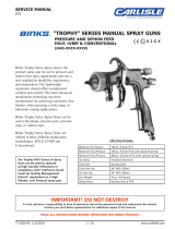
Illustration Key
1. Lightweight Air Nozzle
2. Fluid Inlet 3/8" NPS(m)
3. Extra Smooth Trigger Action
4. Stainless Steel Fluid Nozzle and Needle
5. Side Port Control
6. Fluid Control Knob
7. Forged Aluminum Body
8. Air Inlet 1/4" NPS(m)
4
Binks MACH 1SL HVLP
SPRAY GUN 7000-XXXX-X
Mach 1SLA (7001-XXXX-X)
The Binks MACH 1SL HVLP Gun is a
top quality high performance air spray gun.
You only have to pick it up to feel the
difference. Its superbly balanced forged
aluminum body offers the operator extra
comfort and control. All of the gun’s
components are machined and finished to
exacting tolerances and only the best
materials are used, ensuring years of
peak efficiency.
The MACH 1SL HVLP airspray gun has
special nozzles and modifications that
allow it to operate at high transfer
efficiencies in compliance with the
“California South Coast Air Quality
Management District” regulations as a
“high volume, low pressure” airspray gun.
The air inlet passage in the gun body
incorporates a venturi which limits
airflow. High pressure, low volume
airflow is converted to high volume, low
pressure at this point. Special air and fluid
nozzles enable the gun to atomize fluid at
low air pressures and velocities, creating
the “soft spray” effect for high transfer
efficiencies.
To obtain optimum performance from
your new MACH 1SL HVLP airspray
gun, read all instructions carefully.
Package Contents
Please note that your Binks MACH
1SL HVLP airspray gun package was
shipped with the following contents.
If anything in the following list is miss-
ing, call 1-800-99-BINKS for a prompt
shipment to you of the missing item.
1 MACH 1SL Spray Gun
1 Part Sheet ............ 77-2665
1 Gunners Mate
1 Gun Brush
5
6
7
2
1
3
8
Replaces
Part Sheet
77-2665R-11
Part
Sheet
77-2665R-12
NOTE
IMPORTANT REGULATORY NOTE regarding
the use of this product appears on page 8.
CA PROP
65
PROP 65 WARNING
WARNING: This product
contains chemicals known to
the State of California to cause
cancer and birth defects or
other reproductive harm.
FOR FURTHER SAFETY INFORMATION
REGARDING BINKS AND DEVILBISS
EQUIPMENT, SEE THE GENERAL
EQUIPMENT SAFETY BOOKLET (77-5300).
IT IS THE RESPONSIBILITY OF THE
EMPLOYER TO PROVIDE THIS
INFORMATION TO THE OPERATOR
OF THE EQUIPMENT.

TYPES OF INSTALLATION
2
5/16" 1/4"
Only 34 PSI at gun inlet
25 feet of 1/4" I.D. hose causes
a drop of 26 PSI between the
air supply and the gun.
(NOT RECOMMENDED)
48 PSI at gun inlet
25 feet of 5/16" I.D. hose
causes a drop of 12 PSI
between the air supply
and the gun. For this reason
Binks recommends the use
of 5/16" hose.
(RECOMMENDED)
With 60 psi applied at air supply
CONNECTING GUN TO
“PRESSURE ASSISTED” 1 QT. CUP
(Figure 1)
The stainless steel pressure-assisted
1-quart cup utilizes a low pressure air
bleed port on the gun head to slightly
pressurize the cup and provide fluid flow
to the nozzle. A check valve prevents the
cup from depressurizing when the gun
trigger is released and airflow stops.
To connect the gun to the cup, remove the
plug (18) in the gun head and install the
hose barb fitting provided with cup assem-
bly. Attach cup assembly to 3/8" NPS fluid
inlet connection and firmly tighten. The
siphon tube should be angled toward the
front of the gun, i.e. under the nozzles,
and the pressure hose in the cup lid posi-
tioned to the left of the trigger. Connect
check valve assembly hose from bard fit-
ting on gun head to check valve inlet fit-
ting on cup cover. Make sure the check
valve is connected so the air comes from
the gun, through the check valve, into
the cup.
Air pressure for atomization is regulated
at the extractor. The flow of the fluid is
adjusted by the fluid valve control
knob on gun, viscosity of paint and
air pressure.
PRESSURE CUP HOOKUP
(Figure 2)
For fine finishing with limited spraying.
Air pressure for atomization is regulated
at extractor; fluid pressure at cup regula-
tor. pressure cup is also available less
regulator.
PRESSURE TANK HOOKUP
(Figure 3)
For medium production spraying (single
regulator). Air pressure for atomization is
regulated at extractor, fluid pressure at
tank regulator.
PRESSURE TANK WITH
2 REGULATORS (Figure 4)
The pressure to the tank is regulated by
the first regulator. The pressure for
atomization is regulated by the second
regulator.
PRESSURE CIRCULATING
HOOKUP (Figure 5)
For heavy production spraying. Air
pressure atomization regulated at extractor.
Fluid pressure regulated at fluid regulator.
AIR PRESSURE
Atomizing pressure must be set
properly to allow for the drop in
air pressure between the regulator
and the spray gun.
Binks oil and water extractor is important.
Achieving a fine spray finish without the use of a good oil and water extractor is virtually
impossible.
A Binks regulator/extractor serves a double purpose. It eliminates blistering and spotting by
keeping air free of oil and water, and it gives precise air pressure control at the gun.
Binks recommends using the HFRL-508 oil and water extractor/regulator.
See your local distributor for models.
Cross section view
showing comparison of inside
hose diameters (actual size).
60 lbs. regulated pressure
Air
Oil & Water
Extractor
Fluid Pressure Cup
FIG 3
Air
Fluid
Outlet
Air
Inlet
Oil & Water Extractor
Fluid
Pressure
Tank
FIG 4
FIG 5
Fluid
Regulator
Air Supply
Air Supply
Fluid
Pressure
Tank
Oil &
Water
Extractor
Air
FIG 1
FIG 2
Air
Cup Regulator
Oil & Water
Extractor
Fluid
Pressure-Assisted Cup

3
OPERATION AND MAINTENANCE FOR MACH 1SL HVLP SPRAY GUN
Your new MACH 1SL HVLP spray gun
is exceptionally rugged in construction
and is built to stand up under hard, con-
tinuous use. However, like any other fine
precision instrument, its most efficient
operation depends on a knowledge of its
construction, operation and maintenance.
Properly handled and cared for, it will
produce beautiful, uniform finishing
results long after other spray guns have
worn out.
SET-UP FOR SPRAYING
Connecting Gun To Air Hose
Air should be supplied by a suitable
length of 5/16" diameter air hose fitted
with a 1/4" NPS(f) connection at gun
end. For hose lengths over 50', use 3/8"
diameter hose.
Connecting Gun To Fluid Hose
Fluid should be supplied by a suitable
length of 3/8" diameter fluid hose fitted
with a 3/8" NPS(f) connection at gun end.
1/4" diameter hose is recommended for
use with low viscosity fluids. (Fluid hoses
of different composition are available for
special fluids.)
SPRAY GUN CLEANING
INSTRUCTIONS
In certain states it is now against the law
to spray solvents containing Volatile
Organic Compounds (VOC)’s into the
atmosphere when cleaning a spray gun.
In order to comply with these air quality
laws Binks recommends one of the fol-
lowing two methods to clean your spray
finishing equipment:
1. Spray solvent through the gun into a
closed system. An enclosed unit or
spray gun cleaning station condenses
solvent vapors back into liquid form
which prevents escape of VOC’s into
the atmosphere.
2. Place spray gun in a washer type
cleaner. This system must totally
enclose the spray gun, cups, nozzles
and other parts during washing, rins-
ing and draining cycles. This type of
unit must be able to flush solvent
through the gun without releasing any
VOC vapors into the atmosphere.
Additionally, open containers for storage
or disposal of solvent or solvent-contain-
ing cloth or paper used for surface prepa-
ration and clean-up may not be used. All
containers shall be nonabsorbent.
Pointers On Cleaning
When used with 1-quart cup relieve pres-
sure in the cup. Then unscrew, empty and
carefully rinse cup out with thinners.
Place clean thinners in the cup and spray
this through the gun until it is clean.
Blow air through gun to dry it.
When Used With
Pressure Container
Shut off air supply to container and
release the pressure on the container.
Hold a piece of cloth wadded in the
hand over the gun nozzle (3) and pull the
trigger. The air will back up through the
fluid nozzle and force the fluid out of the
Hose into the container. Empty container.
Put enough thinner into the container to
wash hose and gun thoroughly and spray
this through the gun until it is clean. Then
blow out the fluid hose to dry it and
remove all traces of fluid by attaching it
to the air line.
When used with Paint
Circulating System
Shut off fluid supply and remove fluid
hose from gun. Clean as gun used with
siphon cup or pressure container or
connect quick release on paint line
solvent line. To ensure a clean air supply
to your spray gun, use Binks oil and
water extractor. See your Binks distributor
for the correct model.
GENERAL MAINTENANCE
To Replace Air Valve and
Spindle Assembly
Remove fluid control knob (19), spring
(14) and fluid needle (16). Unscrew hous-
ing (15) and remove spindle assembly
(13) with springs (12 & 14), seal retainers
(11) and o-rings (10). Lubricate new
o-rings with Binks Gunner’s Mate. In the
absence of Gunner’s Mate, a sparing
amount of petroleum jelly can be used. If
too much petroleum jelly is used, the air
passages will carry it into the finished
product.
Assemble components using fluid needle.
Place this assembly along with housing
(15) into gun body and screw into posi-
tion. Remove fluid needle and tighten
housing.
To Replace Cartridge Assembly
Remove fluid control knob (19), spring
(14) and remove fluid needle (16). Pull
back trigger (23) and remove seal car-
tridge assembly (25) from fluid inlet (24).
Remove and discard plastic packing pin
in new seal cartridge assembly. Attach
seal cartridge assembly to fluid inlet.
Assemble fluid needle (16), spring (14)
and fluid control knob (19) to gun.
CAUTION
All parts on a spray gun should be
screwed in hand tight at first; this will
avoid the possibility of cross threading
the parts. If the parts cannot be turned
by hand easily, make sure you have
the correct parts, unscrew, realign, and
try again. NEVER use undue force in
mating parts.
!

4
Binks MACH 1SL, MACH 1SLA (ADJUSTABLE FLUID INLET), AND MACH 1SLV
ITEM PART
NO. NO. DESCRIPTION QTY.
1 54-3531 RETAINER RING (Metal) ........................ 1
2 * AIR NOZZLE ......................................... 1
3 * FLUID NOZZLE ..................................... 1
4 54-3543 HEAD INSERT ....................................... 1
5 54-4339 GUN BODY ASSEMBLY ........................ 1
6 54-3919 TRIGGER STUD AND SCREW KIT ........ 1
7 54-4343 SIDE PORT CONTROL ASSEMBLY ........ 1
8 54-3511▲ RETAINING RING.................................. 1
9 20-6160▲ O-RING ................................................. 1
10 20-4615▲ O-RING ................................................. 2
11 54-3515 SEAL RETAINER .................................... 2
12 54-3520▲* SPRING (Yellow) .................................... 1
13 54-3512▲ SPINDLE ASSEMBLY ............................. 1
14 54-3518▲* SPRING (Blue) ........................................ 2
14a 54-4427* HEAVY DUTY SPRING (Optional)
14b 54-3559* S.S. SPRING (Optional)
15 54-3541 HOUSING ............................................. 1
16 * FLUID NEEDLE .................................... 1
17 54-3925 GASKET ................................................ 1
18 54-3928 PLUG .................................................... 1
19 54-3606 FLUID VALVE CONTROL KNOB ........... 1
20 54-768 AIR CONNECTION ................................ 1
21 20-2287 PLUG 1/8" NPT ...................................... 1
22 54-3513 VALVE SPINDLE CAP ............................ 1
ITEM PART
NO. NO. DESCRIPTION QTY.
23 54-4360 TRIGGER ............................................... 1
24 54-3742 FLUID INLET (Mach 1SL) ........................ 1
25 54-4370▲ SEAL CARTRIDGE ASSEMBLY
(Mach 1SL and Mach 1SLA).................... 1
26 54-4330 ADJUSTABLE FLUID INLET
ASSEMBLY (Mach 1SLA) ...................... 1
27 82-221 FLAT BRUSH ......................................... 1
28 54-3918● WRENCH (Not Included - Optional)
29 OMX-88 GUN BRUSH ......................................... 1
30 54-4440● QUICK CHANGE SIDE PORT
CONTROL ASSEMBLY
(Optional - Not Shown)
31 54-4541●† FLUID INLET (Mach 1SLV) ...................... 1
32 20-2227●†▲ O-RING (Mach 1SLV) .............................. 1
33 54-4531●†▲ SPACER (Mach 1SLV) .............................. 1
34 54-4542●† NUT ASSEMBLY (Mach 1SLV)................. 1
54-3871▲ GUNNERS MATE 3cc (Not Shown) ........ 1
35 54-4333 FLUID INLET ......................................... 1
36 54-4337 PACKING SEAL ..................................... 1
37 54-4332 SEAL CARTRIDGE ASSEMBLY .............. 1
38 54-4540● FLUID INLET ASSEMBLY (Mach 1SLV) .... 1
PARTS LIST
(When ordering, please specify Part No.)
* See Air and Fluid Nozzle Chart on page 5.
▲ Included in 54-4278 Spare Parts Kit.
● Optional – Order separately.
†For vitreous set-up.
33
1
25
26
27
28
29
17
18
31
24
32
22
23
7
8
15
20
21
13
12
14
14
19
2
3
4
5
6
6
9
11
11
10
10
34
Not Included
Optional for
vitreous
applications.
25
35
36 37
38
16
Torque Specs:
Item #4 Head insert
20-23 ft/lbs
Item #3 Fluid Nozzle
120-140 in/lbs
Item #1 Retaining ring
10-15 in/lbs

5
94VT (.052”) 1.3mm Carbide Tip 94P, 97P, 100P 54-4383 VT
903 (.079”) 2.0 mm
54-4382/54-4381
905 (.089”) 2.3 mm 905P 54-4382/54-4381
906 (.100”) 2.5 mm 54-4382/54-4381
909 (.111”) 2.8 mm 54-4382/54-4381
STANDARD FLUID NOZZLES
FLUID NOZZLES
94P
97P
91P, 92P*
95AP**●
97AP**●
ULTRA LIGHT / Reduced Flow 89 (.020” Dia.) 0.5 mm
VERY LIGHT / Reduced Flow 90 (.030” Dia.) 0.8 mm
LIGHT: less than 15 to 20 seconds in a Zahn 2 Cup, 91 (.040” Dia.) 1.0 mm 90P***,
e.g., stains, varnishes, thin lacquers, automotive refinishing fluids. 92 (.046” Dia.) 1.2 mm 95P, 97P,
93 (.051” Dia.) 1.3 mm 92P* SEE NOTE
MEDIUM: 20 to 60 seconds in a ZAHN 2 Cup, 94 (.055” Dia.) 1.4 mm 95AP, 97AP**
e.g., general industrial coatings. 95 (.059” Dia.) 1.5 mm 93P, 94P, 100P
96 (.063” Dia.) 1.6 mm
HEAVY: greater than 60 seconds in a Zahn 2 Cup. 97 (.070” Dia.) 1.7 mm
FLUID FLUID NOZZLE NO.
APPLICABLE
AIR NOZZLE
FLUID
NEEDLE
NOTE: Use stainless steel fluid needle (54-4382) for all above nozzles. Optional nylon-tipped stainless steel fluid needle (54-4381) is also available.
SPECIAL PURPOSE NOZZLES
TYPICAL APPLICATION FLUID NOZZLE NO.
APPLICABLE
AIR NOZZLE
COMPATIBLE
FLUID
NEEDLE
VERY HEAVY FLUIDS:
Block Fillers, Texture Coatings, Fire
Retardants, Road Marking Paint,
Bitumastics, Adhesives, Celluar
Plastisols, Underbody & Vitreous
Coatings, Special Applications
FEATHERING
For applications requiring more
gradual fluid valve opening for
metering control of fluid flow
with trigger
SIPHON FEED-FINE FINISH
Light to medium fluids
Auto body spot repairs
Medium to heavy fluids
Auto body overall finishing
94s (.055") 1.4 mm 95AS● 54-4390
97s (.070") 1.7 mm 54-4391
GS FLUID NOZZLES
LIGHT/MEDIUM: less than15 to 20 seconds in a Zahn 2 Cup, 92GS (.046” Dia.) 1.2 mm SEE NOTE
e.g., stains, varnishes,thin lacquers, automotive refinishing materials. 94GS (.055” Dia.) 1.4 mm
MEDIUM: 20 to 60 seconds in a ZAHN 2 Cup, 96GS (.063” Dia.) 1.6 mm 96G ■ 54-4547
e.g., general industrial coatings.
FLUID FLUID NOZZLE NO.
APPLICABLE
AIR NOZZLE
FLUID
NEEDLE
NOTE: Optimum setup for clear coat spray is 92GS Fluid Nozzle x 96G Air Nozzle Assembly.
* 92P Low Volume Nozzle for general industrial and
automotive fine finish.
** 95AP High Solids Nozzle for hard to atomize
coatings and higher flow rates. 97AP same as
95AP, but for wider fan if needed.
*** 90P Low Volume Nozzle, 1 1/2 H.P. Compressor or
bigger – (6 C.F.M) required.
● 95AP, 95AS and 97AP Air Nozzles do not require
separate Retainer Ring.
■ Improves atomization, breaks-up high solid material
easier, provides better finish at lower pressures
and reduces orange-peel dramatically.
54-4547 needle must be used in conjunction
with the GS fluid nozzle and 96G air nozzle.
54-4387
54-4389
54-4390
54-4391
90F (.030") 0.8 mm
92F (.046") 1.2 mm
94F (.055") 1.4 mm
97F (.070") 1.7 mm

Primer/surfaces 3-4 1-4
Light Stains, Inks 4-5 1-5
Acrylic Enamels 6-7 2-7
Lacquers 7-8 2-8
Low VOC, Urethanes 8-10 2-10
6
TYPE OF FLUID ATOMIZING FLUID PRESSURE
PSI RANGE- PSI
AIR PRESSURE RECOMMENDATIONS
HVLP AIR NOZZLES
Maximum recommended nozzle
atomizing pressure is 10 psi. The
95P and 905P air nozzles are most
suitable for conventional materials.
Use of very low fluid delivery rates
with these nozzles will produce a
narrower than normal fan pattern.
Use the 97P air nozzle for heavy
bodied, high solids materials and
low fluid rates with conventional
materials. High flow rates with light
bodied materials may result in some
minor “smoking” or fluid build-up
on the face of these nozzles.
HOW TO USE THE
NOZZLE SELECTION
CHART
HVLP AIR NOZZLES
95P, 97P, 95AS, 95AP, 97AP, 905P
HVLP AIR NOZZLE 92P
NOZZLE AIRFLOW
SCFM
SIDE PORT
CONTROL
REGULATOR*
PSI
REGULATOR*
PSI
GUN INLET
PSI
3.0 11.0 20.0 27.0
5.0 15.7 30.0 40.0
7.0 17.5 38.0 50.0
9.0 19.6 45.0 58.0
10.0 22.5 50.0 64.0
NOZZLE ATOMIZING
PSI
NOZZLE AIRFLOW
SCFM
SIDE PORT
CONTROL
3.0 4.5 6.0 9.0
5.0 6.0 8.5 10.0
7.0 6.8 11.0 14.0
9.0 7.5 13.5 18.0
10.0 8.0 15.0 19.0
* NOTE: Regulator pressures are based on 25' of 5/16" diameter hose in good condition without quick-disconnects or other restrictive fittings.
Use the air nozzle test gauge accessory to confirm the atomizing/regulator pressure relationship for your actual air supply set-up.
These recommendations are for “typical” or “average” fluids, and are intended to serve as a starting point. Adjust as necessary for
your specific application.
HVLP AIR NOZZLE 90P
HVLP AIR NOZZLE* 94P
NOZZLE ATOMIZING
PSI NOZZLE AIRFLOW
SCFM
SIDE PORT
CONTROL
GUN INLET
PSI
3.0 4.0 5.0
5.0 4.5 7.0
7.0 5.0 10.0
9.0 5.5 12.0
10.0 6.0 15.0
Side Port
Nozzle Nozzle Control
Atomizing AIR FLOW GUN INLET
PSI SCFM PSI
3.0 7.0 14.0
5.0 9.0 21.0
7.0 11.0 27.0
9.0 12.0 30.0
10.0 13.0 33.0
NOZZLE ATOMIZING
PSI
NOZZLE AIRFLOW
SCFM
SIDE PORT
CONTROL
REGULATOR*
PSI
GUN INLET
PSI
3.0 5.5 8.0 10.0
5.0 7.0 11.5 14.0
7.0 8.0 14.5 18.0
9.0 9.5 17.0 22.5
10.0 10.0 18.0 24.0
HVLP AIR NOZZLE 93P
NOZZLE ATOMIZING
PSI
GUN INLET
PSI
AIR NOZZLES
HVLP AIR NOZZLE 100P
Gun Nozzle Nozzle
Inlet AIR FLOW Atomizing
PSI SCFM PSI
3.0 3.2 2
6.1 4.8 4
9.0 6.0 6
11.6 6.9 8
14.3 8.0 10

SPRAY TECHNIQUE
The first requirement for a good resultant
finish is the proper handling of the gun.
The gun should be held perpendicular
to the surface being covered and moved
parallel with it. The stroke should be
started before the trigger is pulled and the
trigger should be released before the
stroke is ended. This gives accurate
control of the gun and fluid.
The distance between gun and surface
should be 6 to 12 inches depending on
fluid and atomizing pressure. The fluid
deposited should always be even and wet.
Lap each stroke over the preceding stroke
to obtain a uniform finish.
GENERAL SPRAY INSTRUCTIONS
To reduce overspray and obtain maximum
efficiency, always spray with the lowest
possible fluid/air pressure that produces
an acceptable spray pattern.
For best results, use 3 to 6 psi fluid pres-
sure. Higher than 6 psi fluid pressure may
be required for heavy-bodied materials.
Low fluid pressures will produce a nar-
rower than normal spray pattern.
Generally use 30-35 psi air at gun inlet
(see page 6). Unusually heavy, difficult to
atomize fluids may require up to 50 psi
air at gun inlet.
CONTROLLING THE FAN SPRAY
The fan spray is controlled by means of
the side port control assembly (7).
Turning this control clockwise until it is
closed will give a round spray; turning it
counterclockwise will widen the spray
into a fan shape. The fan spray can be
turned anywhere through 360 ° by posi-
tioning the air nozzle (2) relative to the
gun. To accomplish this, loosen retaining
ring (1), position nozzle (2), then tighten
retaining ring (1).
CONTROLLING THE FLUID FLOW
When used with a pressure assisted cup,
an increase in air pressure will increase
the rate of flow. When fed from a pres-
sure supply, an increase in the fluid pres-
sure will increase the rate of flow. Correct
fluid nozzle size should be selected for
correct fluid flow rate. The fluid control
knob (19) may be used to restrict the (3)
fluid nozzle opening and reduce the fluid
flow as necessary.
AIR NOZZLE, FLUID NOZZLE,
FLUID NEEDLE
1. All nozzles and needles are precision
made. They should be handled with
care.
2. Do not make any alterations in the
gun. To do so could cause finishing
difficulties.
3. To clean nozzles, soak them in solvent
to dissolve any dried material, then
blow them clean with air.
4. Do not probe any of the holes in the
nozzles with metal instruments. If
probing is necessary, use only a tool
that is softer than brass.
TROUBLESHOOTING
Faulty Spray
A faulty spray pattern is often caused by
improper cleaning resulting in dried mate-
rials around the fluid nozzle tip or in the
air nozzle. Soak these parts in thinners to
soften the dried material and remove with
a brush or cloth.
Intermittent Spray
If the spray flutters, it is caused by one
of the following faults:
1. Insufficient fluids available. Check
supply and replenish if necessary.
2. Pressure vent tube from gun body
to pressure assist cup is loose or
leaking.
3. Check valve in pressure assist cup
is stuck or blocked.
4. Pressure assist cup cover not suffi-
ciently tight or cover gasket defective.
5. Insufficient fluid pressure from stan-
dard pressure pots.
7
OPERATING THE MACH 1SL
HVLP SPRAY GUN
CAUTION
NEVER USE METAL INSTRUMENTS TO
CLEAN THE AIR OR FLUID NOZZLES. THESE
PARTS ARE CAREFULLY MACHINED AND
ANY DAMAGE TO THEM WILL CAUSE
FAULTY SPRAY. If either the air nozzle (2)
or fluid nozzle (3) are damaged, these
parts must be replaced before perfect
spray can be obtained.
!
NOTE
To reduce overspray and obtain maximum
efficiency always spray with the lowest
possible atomizing air pressure.
NOTE
Excessive atomizing air pressures can
increase overspray, reduce transfer
efficiency, and with some materials,
result in poor finish quality from dry
spray. Atomizing air pressures should
not exceed 10 psi. See table on page 6,
diagram on page 2 and regulatory note
on page 8.

Some regulatory agencies prohibit the operation of HVLP spray guns above 10 psi nozzle atomizing pres-
sure. Users subject to this type of regulation should not exceed 10 psi (50 psi gun inlet pressure). See Air
Pressure Recommendations, page 6 and General Spray Instructions, page 4. It is recommended that the
nozzle test gauge (see below) be used to confirm actual nozzle operating pressure.
It may also be a requirement of some regulatory agencies that users have this gauge nozzle available on
site to verify that the gun is being operated within the limits of applicable rules.
IMPORTANT REGULATORY NOTE
Part Number Description
54-3908* 900 SERIES
54-3935 95 and 97 SERIES, 95AP and 97AP
54-4078* 95AS and 97AS NOZZLES (Siphon)
54-4345* 90P NOZZLE
54-3902 92P NOZZLE
54-4356 93P NOZZLE
54-4066* 94P NOZZLE
54-4566 96G NOZZLE
54-5650 100P NOZZLE
*Available from Industrial Finishing distributors only.
59-299 Gauge
8/11 ©2011 Binks All rights reserved. Printed in U.S.A.
U.S.A./Canada Customer Service
195 Internationale Blvd.
Glendale Heights, IL 60139
630-237-5000
Toll Free Customer Service
and Technical Support
800-992-4657
Toll Free Fax
888-246-5732
Binks Sales and Service: www.binks.com
WARRANTY
This product is covered by Binks’ 1 Year Limited Warranty.
77-2665R-12 Revisions: (P8) Revised gauge list,
updated contact information.
/