Page is loading ...

No. 3420, 1
st
Floor, Service Road, RPC Layout (West), Vijayanagar, Bangalore – 560040
Phone: +91-80-23180601 | Email: [email protected]
URL: www.itriangle.in | Tracking: www.aquilatrack.com
Foreword
Dear Customer,
Thank you for purchasing aQuiLa
TM
Track.
User Manual - aQuila Track S101
Vehicle Tracking and Fleet Monitoring Solutions

aQuiLa
TM
Track S101 is a compact, easy to install and highly reliable Vehicle Tracking and Fleet Management System that
increases the efficiency, productivity and safety, through real-time & precise tracking of position and status of your vehicle.
aQuiLa
TM
Track S101 is developed using Global Positioning System (GPS), coupled with Google Maps and GSM Mobile
technology to communicate real time information to the Web based highly user friendly online tracking application software
aQuiLa
TM
Track is made of high quality components and material to provide very high durability and efficiency to meet
customer expectations and carries a warranty of 1 year as per the terms & conditions stated in the Warranty Policy provided
in this book.
While iTriangle Infotech takes every care in making the product trouble free, in the unlikely event of failure of the product,
iTriangle Infotech ensures the rectification of problem within a shortest possible time keeping the business interest of its
customers.
Kindly refer to different sections of this manual for more details on our Service Policy.
Thanking you once again and assuring you of our best services at all times,
Vadiraj S Katti
Managing Director

Copyright Notice:
The information disclosed herein is the exclusive property of iTriangle Infotech Pvt. Ltd and no part of this document can be
reproduced or transmitted in any form or by any means including electronic storage, reproduction, and/or execution without
the prior written permission from iTriangle Infotech Pvt. Ltd. The information contained in this document is subject to
change without notice and should not be construed as a commitment by iTriangle Infotech Pvt. Ltd unless such commitment
is expressly given in a separate document
iTriangle InfoTech Pvt. Ltd © Copyright notice and statement that “No part of this document may be reproduced without the prior written
consent of iTriangle InfoTech Pvt. Ltd”
Disclaimer and Limitation of Liability
iTriangle Infotech Pvt. Ltd takes no responsibility for any damage or loss resulting from the use of its products or services
and will not be liable to compensate any kind of losses or claims by any parties, which may arise through the use of products
or services offered by iTriangle Infotech Pvt. Ltd
While the information contained herein is assumed to be accurate, iTriangle InfoTech Pvt. Ltd assumes no responsibility for
any errors or omissions.

Contents
1.1. About this document 6
1.2. Symbols Used in this Manual 6
1.3. aQuila S101 device 7
1.4. Installation 7
1.5. Section 1: Introduction to aQuila Track S101 8
1.6. About aQuila Track S101 8
1.7. How aQuila Track Hardware works? 8
1.8. aQuila Track Working Diagram 10
1.9. Device parts 11
1.10. Section 2: aQuila Track S101 Device Installation 12
1.11. Tools required for installation 13
1.12. Consumable material required for installation 14
1.13. Installation Steps 15
1.14. POWER CONNECTION – COMMERCIAL VEHICLES 16

1.15. POWER CONNECTION – PERSONAL 4 WHEELERS 16
1.16. CONNECTION TO IGNITION OUTPUT IN THE VEHICLE 17
1.17. FUEL WIRE CONNECTION AND CALIBRATION 18
1.18. PICTURE – DEVICE PLACEMENT IN CAR 21
1.19. PICTURE – DEVICE PLACEMENT IN TRUCK 22
1.20. PICTURE – DEVICE PLACEMENT IN 2 WHEELER 23
1.21. How to insert SIM card in to the device 24
1.22. Troubleshooting 25
1.23. Problem: Device does not track 26
1.24. Warranty Policy 27
1.25. Contact Us: 30

About this document
This manual is designed to guide you through installation of aQuiLa
TM
Track S101device and trouble shooting of problems
step-by-step. The manual is divided in to two sections. Section-1 covers the various features of S101 and Section-2
covers installation and trouble shooting.
iTriangle Infotech recommends users to read the manual completely and carefully before using aQuiLa
TM
Track S101.
Symbols Used in this Manual
In this manual, we apply easily understood language and many drawings in order to simplify the installation procedure.
Warning indicates that ignoring the warning may cause permanent damage to the device or injury to the person.
Tip, indicates some information, which may be useful and effective while installing or trouble shooting the
device. Experienced or qualified person can skip this information.
Note gives additional information relating to the topic that is being discussed.


Section 1: Introduction to aQuilaTrack S101
About aQuila TrackS101
aQuila TrackS101 is a complete Vehicle Tracking and Fleet Management Hardware. It is a robust, compact and high
performance GPS / GSM based electronic device designed to be fitted in any vehicle. It records the vehicle location and
events data at regular intervals, which is configurable to meet the user requirement and transmits the data to central server
to make it user understandable data.
aQuila Track helps user to get data on different events of the vehicle, while on move as well as when stationary. It gives vital
information like vehicle location, speed, date, time, distance and usage of selected in-vehicle gadgets and equipment
like, Engine usage and Fuel. aQuilaTrack S101 comes with 2 Digital I/Os that can be configured to provide alerts on any 2
of the events like Door Open/Close, Vehicle AC On/Off, Emergency Button Press, etc. aQuila Track S101 can be configured
to send Alerts for Stoppage and Over Speed of the vehicle.
How aQuila Track Hardware works?
aQuilaTrack S101 is a Vehicle Tracking, Fleet Management and Remote Data Acquisition hardware designed to suit every requirement. It
comes in a compact, portable and rugged whether proof enclosure. It comprises of world class GPS and GSM modules.
Where, GPS records the location, date, time, speed and distance at regular intervals and the Event Management Module
records different events of the vehicle. GSM transmits the GPS and Event data to central server at pre-configured intervals.
Every aQuila Track device requires a SIM card of a GSM mobile operator to send the data to the central server and for voice
communication. The data from device to the central server is sent in the form of GPRS Packets at every 2 minutes
aQuila Track device can be configured to record the data at an interval as low as 30 seconds and transmit the data to the
central server at a minimum interval of 1 minute. That means, the latest vehicle location gets updated once every 1 minute.

Reducing tracking interval increased the GPRS data usage and expenses. iTriangle will not be
liable to pay any compensation and/or penalty for the increased expenses due to increase in GPRS
usage
aQuila TrackS101uses in-vehicle battery power source in the range of 9 – 32 V and works only on DC Power. It is built to
take care of Spikes and Surges. In case of Spikes in the device power line, the safety fuse will blow off to protect the device.
It has a built-in power management to reduce power consumption when the device is idle and/or vehicle is stationary.
If the GSM / GPRS network is not available for transmission of data, the device will store the data in
the memory and transmit to central server once it comes to GSM / GPRS coverage area

aQuila Track Working Diagram

Device parts
1. USB Indicator
2. GPS indicator
3. Processor Indicator
4. GSM indicator
5. USB Port
6. RESET switch
7. On / Off Switch
8. Connectors
9. Red – Vehicle Battery
+ve
10. Yellow – Fuel
11. Black – Ground
12. Green – Ignition
13. Wiring kit
14. Fuse
15.

Section 2: aQuila Track S101
Device Installation
It is highly recommended that Installation of aQuila Track S101 and its accessories must be done by
a trained technician only. All the material mentioned in this section are for indication purpose only
and iTriangle Infotech Put Ltd will not be responsible for any problem and/or damage to person
and/or material caused during / after installation
Handle the device with care and do not place any heavyweights on the device. There is a Li-ion
Battery inside. Application of Power, Temperature and Humidity beyond the specified range can
damage device and void Warranty
It is recommended that the aQuila track device not be installed in the places prone to water and
rain. Remove aQuila device during servicing to avoid accidental water splash and high voltages

Tools required for installation
Portable drilling machine for making holes (in case necessary to mount the device)
A standard screwdriver set comprising cross/flat/Phillips screwdrivers of small/medium sizes and a
poker. Choosing one with a magnetic head would be better.
Pliers can be used as an auxiliary tool to pull out the power connectors, hold wires, etc
Forceps can be used to pick up tiny screws and/or SIM card
Rubber gloves can prevent you from being incised and suffering the static charge.
Wire stripper for stripping cables/wires while installing
Torch light for low light / night environments
Cutters for cutting cables/wires while installing
Extra screws of all sizes required in case of accidental misplacement of originally supplied screws
A hammer for better punch
Multimeter for measuring voltage and current.

Micro USB Cable for uploading Configuration, Firmware, etc
Glue Gun to seal any connectors
Consumable material required for installation
Cable ties for tying the wires together
Self-adhesive cable tie mounts to hold the wire harness / wires in a line.
Insulation tape to cover the electrical joints and protect open wires from short circuit
Fevi kwik – Instant adhesive for fixing anything instantly
Double Sided adhesive tape to fix the device firmly under the dash board
Battery Lug Terminals to connect the power cables firmly.
Corrugated (Flexible) PVC Conduit Pipe for protection to Cables / wires

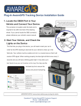
Installation Steps
1) Open the Box and check for contents as specified on the box
2) Take the SIM card that you have purchased from a Mobile Operator
3) Insert SIM card in any Mobile Phone to check, SIM card for Registration, Activation and GPRS connectivity
4) If all parameters are found working, insert the SIM card in the holder as shown in the picture below in this document
5) Switch ON internal Device Battery
6) Connect device to vehicle battery / continuous power source in the vehicle as explained below in this document
7) Keep the vehicle in an Open area
8) Check for Processor Status
a. A healthy Processor is indicated by an LED (RED) on the front panel of the device that will blink at every 4
seconds
b. If the Processor is not working or has a problem, this LED will be steadily ON
9) Check for GPS Fix:
a. The GPS LED (Blue Color) does not blink till the device gets the good GPS Fix
b. Wait for 2-3 minutes for the first time to get GPS Fix
c. Once the Device gets good GPS Fix, the GPS LED starts to blink at every second
10) Check for GSM / GPRS Connectivity:
a. Wait for 2-3 minutes after connecting the device to the vehicle battery to get the SIM registered to the
Operator Network
b. While the device is getting registered to the Mobile Operator network, the GSM LED (Green) will blink
frequently
c. Once the Device is connected to the GSM service provider network the GSM LED (Green) will start to blink
at every 4 seconds.

11) 5-10 minutes after connecting the device to the vehicle battery, all the 3 LEDs start to blink indicating that the device is
communicating with the configured server
POWER CONNECTION – COMMERCIAL VEHICLES
MINI TRUCKS, TRUCKS, BUSES, MINI BUSES, TEMPO / FORCE TRAVELLER, GOODS AUTO, APE, ACE, AND ALL TYPES
OF GOODS VEHICLES
01
Remove the ignition key
02
Run RED (+ve) and BLCK (-ve) wires from battery till the location of device placement. Ensure that the wiring is done
FIRMLY and NEATLY without any hanging or sagging of wires. Use Self-adhesive Cable Tie Mounts and cable ties to do
the wiring.
03
Connect RED wire of Aquila Device Power Cable (Long Cable) to the +ve (RED) cable drawn from the vehicle battery and
ensure that the connection is firm.
04
Connect the BLACK wire of the Aquila Device Power Cable (Long Cable) to the –ve (BLACK) wire drawn from the vehicle
battery and ensure that the connection is firm.
05
Check if the Dash Board is made of Metal or Plastic / Fiber.
06
If the Dash Board is made of Metal, INSTALL THE DEVICE OUTSIDE THE DASH BOARD ONLY and Use IP box to
ensure that the connectors and device are secured from vulnerabilities.
07
If the Dash Board is made of Fiber OR Plastic, DEVICE CAN BE INSTALLED INSIDE THE DASH BOAD and IP Box is not
required.
POWER CONNECTION – PERSONAL 4 WHEELERS
01
Remove the ignition key
02
Identify the power line +ve cable coming from the battery to the ignition switch by measuring the voltage between each of the

wire coming in to the ignition switch assembly.
03
See if the metal conductor in the connector or wire connection point at the ignition switch is accessible, else remove the skin
from each of the wire
04
Firmly hold the +ve (RED) probe of the multimeter to the wire conductor and –ve (BLACK) probe of the multimeter to the
GROUND point (- ve terminal of the vehicle battery OR any screw / bolt directly connected to metal body of the vehicle)
05
Voltage at the +ve wire of the (incoming supply line) ignition should be matching to the battery voltage of the vehicle
06
Check the Voltage at the Ignition input point at
Vehicle OFF condition
Vehicle Ignition ON Condition
Vehicle Engine start condition
Maximum Acceleration at Neutral / stationary
In any condition, the voltage should not exceed 32V. Please do not install the device in the vehicle if the voltage is beyond 32V
07
Connect RED wire of Aquila Device Power Cable (Long Cable) to the +ve (RED) cable at the Vehicle Ignition input by removing
a small portion of the PVC skin at least 2 inch away from the ignition switch (if already removed the skin for testing the voltage,
use the same)
08
Connect the BLACK wire of the Aquila Device Power Cable (Long Cable) to the GROUND by connecting the wire to the –ve
terminal of the vehicle battery OR to the point where GROUND wire of any of the other accessories of the vehicle is connected
and ensure that the connection is VERY FIRM / TIGHT
09
For all vehicles other than Cars and SUVs, it is highly recommended to connect the +ve and –ve of the device directly to the
vehicle battery
CONNECTION TO IGNITION OUTPUT IN THE VEHICLE
01
Take each wire other than the +ve wire connecting the ignition switch assembly and look for a metal conductor / connector pin of
the wire at the switch end, if not found, remove a small portion of the PVC skin at least 2 inch away from the Switch end
02
KEEP THE IGNITION SWITCH IN OFF POSITION AND FOLLOW THE STEPS BELOW:

03
Firmly hold the RED probe of the Multimeter at the skinned portion of each of the wire one-by-one and BLACK probe of the
Multimeter to the GROUND (- ve terminal of the vehicle battery OR any screw / bolt directly connected to metal body of the
vehicle) and measure the Voltage. The Voltage MUST BE ZERO when the Ignition is in OFF position
04
KEEP THE IGNITION SWITCH IN ACCESSORIES POSITION AND FOLLOW THE STEPS BELOW:
05
Firmly hold the RED probe of the Multimeter at the skinned portion of each of the wire one-by-one and BLACK probe of the
Multimeter to the GROUND (- ve terminal of the vehicle battery OR any screw / bolt directly connected to metal body of the
vehicle) and measure the Voltage. The Voltage MUST BE EQUAL TO THE BATTERY VOLTAGE when the Ignition is in
Accessories position At least 1 wire shows ZERO voltage when the ignition is in Accessories position
06
KEEP THE IGNITION SWITCH IN ON POSITION AND FOLLOW THE STEPS BELOW:
07
Take the wire / wires that showed ZERO volts when the Ignition at Accessories position, firmly hold the RED probe of the
Multimeter at the skinned portion of the wire and BLACK probe of the Multimeter to the GROUND (- ve terminal of the vehicle
battery OR any screw / bolt directly connected to metal body of the vehicle) and measure the Voltage. The Voltage MUST BE
EQUAL TO THE BATTERY VOLTAGE when the Ignition is in ON position. Connect the GREEN wire of Aquila Wire Cable (Long
cable) to this wire that showed ZERO when the ignition switch is at Accessories and Showed BATTERY VOLTAGE when the
ignition is at ON position
FUEL WIRE CONNECTION AND CALIBRATION
01
Check for Vehicle Electrical System (Battery Voltage) in all the vehicles. i.e. 12V system or 24V system
02
Calibration must be done separately for each vehicle if the Vehicle Electrical System is different.
03
Check for type / shape of the fuel tank in the vehicle. Calibration must be done separately for each type of tank even if the
Vehicle Electrical system is identical / same
04
In case of multiple vehicles with the same electrical system and type of fuel tank, only one vehicle in the lot may be calibrated
Identify the right fuel power wire:
05
Switch ON the ignition

06
Check the wires at the Fuel Tank side and measure the voltage for anything between 0.1 and 5V (if tank is accessible)
07
If fuel tank is not accessible (in some cars) check each wire in the connector coming in to the instrument cluster (gauges)
for 0-5V analog voltage line. Once the wire is identified, measure the voltage for anything between 0.1 and 5V
08
After measuring the voltage, confirm the fuel wire by following any or all of the given below procedures:
09
Switch OFF ignition and test continuity in the wire coming in to the instrument cluster and the wire at the tank side
10
Switch ON the ignition and shake the vehicle heavily and see if the voltage in the multimeter changes by more than
500 mV or above
11
Connect Yellow wire of the aQuila device to the confirmed Fuel wire of the vehicle
12
Connect Green wire of the aQuila device to the ignition
13
Connect RED to +ve terminal of the battery or battery line coming in to the vehicle at Ignition section near steering and ensure
that the full battery voltage (12V / 24V) is present even when the Ignition key is removed
14
Connect BLACK wire of the aQuila device to the Ground point in the vehicle (any screw / bolt directly fastened to the metal body
of the vehicle) or to the –ve terminal of the vehicle battery
15
Confirm that the device is tracking and ignition status changes in the aQuila Track Web Application
16
Empty the tank to dry and measure the voltage and note the same
17
Start the Engine and note the Empty Tank Voltage when the engine is running

18
Calibrate Fuel Tank based on the capacity by filling Fuel at consistent regular steps as per below table:
TANK
CAPACITY
RECOMMENDED
FILLING STEPS
Up to 30 ltr
1 ltr
30 - 80 ltr
2 ltr
80 - 150 ltr
5 ltr
150 and above
10 ltr
19
Wait for 1 – 2 minute OR till the 1
nd
digit after decimal point in the voltage value settles in the multimeter and record the value
read in the multimeter
20
Read the FULL TANK voltage and record the same
21
After recording the full tank voltage, start the engine and read the voltage value of the fuel line and record the same separately
22
RECORD CALIBRATION VALUES IN FUEL CALIBRATION REPORT ONLY
23
Submit the Calibration Reading to office immediately after the calibration either over phone or in person
24
NOTE THAT THE IGNITION CONNECTION IS MUST
25
NOTE THAT THE IGNITION MUST BE KEPT “ON” THROUGHOUT THE CALIBRATION PROCESS
/