M968852 Rev.1.3
Certified to comply with ASME A112.18.1M
U.S. Patent No. 5,819,789
HOT
COLD
Turn off hot and cold water
supplies before beginning.
CAUTION
Installation
Instructions
2064.451
ROUGHING-IN DIMENSIONS
1
2" D.
(52mm)
1"
(25mm)
2" MIN.
(51mm)
3" MAX.
(76mm) MAX.
FINISHED
WALL
FINISHED
WALL
2" D.
(52mm)
9-1/4"
(235mm)
1/2" NPT INLETS
8"
(203mm)
4"
(102mm)
CROSS
HANDLE
1
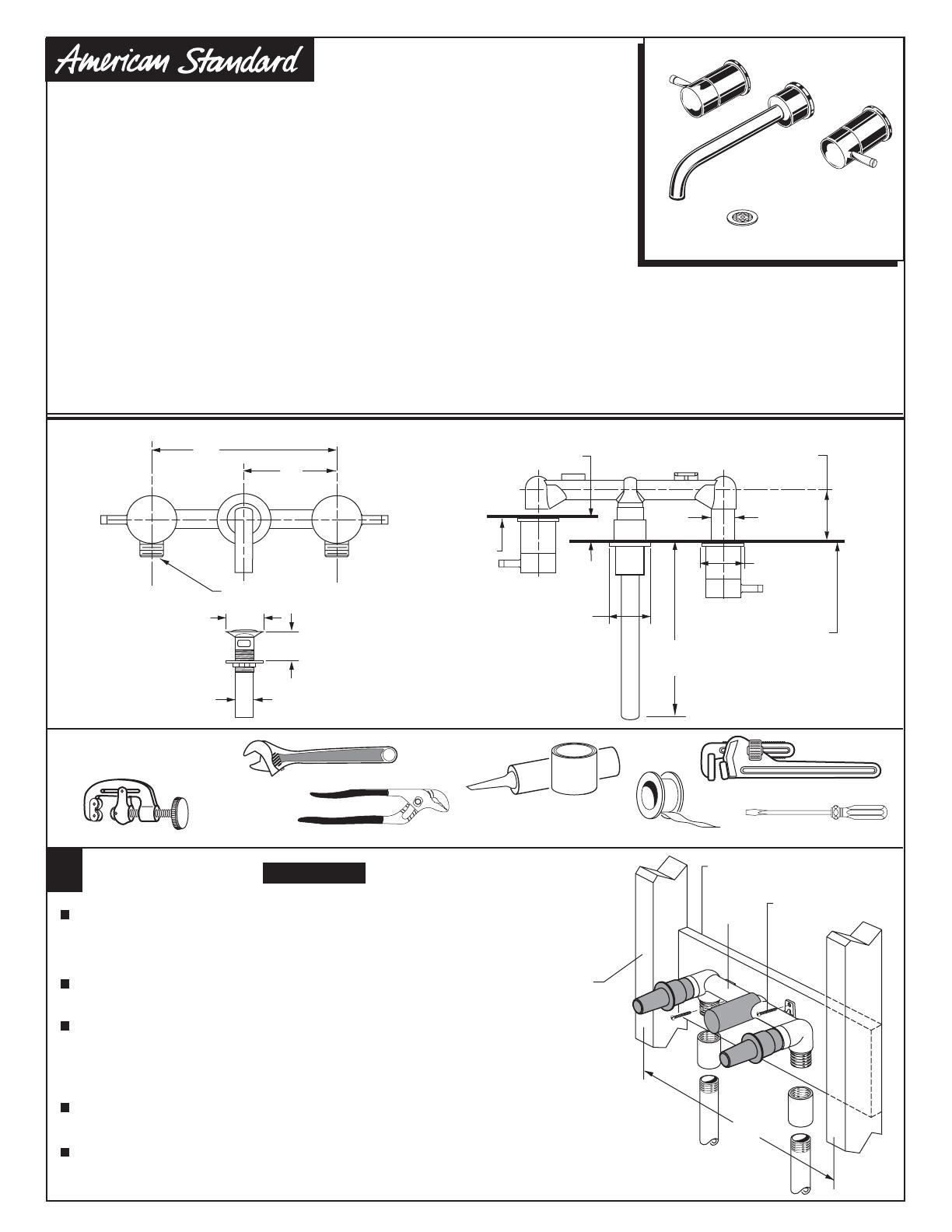
INSTALL VALVE BODY
Determine where the finished wall location will be. This measurement
is very important! Note: The rough-in measurement from the finished
wall is; 2" minimum and 3" maximum. This is a 1" tolerance. See
rough-in illustration above.
Secure FAUCET BODY (1) to cross brace of wall structure
at required height using two wood screws.
Turn valves to off position. Turn hot and cold supplies on and
check fitting connections for leaks .
Complete wall construction.
WOOD SCREWS
HOT
COLD
CROSS BRACE
WALL STUDS
16"
M
A
X
W
A
L
L
M
I
N
1
-
5
/
8
"
D
E
E
P
M
A
X
W
A
L
L
M
I
N
1
-
5
/
8
"
D
E
E
P
Connect HOT water supply to left VALVE inlet and COLD water
supply to right VALVE inlet. Use pipe sealant or Teflon tape for
all threaded connections. For sweat connections, do not make
sweat connections directly to valve body. Damage to seals and
and valve cartridge may occur.
Required Tools
Flat Blade Screwdriver
Adjustable Wrench
Channel Locks
2-1/8" D.
(54mm)
2" MAX. (51mm) MAX.
1-1/4" O.D.
(32mm) O.D.
Pipe Wrench
Teflon Tape
Plumbers' Putty or
Caulking
Tubing Cutter
WALL MOUNT FAUCET
IN-WALL LAVATORY FITTING
SERIN
™
To ensure that your installation proceeds smoothly-please read these instructions carefully before you begin.
Thank you for selecting American-Standard...
the benchmark of fine quality for over 100 years.
To ensure that your installation proceeds smoothly--
please read these instructions carefully before you begin.


