Introduction- 5 -
English
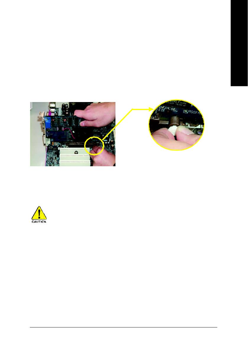
Chapter 1 Introduction
to be continued......
Features Summary
(Note 1) Due to standard PC architecture, a certain amount of memory is reserved for system usage and
therefore the actual memory size is less than the stated amount.
For example, 4 GB of memory size will instead be shown as 3.xxGB memory during system startup.
CPU — Socket 478 for Intel
®
Pentium
®
4 (Northwood, Prescott)
with HT Technology
— Intel
®
Pentium
®
4 800/533/400MHz FSB
— 2nd cache depends on CPU
Chipset — North Bridge: ATi RS350
— South Bridge: ATi SB300(IXP 300)
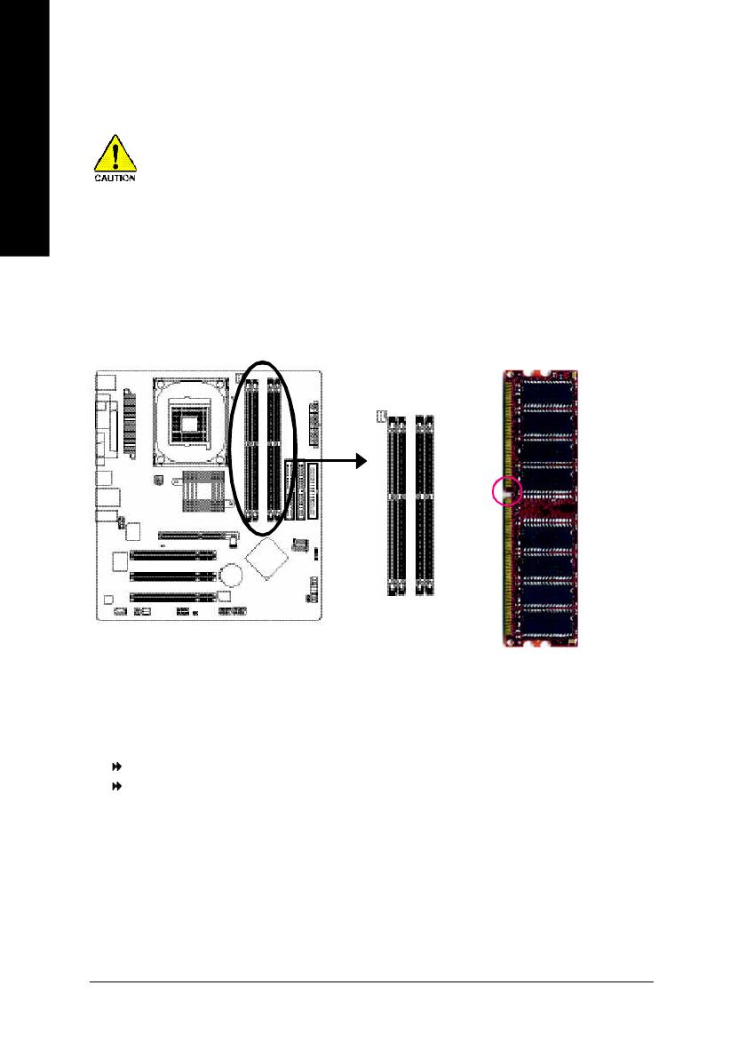
Memory — 4 184-pin DDR DIMM sockets
— Supports Dual channel DDR400/DDR333/DDR266 DIMM
— Supports 128MB/256MB/512MB/1GB unbuffered DRAM
— Supports up to 4GB DRAM (Max)
(Note 1)
— Supports only 2.5V DDR DIMM
Slots — 1 AGP slot supports 8X/4X(1.5V) mode
— 3 PCI slots support
On-Board IDE — 2 IDE bus master (UDMA33/ATA66/ATA100/ATA133) IDE ports
for up to 4 ATAPI devices
— Can connect up to 4 IDE devices
On-Board Floppy — 1 Floppy port supports 2 FDD with 360K, 720K,1.2M, 1.44M
and 2.88M bytes
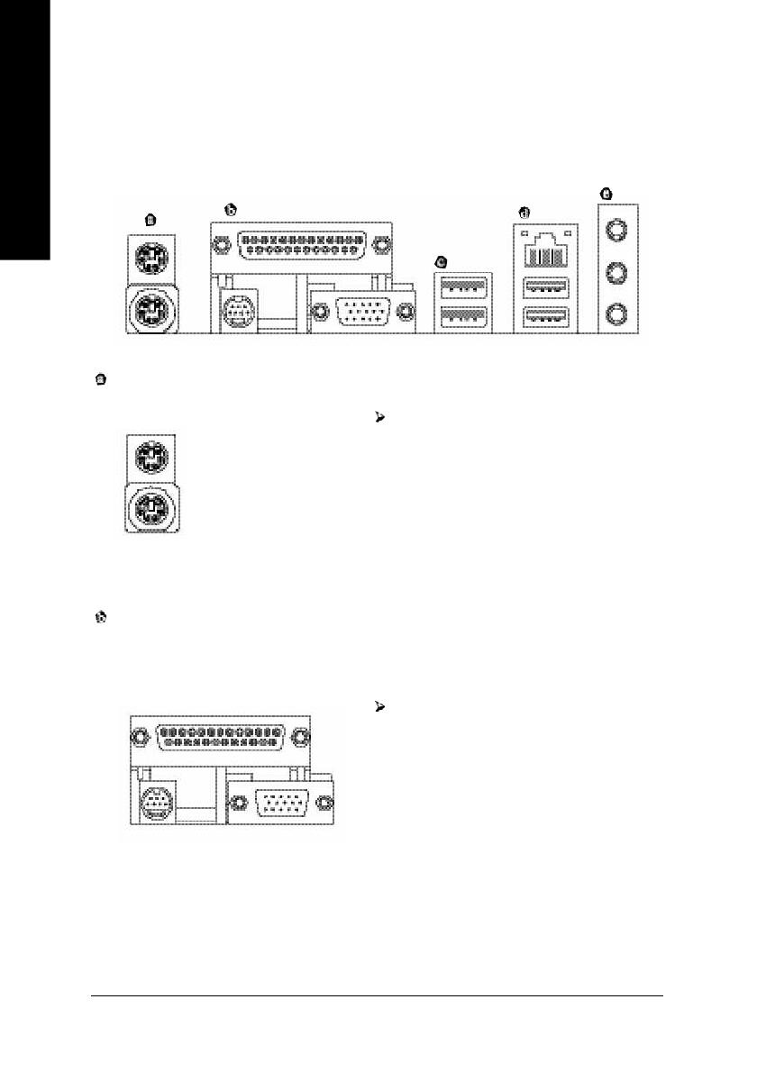
On-Board Peripherals — 1 Parallel port supports Normal/EPP/ECP mode
— 1 TV Out,1 VGA port,COMA on board
— 8 USB 2.0/1.1 ports (4 x Rear, 4 x Front by cable)
— 1 IrDA connector for IR
— 1 Front Audio connector
On-Board LAN — Build in RTL8100C Chipset (10/100 Mbit)
— 1 RJ45 port
On-Board Sound — Realtek ALC655 CODEC
— Line Out / 2 front speaker
— Line In / 2 rear speaker(by s/w switch)
— Mic In / center& subwoofer(by s/w switch)
— SPDIF Out /SPDIF In
— CD_In