Page is loading ...

i
RS350M
G52-M7031X1
MS-7031 (v1.X) M-ATX Mainboard

ii
Manual Rev: 1.0
Release Date: September 2004
FCC-B Radio Frequency Interference Statement
This equipment has been tested and found to comply with the limits for a class B
digital device, pursuant to part 15 of the FCC rules. These limits are designed to
provide reasonable protection against harmful interference when the equipment is
operated in a commercial environment. This equipment generates, uses and can
radiate radio frequency energy and, if not installed and used in accordance with the
instruction manual, may cause harmful interference to radio communications. Operation
of this equipment in a residential area is likely to cause harmful interference, in which
case the user will be required to correct the interference at his own expense.
Notice 1
The changes or modifications not expressly approved by the party responsible for
compliance could void the user’s authority to operate the equipment.
Notice 2
Shielded interface cables and A.C. power cord, if any, must be used in order to
comply with the emission limits.
VOIR LA NOTICE D’INSTALLATION AVANT DE RACCORDER AU RESEAU.
Micro-Star International
MS-7031
This device complies with Part 15 of the FCC Rules. Operation is subject to the
following two conditions:
(1) this device may not cause harmful interference, and
(2) this device must accept any interference received, including interference that
may cause undesired operation

iii
Copyright Notice
The material in this document is the intellectual property of MICRO-STAR
INTERNATIONAL. We take every care in the preparation of this document, but no
guarantee is given as to the correctness of its contents. Our products are under
continual improvement and we reserve the right to make changes without notice.
Trademarks
All trademarks are the properties of their respective owners.
AMD, Athlon™, Athlon™ XP, Thoroughbred™, and Duron™ are registered
trademarks of AMD Corporation.
Intel
®
and Pentium
®
are registered trademarks of Intel Corporation.
PS/2 and OS
®
/2 are registered trademarks of International Business Machines
Corporation.
Microsoft is a registered trademark of Microsoft Corporation. Windows
®
98/2000/NT/
XP are registered trademarks of Microsoft Corporation.
NVIDIA, the NVIDIA logo, DualNet, and nForce are registered trademarks or trade-
marks of NVIDIA Corporation in the United States and/or other countries.
Netware
®
is a registered trademark of Novell, Inc.
Award
®
is a registered trademark of Phoenix Technologies Ltd.
AMI
®
is a registered trademark of American Megatrends Inc.
Kensington and MicroSaver are registered trademarks of the Kensington Technology
Group.
PCMCIA and CardBus are registered trademarks of the Personal Computer Memory
Card International Association.
Revision History
Revision Revision History Date
V1.0 First release of PCB 1.0 with September 2004
ATi RAdeon 9100 IGP Pro & ATi IXP 300

iv
1. Always read the safety instructions carefully.
2. Keep this User’s Manual for future reference.
3. Keep this equipment away from humidity.
4. Lay this equipment on a reliable flat surface before setting it up.
5. The openings on the enclosure are for air convection hence protects the equip-
ment from overheating. Do not cover the openings.
6. Make sure the voltage of the power source and adjust properly 110/220V be-
fore connecting the equipment to the power inlet.
7. Place the power cord such a way that people can not step on it. Do not place
anything over the power cord.
8. Always Unplug the Power Cord before inserting any add-on card or module.
9. All cautions and warnings on the equipment should be noted.
10. Never pour any liquid into the opening that could damage or cause electrical
shock.
11. If any of the following situations arises, get the equipment checked by a service
personnel:
h The power cord or plug is damaged.
h Liquid has penetrated into the equipment.
h The equipment has been exposed to moisture.
h The equipment has not work well or you can not get it work according to
User’s Manual.
h The equipment has dropped and damaged.
h The equipment has obvious sign of breakage.
12. Do not leave this equipment in an environment unconditioned, storage
temperature above 60
0
C (140
0
F), it may damage the equipment.
Safety Instructions
CAUTION: Danger of explosion if battery is incorrectly replaced.
Replace only with the same or equivalent type recommended by the
manufacturer.
Technical Support
If a problem arises with your system and no solution can be obtained from the user’s
manual, please contact your place of purchase or local distributor. Alternatively,
please try the following help resources for further guidance.
h Visit the MSI homepage & FAQ site for technical guide, BIOS updates, driver
updates, and other information: http://www.msi.com.tw & http://www.msi.
com.tw/program/service/faq/faq/esc_faq_list.php
h Contact our technical staff at: [email protected]

v
CONTENTS
FCC-B Radio Frequency Interference Statement ........................................................ ii
Copyright Notice ........................................................................................................... iii
Revision History............................................................................................................ iii
Safety Instructions ...................................................................................................... iv
Technical Support ........................................................................................................ iv
Chapter 1. Getting Started................................................................................... 1-1
Mainboard Specifications ....................................................................................1-2
Mainboard Layout ................................................................................................ 1-4
MSI Special Features ...........................................................................................1-5
Chapter 2. Hardware Setup ................................................................................. 2-1
Quick Components Guide ....................................................................................2-2
Central Processing Unit: CPU............................................................................... 2-3
Example of CPU Core Speed Derivation Procedure ..................................... 2-3
Memory Speed/CPU FSB Support Matrix..................................................... 2-3
CPU Installation Procedures for Socket 478 ............................................... 2-4
Installing the CPU Fan ................................................................................... 2-5
Memory................................................................................................................. 2-6
Introduction to DDR SDRAM ......................................................................... 2-6
DDR Population Rules.................................................................................... 2-7
Installing DDR Modules.................................................................................. 2-7
Power Supply ......................................................................................................2-8
ATX 20-Pin Power Connector: ATX1 ........................................................... 2-8
ATX 12V Power Connector: JPW1 ..............................................................2-8
Back Panel............................................................................................................2-9
Mouse Connector .........................................................................................2-9
Keyboard Connector .................................................................................... 2-9
RJ-45 LAN Jack: 10/100 LAN (8100C) /
Giga-bit LAN (8110SB) (Optional).............................................2-10
IEEE1394 Port (Optional)............................................................................. 2-11
VGA Connector (Optional) ......................................................................... 2-11
Serial Port Connector: COM1 ..................................................................... 2-11
USB Connectors..........................................................................................2-12
Audio Port Connectors ...............................................................................2-12
Parallel Port Connector: LPT1.....................................................................2-13
Connectors ........................................................................................................2-14
Floppy Disk Drive Connector: FDD1...........................................................2-14

vi
Fan Power Connectors: CPUFAN1/SYSFAN1 ..........................................2-14
Hard Disk Connectors: IDE1 & IDE2 ...........................................................2-15
CD-In Connector: JCD1 ...............................................................................2-16
SPDIF-Out Connector: JSPD1 (Optional) ...................................................2-16
Front USB Connectors: JUSB1 / JUSB2 ....................................................2-16
Front Panel Connector: JFP1......................................................................2-17
Front Panel Audio Connector: JAUD1........................................................2-17
Serial ATA Connectors controlled by ATI IXP 300: SATA1, SATA2 ..........2-18
IEEE 1394 Connector: J1394_1 (Optional).................................................2-19
TV-Out Connector: JTV1 (Optional)...........................................................2-20
Jumpers .............................................................................................................2-21
Clear CMOS Jumper: JBAT1.......................................................................2-21
Slots ...................................................................................................................2-22
AGP (Accelerated Graphics Port) Slot......................................................2-22
PCI (Peripheral Component Interconnect) Slots ........................................2-22
PCI Interrupt Request Routing ....................................................................2-22
Chapter 3. BIOS Setup........................................................................................... 3-1
Entering Setup .....................................................................................................3-2
Control Keys..................................................................................................3-2
Getting Help ................................................................................................... 3-2
The Main Menu.....................................................................................................3-3
Standard CMOS Features ...................................................................................3-5
Advanced BIOS Features ...................................................................................3-7
Advanced Chipset Features............................................................................... 3-9
Integrated Peripherals .......................................................................................3-12
Power Management Setup................................................................................3-16
PNP/PCI Configurations ..................................................................................... 3-18
PC Health Status................................................................................................3-20
Frequency/Voltage Control ...............................................................................3-21
Load Fail-Safe/Optimized Defaults...................................................................3-23
BIOS Setting Password ....................................................................................3-24
Chapter 4. Introduction to ALC655 Audio Codec........................................... 4-1
Installing the Audio Driver ...................................................................................4-2
Installation for Windows 2000/XP ................................................................4-2
Using 2-, 4-, or 6- Channel Audio Function ....................................................... 4-4
Using the Back Panel ....................................................................................4-4
Testing the Connected Speakers .......................................................................4-8

vii
Playing KaraOK..................................................................................................4-10
Chapter 5. Introduction to ATi IXP 300 SATA RAID.......................................... 5-1
Introduction .......................................................................................................... 5-2
BIOS Configuration ..............................................................................................5-3
Installing Software ..............................................................................................5-5

1-1
Getting Started
Thank you for purchasing RS350M Series (MS-7031) v1.X
Micro ATX mainboard. The RS350M Series is based on ATI
®
Radeon
9100 IGP Pro & ATI
®
IXP 300 chipsets and provides 8 USB 2.0
ports for high-speed data transmission. With all these special
designs, the RS350M Series delivers a high performance and pro-
fessional desktop platform solution.
Getting Started

1-2
MS-7031 Micro ATX Mainboard
Mainboard Specifications
CPU
h Socket 478 for P4 processors (Northwood/Prescott) at 400/533/800 MHz
h Supports up to 3.4GHz.
h Hyper-Threading CPU.
(For the latest information about CPU, please visit http://www.msi.com.tw/program/
products/mainboard/mbd/pro_mbd_cpu_support.php)
Chipset
h ATI Radeon 9100 IGP Pro
- Supports AGP 8x/4x at 0.8V (AGP 3.0) or 4x at 1.5V
- Supports TV-out (optional)
- Supports ATI Surround View
- ATI RADEON 9200 graphic controller Integrated
- Supports 266/333/400MHz memory FSB
h ATI IXP 300
- AC’97 2.2 interface
- 8 USB 2.0/1.1 ports
- 2 channel Ultra ATA33/66/100/133 Bus Master IDE controller
- Supports RAID 0, 1 & 2 SATA ports
Main Memory
h Supports four 184-pin unbuffered DDR 266/333/400 DIMMs.
h Supports up to 4GB memory size without ECC.
(For the updated supporting memory modules, please visit http://www.msi.com.tw/
program/products/mainboard/mbd/pro_mbd_trp_list.php.)
Slots
h One AGP (Accelerated Graphics Port) slot that supports AGP 3.0 8x/4x.
h Three PCI 2.2 32-bit Master PCI Bus slots (support 3.3V/5V PCI bus interface).
On-Board IDE
h One Ultra DMA 33/66/100/133 IDE controllers integrated in ATI IXP 300.
- Supports PIO, Bus Master operation modes.
- Can connect up to four Ultra ATA drives.
- Support Bus Master, Ultra DMA 33/66/100/133 operation modes
h Serial ATA 150 controller integrated in ATI IXP 300.
- Up to 150MB/sec transfer speed.
- Can connect up to two Serial ATA devices.
- Supports SATA Raid 0 and Raid 1 function.
On-Board Peripherals
h On-Board Peripherals include:
- 1 floppy port supports 1 FDD with 360K, 720K, 1.2M, 1.44M and 2.88 Mbytes.
- 1 serial port (COM1) and 1 VGA port
- 1 parallel port supports SPP/EPP/ECP mode
- 8 USB 2.0/1.1 ports (Rear * 4 / Front * 4)

1-3
Getting Started
- 1 Line-In/Line-Out/Mic-In port
- 1 RJ-45 LAN connector
- 1 IEEE 1394 port (Optional)
- 1 CD-IN pin header
IEEE1394 (Optional)
h VIA VT6307 PCI Controller with integrated PHY (optional)
h Supports 2 1394 ports (Rear x1 / Front x 1)
Audio
h AC97 link controller integrated in ATI IXP 300.
h 6 channels S/W audio codec Realtek ALC655 codec
- Compliance with AC97 2.2 Spec
- Meets PC2001 audio performance requirement
h Supports SPDIF-Out pin header (Optional)
LAN (Optional)
h Realtek RTL8100C/8110SB
- Support 10Mb/s, 100Mb/s and 1000Mb/s (1000Mb/s only for 8110SB auto-nego-
tiation operation.
- Compliance with PCI 2.2 standard.
h Supports Wake-On-LAN and remote wake-up.
h Supports ACPI power management.
BIOS
h 4MB Award BIOS with PNP BIOS, ACPI, SMBIOS 2.3, Green and Boot Block.
h Provides DMI 2.0, WFM 2.0, WOL, WOR, chassis intrusion, and SMBus for system
management.
Dimension
h Micro-ATX Form Factor: 24.4 cm (L) x 24.4 cm (W).
Mounting
h 8 mounting holes.
Others
h Live BIOS/Live Driver Update
h PC2001 Compliant
h Suspends to RAM/Disk
MSI Reminds You...
The Windows 98 & Windows ME operating systems are not sup-
ported by this mainboard.

1-4
MS-7031 Micro ATX Mainboard
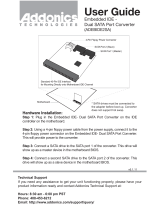
Mainboard Layout
RS350M Series (MS-7031) v1.X
Micro ATX Mainboard
D
I
M
M
2
D
I
M
M
4
D
I
M
M
1
D
I
M
M
3
AGP Slot
T: mouse
B: keyboard
T:
Line-Out
B:Mic
Line-In
M:
JAUD1
JTV1
(Optional)
JSPD1
(Optional)
JCD1
C
o
d
e
c
V
I
A
V
t
6
3
0
7
(
O
p
t
i
o
n
a
l
)
R
T
L
8
1
0
0
C
B
A
T
T
+
BIOS
Winbond
W83627THF
ATI
IXP300
ATI
Radeon
9100 IGP Pro
I
D
E
1
I
D
E
2
F
D
D
1
PCI Slot 1
PCI Slot 2
PCI Slot 3
SYSFAN1
CPUFAN1
JFP1
JPW1
A
T
X
P
o
w
e
r
S
u
p
p
l
y
JCMOS1
JUSB1
SATA2
SATA1
JUSB2
J1394_1
(Optional)

1-5
Getting Started
MSI Special Features
Live Update
The Live Update 3™ is a tool used to detect and update your BIOS/
drivers/VGA BIOS/VGA Driver/OSD/Utility online so that you don’t
need to search for the correct BIOS/driver version throughout the
whole Web site. To use the function, you need to install the “MSI Live
Update 3” application. After the installation, the “MSI Live Update 3”
icon (as shown on the right) will appear on the screen.
Double click the “MSI Live Update 3” icon, and the following screen
will appear:
Six buttons are placed on the left column of the screen. Click the desired button to
start the update process.
Live BIOS – Updates the BIOS online.
Live Driver – Updates the drivers online.
Live VGA BIOS – Updates the VGA BIOS online.
Live VGA Driver – Updates the VGA driver online.
Live OSD – Updates the firmware of the OSD products online.
Live Utility – Updates the utilities online.
If the product you purchased does not support any of the functions listed above, a
“sorry” message is displayed. For more information on the update instructions, insert
the companion CD and refer to the “Live Update Guide” under the “Manual” Tab.

1-6
MS-7031 Micro ATX Mainboard
Core Center
CoreCenter is just like your PC doctor that can detect, view and adjust the PC
hardware and system status during real time operation.
In the left side it shows the current system status including the Vcore, 3.3V, +5V and
12V. In the right side it shows the current PC hardware status such as the CPU &
system temperatures and all fans speeds.
When you click the red triangles in the left and right sides, two sub-menus will open
for users to adjust the thresholds of system to send out the warning messages.

1-7
Getting Started
Left-wing: Current system status
In the left sub-menu, you can configure the settings of FSB, Vcore, Memory Voltage
and AGP Voltage by clicking the radio button next to each item and make it available
(the radio button will be lighted as yellow when selected), use the “+” and “-” buttons
to adjust, then click “OK” to apply the changes. Then you can click “Save” to save
the values you just configured.
Also you may click “Auto” to start testing the maximum CPU overclocking value. The
CPU FSB will automatically increase the testing value until the PC reboots. Or you may
click “Default” to restore the default values.
Right-wing: PC hardware status during real time operation
In the right sub-menu, you can configure the PC hardware status such as CPU &
system temperatures and fan speeds. You may use the scroll bars to adjust each
item, then click “OK” to apply the changes. The values you set for the temperatures
are the maximum thresholds for the system warnings, and the value for fan speeds
are the minimum thresholds.

2-1
Hardware Setup
Chapter 2. Hardware Setup
This chapter tells you how to install the CPU, memory modules, and
expansion cards, as well as how to setup the jumpers on the mainboard.
Also, it provides the instructions on connecting the peripheral devices,
such as the mouse, keyboard, etc.
While doing the installation, be careful in holding the components
and follow the installation procedures.
Hardware Setup

2-2
MS-7031 Micro ATX Mainboard
B
A
T
T
+
Quick Components Guide
JAUD1, p.2-17
JTV1, p.2-20
CPU, p.2-3
Back Panel
I/O, p.2-9
CPU_FAN1, p.2-14
FDD1, p.2-14
SATA1, SATA2
p.2-18
JCD1,p.2-16
JFP1, p.2-17
SYSFAN1, p.2-14
DDR DIMMs, p.2-6
IDE2, p.2-15
JSPD1, p.2-16
AGP slot,
p.2-22
JUSB1~2,
p.2-16
J1394_1, p.2-19
PCI slots,
p.2-22
IDE1, p.2-15
JCMOS1, p.2-21
JPW1, p.2-8
ATX1, p.2-8

2-3
Hardware Setup
Central Processing Unit: CPU
Example of CPU Core Speed Derivation Procedure
If CPU Clock = 133MHz
Core/Bus ratio = 23
then CPU core speed = Host Clock x Core/Bus ratio
= 133MHz x 23
= 3.06 GHz
The mainboard supports Intel
®
Pentium
®
4/Celeron Northwood/Prescott proc-
essor in the 478 pin package. The mainboard uses a CPU socket called PGA478 for
easy CPU installation. When you are installing the CPU, make sure the CPU has a
heat sink and a cooling fan attached on the top to prevent overheating. If
you do not find the heat sink and cooling fan, contact your dealer to purchase and
install them before turning on the computer.
For the latest information about CPU, please visit http://www.msi.com.tw/
program/products/mainboard/mbd/pro_mbd_cpu_support.php
Memory Speed/CPU FSB Support Matrix
MSI Reminds You...
For the tested & compatible memory modules, please go to MSI
global website (http://www.msi.com.tw) for the updated details.
FSB
Memory
DDR 266
400 MHz
DDR 333
533 MHz
800 MHz
OK OK
OK
OK
DDR 400
OK
OK
OK
OK
OK
MSI Reminds You...
Overheating
Overheating will seriously damage the CPU and system, always make
sure the cooling fan can work properly to protect the CPU from
overheating. If the system shuts down automatically, please unplug
the power cord and check the cooling fan.
Replacing the CPU
While replacing the CPU, always turn off the ATX power supply or
unplug the power supply’s power cord from grounded outlet first to
ensure the safety of CPU.

2-4
MS-7031 Micro ATX Mainboard
1. Please turn off the power and
unplug the power cord before
installing the CPU.
2. Pull the lever sideways away
from the socket. Make sure to
raise the lever up to a 90-de-
gree angle.
3. Look for the cut edge. The cut
edge should point towards the
lever pivot. The CPU can only fit
in the correct orientation.
4. If the CPU is correctly installed,
the pins should be completely
embedded into the socket and
can not be seen. Please note
that any violation of the correct
installation procedures may
cause permanent damages to
your mainboard.
5. Press the CPU down firmly into
the socket and close the lever.
As the CPU is likely to move while
the lever is being closed, al-
ways close the lever with your
fingers pressing tightly on top of
the CPU to make sure the CPU is
properly and completely embed-
ded into the socket.
CPU Installation Procedures for Socket 478
Open Lever
Sliding
Plate
Dot / Cut edge
Close
Lever
Press down
the CPU
90 degree
Dot / Cut edge
Correct CPU placement
Dot / Cut edge
Incorrect CPU placement
X
O

2-5
Hardware Setup
5. Connect the fan power cable from
the mounted fan to the 3-pin fan
power connector on the board.
Installing the CPU Fan
As processor technology pushes to faster speeds and higher performance,
thermal management becomes increasingly important. To dissipate heat, you need to
attach the CPU cooling fan and heatsink on top of the CPU. Follow the instructions
below to install the Heatsink/Fan:
2. Position the heatsink onto the reten-
tion mechanism.
1. Locate the CPU and its retention
mechanism on the motherboard.
3. Mount the fan on top of the heatsink.
Press down the fan until its four clips
get wedged in the holes of the re-
tention mechanism.
4. Press the two levers down to fasten
the fan. Each lever can be pressed
down in only ONE direction.
retention mechanism
levers
MSI Reminds You...
If your Intel Pentium 4 proces-
sor supports 3.0GHz (and
up), please be sure to use a
multi-direction fan to make the heatsink
exhausts air towards the voltage regu-
lators on the board easier. Multi-direc-
tion fan has better performance in CPU
overheating.
fan power cable

2-6
MS-7031 Micro ATX Mainboard
Memory
DDR DIMM Slots
(DIMM 1~4, from left to right)
Channel A: DIMM1 & DIMM2 (green)
Channel B: DIMM3 & DIMM4 (purple)
The mainboard provides 4 slots for 184-pin, 2.5V DDR DIMM with 8 memory
banks. You can install DDR266 / DDR333 / DDR400 SDRAM modules on the DDR DIMM
slots (DIMM 1~4). To operate properly, at least one DIMM module must be installed.
Introduction to DDR SDRAM
DDR (Double Data Rate) SDRAM is similar to conventional SDRAM, but doubles
the rate by transferring data twice per cycle. It uses 2.5 volts as opposed to 3.3 volts
used in SDR SDRAM, and requires 184-pin DIMM modules rather than 168-pin DIMM
modules used by SDR SDRAM. Please note that the DDR SDRAM does not support
ECC (error correcting code) and registered DIMM.
DDR Population Rules
Install at least one DIMM module on the slots. Each DIMM slot supports up to a
maximum size of 1GB. Users can install either single- or double-sided modules to
meet their own needs. Please note that each DIMM can work respectively for
single-channel DDR, but there are some rules while using dual-channel
DDR (Please refer to the suggested DDR population table on p.2-7). Users may install
memory modules of different type and density on different-channel DDR DIMMs.
However, the same type and density memory modules are necessary while
using dual-channel DDR, or instability may happen.
MSI Reminds You...
For the tested & compatible memory modules, please go to MSI
global website (http://www.msi.com.tw) for the updated details.
/